With a laser, so-called Cycloids or Lissajous figures can be projected via two rotating or oscillating mirrors. Before I designed a fully electronic control for the different rotational speeds of the motors, I thought it would be instructive to first see how the rotational speed ratios could be controlled completely mechanically.
The final prototype of a gearbox with six ascending whole gears runs remarkably smoothly. However, some custom parts had to be 3D printed.
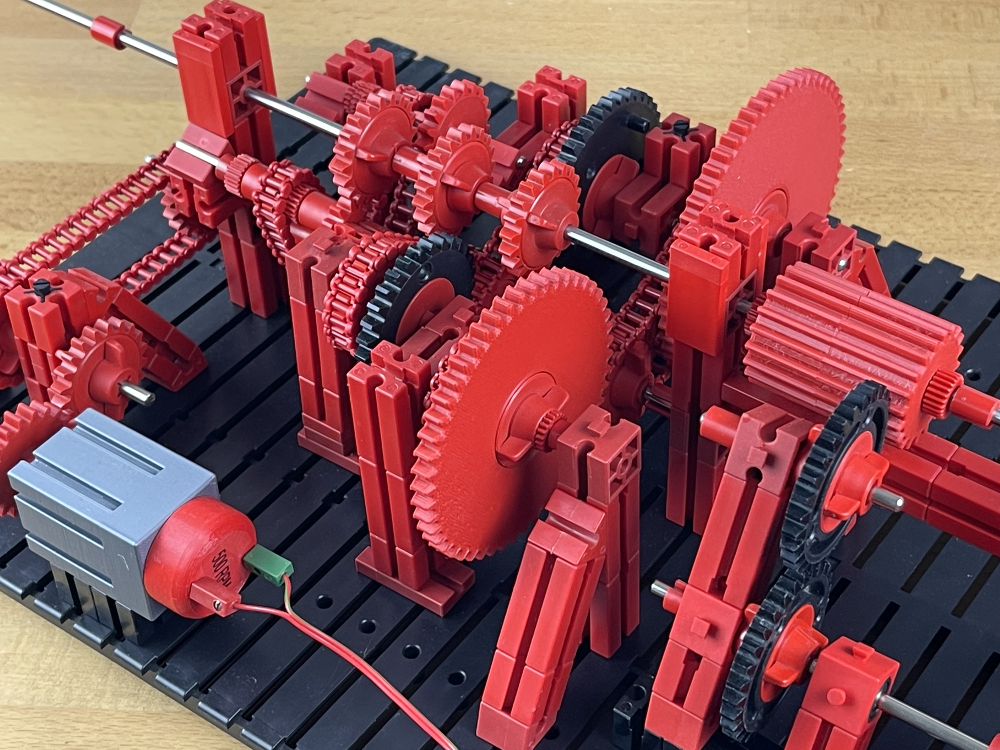
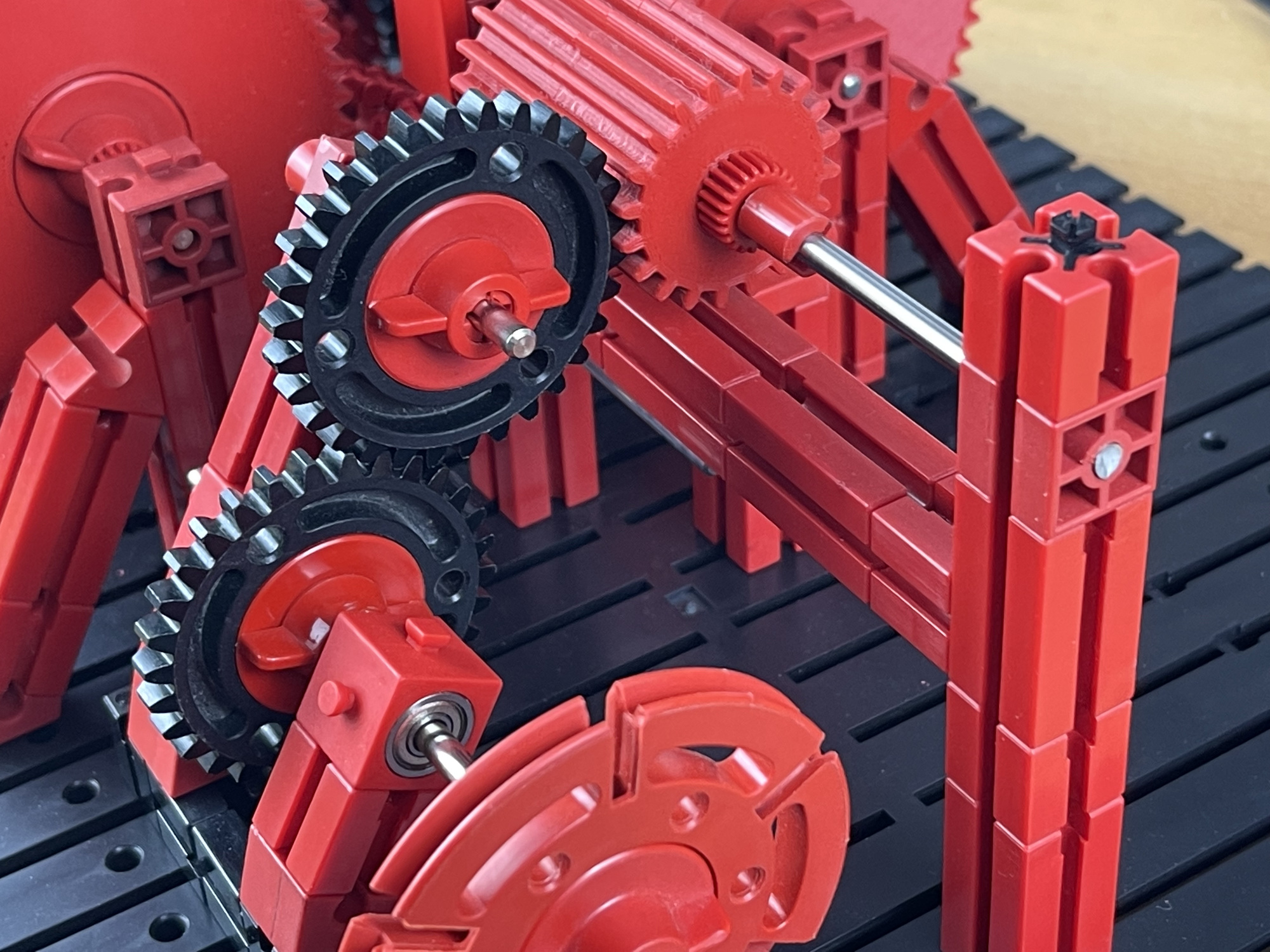
The principle of a traditional mechanical gearbox is simple in itself. A central sliding shaft with a few gears can be moved past gears with the same rotational speed but different number of teeth to select the various 'gear-ratios'.
The central motor shaft is located at the bottom and transfers the drive with chains to six wheels with an increasing number of teeth. There are gears with 10, 20, 30, 40, 50 and 60 teeth along which the sliding gear shaft can move.
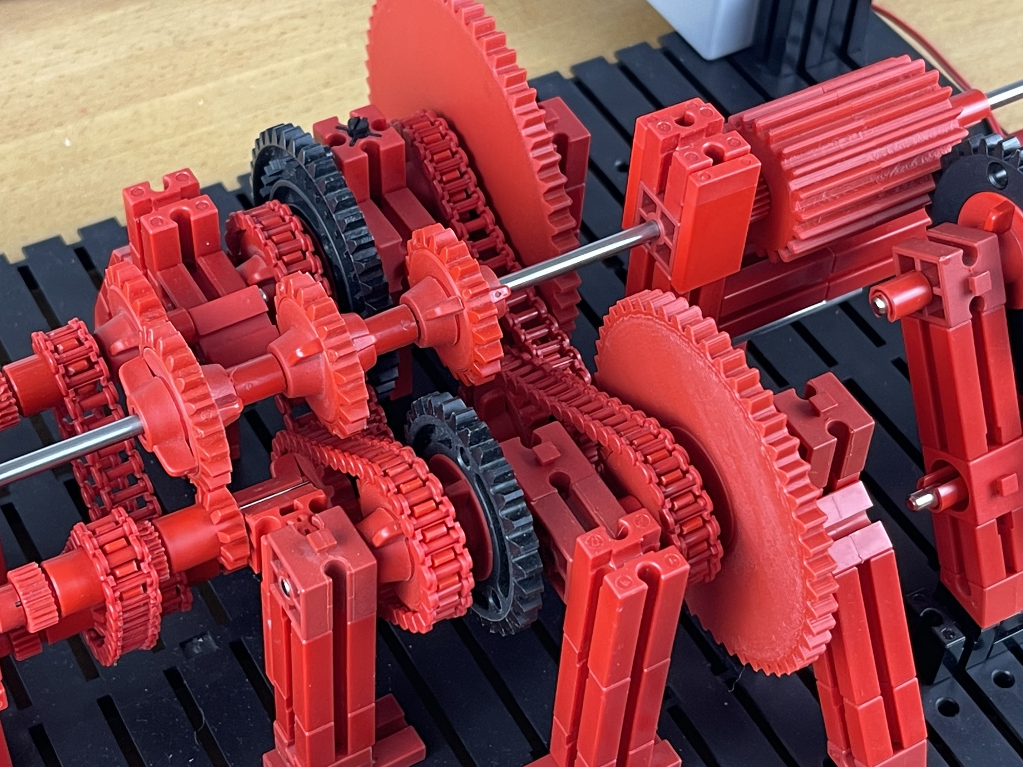
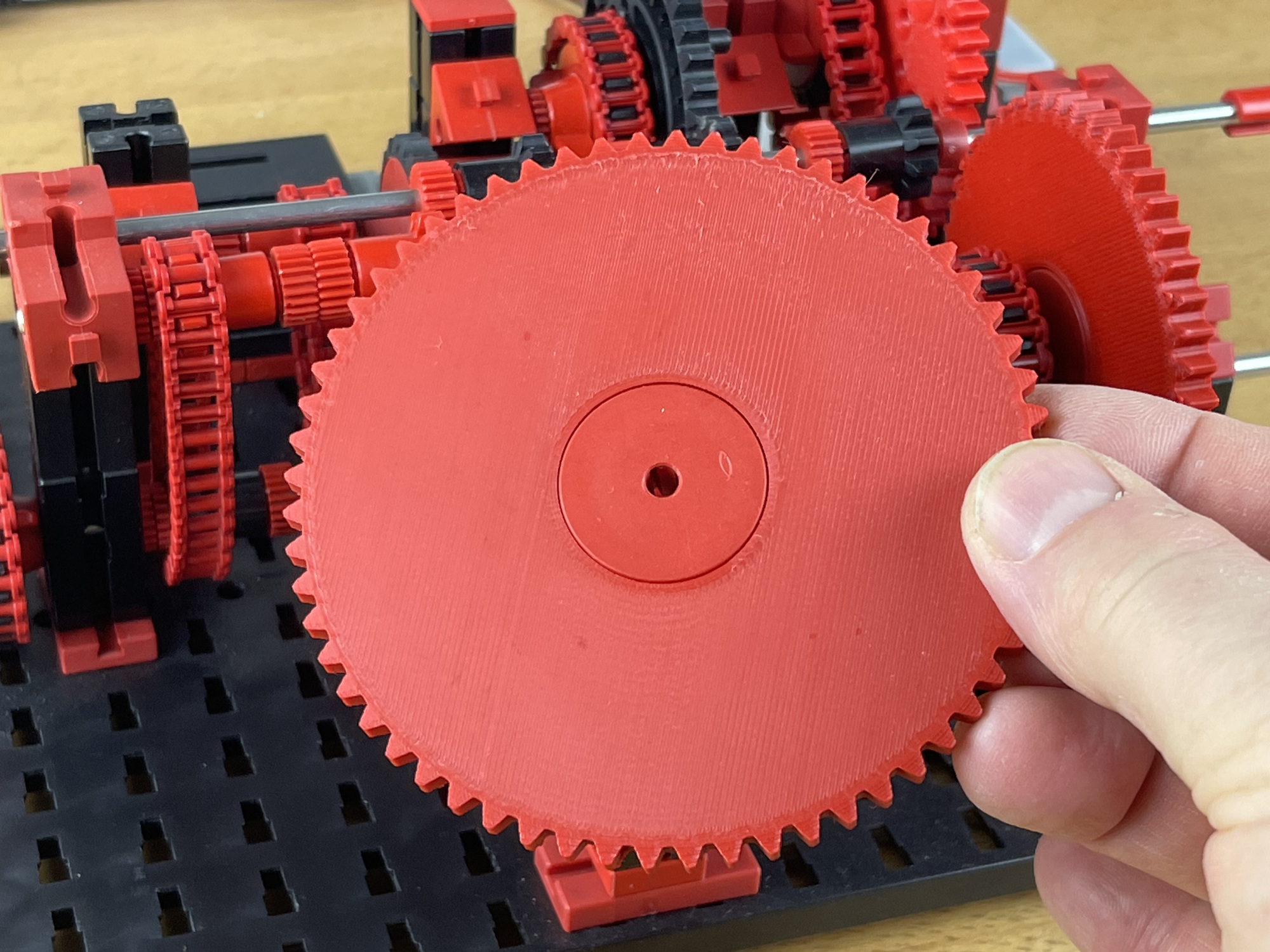
However, the gears with 50 and 60 teeth, as well as a solution to reduce the rotational movement of the gear shaft, did not yet exist with the construction material used. The 3D printer offered a solution here. The sliding 'gear-barrel' transmits the ultimately selected rotational speed to the output shaft.
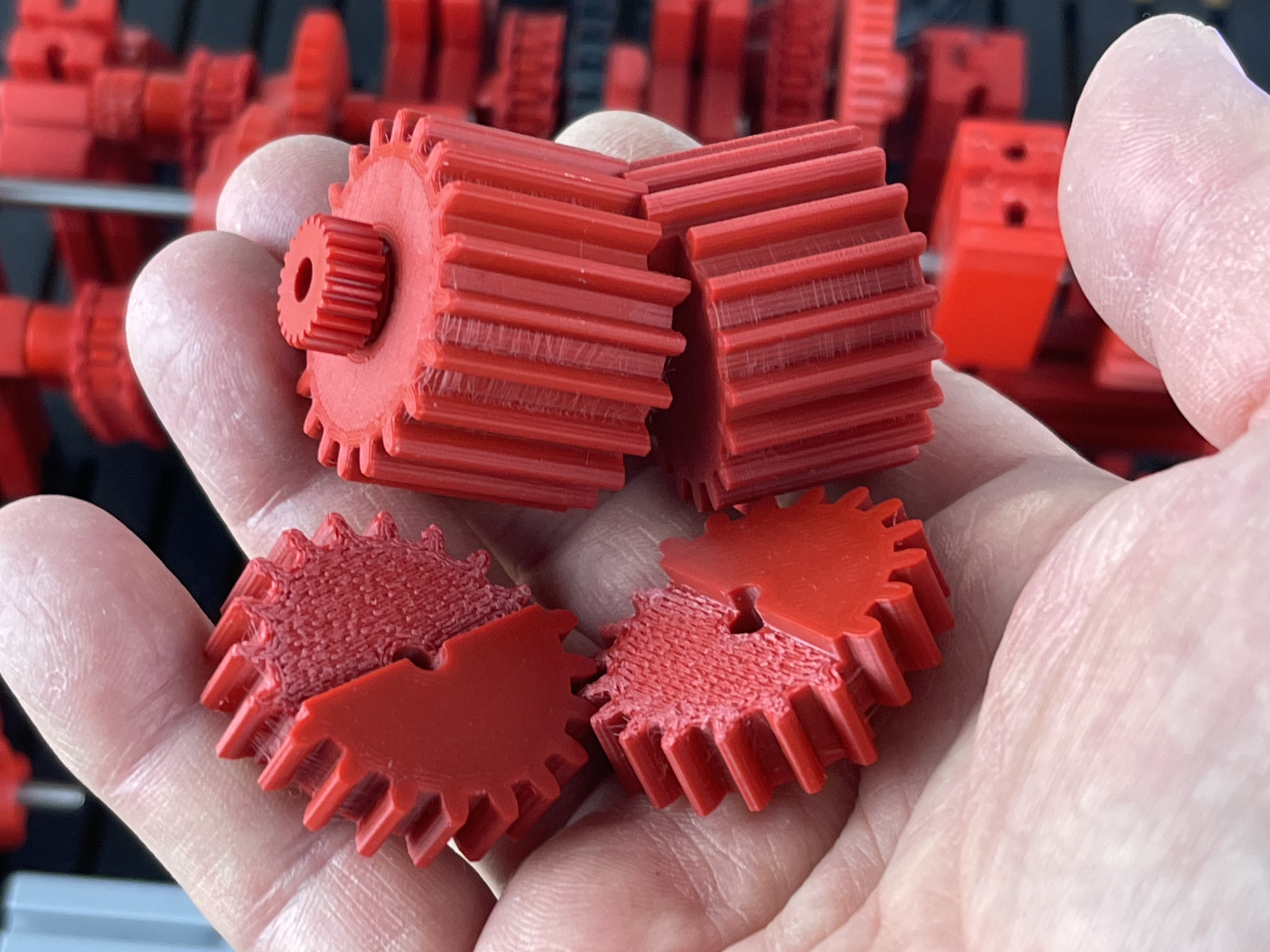
On a first model I had equipped the sliding shaft with three rather small cogs with only 10 teeth. With the construction material used (fischertechnik), the gears have a so-called modulo 1.5 toothing. It would lead too far to discuss the technical details here, but this means that for gears with a very small diameter (less than about 17 teeth), the individual teeth can no longer exactly follow the ideal dimensions. Because they actually have too small a diameter, they should be further 'undercut' so that they no longer 'comb' optimally with other (usually larger) gears.
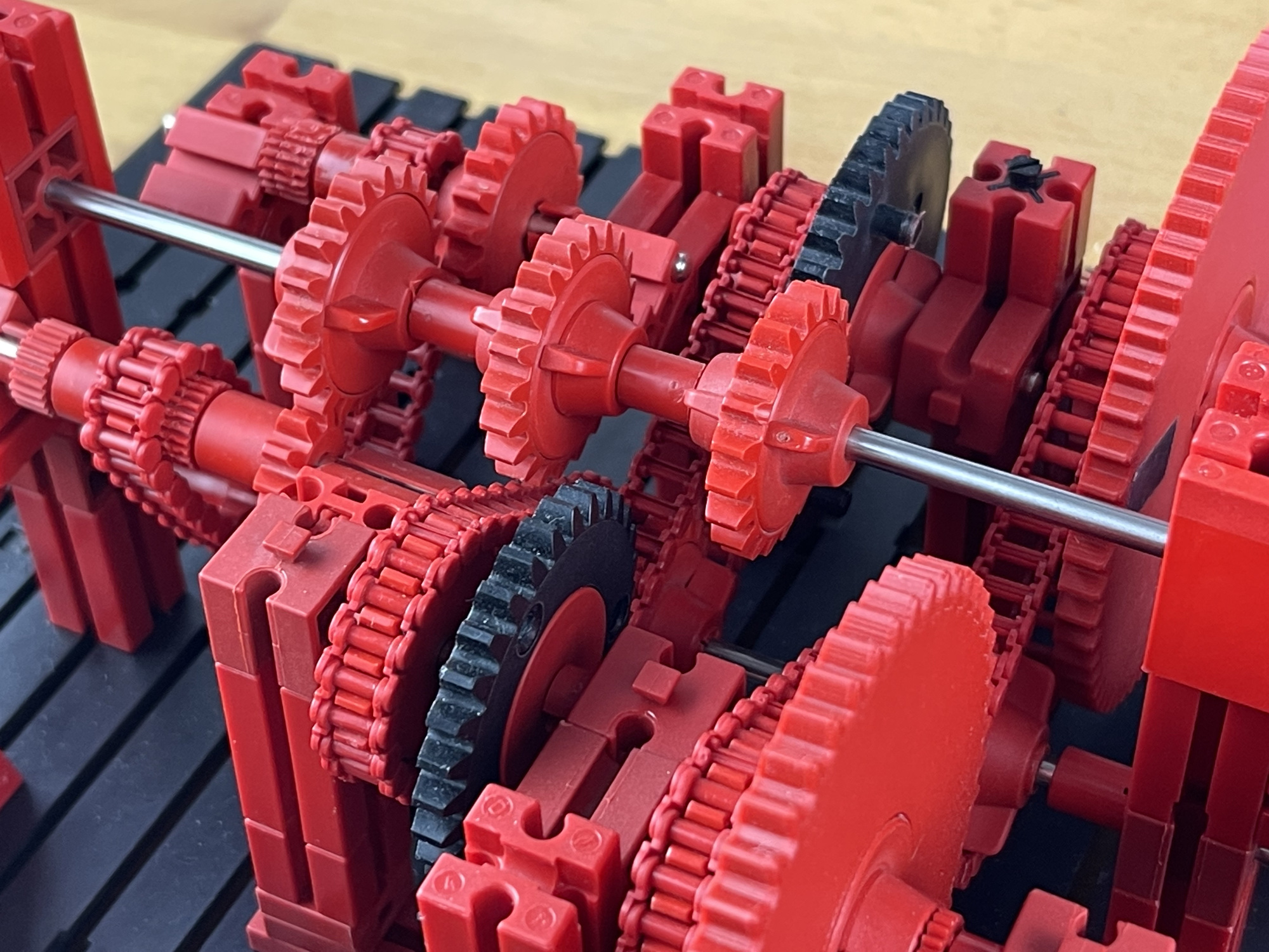
The technical construction of the gearbox should preferably be kept as simple as possible. So a series of gears on the output shaft with 10, 20, 30, 40, 50 and 60 teeth respectively, was obvious. I kept the Z10 sprocket with ten teeth as the basis for the 'first gear', because otherwise all subsequent gears could not be built analogously; with only one sprocket.
By working on the output, sliding shaft with Z20 gears (20 teeth) instead of the smaller Z10 gears, the running became smoother and quieter. Only shifting the lowest gear sometimes remains tricky, but this seemed like a small toll to pay for such a clear technical principle.
With most gearboxes it is not always required that the gears are neat consecutive numbers, but for the laser-figure project this is indispensable. Only then will instantly recognisable, more or less stationary, projected figures be projected.
With one gearbox like this the ratios 1:1, 1:2, 1:3, 1:4, 1:5 and 1:6 can now be made. But not yet ratios like 2:3, 3:5 or 4:3 and such. For this a copy of the gearbox will have to be built. In short, a fairly elaborate mechanical process. But it's still nice to go this route before we tackle the electronics and microcontrollers to control the two motors. To be continued....