In a previous project I had projected so-called hypocycloids using a semiconductor laser and two rotating mirrors. These curves were determined by the circular motion along the circumference of another circle.
If we however do not rotate the mirrors, but let each vibrate in a different direction, so-called Lissajous figures are created. As a logical continuation of the earlier experiments with laser projection, I tried to create these figures purely mechanically.
The hypocycloids projected with rotating mirrors can be expressed mathematically in polar coordinates. Formulas for Lissajous curves, on the other hand, yield Cartesian (x and y) coordinates. The figures can be projected by transferring vibrations to mirrors and are also called Bowditch curves, after Nathaniel Bowditch, who already studied them in 1815. The curves were later studied in more detail by Jules-Antoine Lissajous (1822-1880). Lissajous was a professor of mathematics at the Lyceé Saint-Louis in Paris, where he studied all kinds of vibrations and waves. In 1855 he invented a simple optical device to analyze compound vibrations. He attached mirrors to the tines of two tuning forks vibrating at right angles to each other. When a beam of light was directed at one of the mirrors, it bounced back to the other mirror and from there to a screen, where it formed a two-dimensional pattern, the result of superposition of the two vibrations. This simple device - a forerunner of the modern oscilloscope - was a novelty in its time; until then, the study of sound depended entirely on the process of hearing, that is, on the human ear. Lissajous literally made it possible to 'see sound'.
Anyone looking for more mathematical background information and theory about Lissajous figures can indulge themselves online. Much has been written about it and there are also many videos on YouTube. The Wikipedia page provides a good starting point.
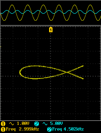
Before experimenting with mechanical oscillation and projection with a beam of light, I decided to take a look at the curves on my oscilloscope. In the XY mode of an oscilloscope, one signal determines the Y deflection and the other signal determines the X deflection, which is normally represented by the time domain. In this way, the frequency relationship of the two signals is made visible. When two sine waves were presented, recognizable Lissajous patterns soon appeared on the screen. In the adjacent image, the two sine waves presented in the time domain are visible at the top of the screen, below which the Lissajous figure with frequency ratio 2:3.
If you do not have an oscilloscope and wave generator, you can find various Lissajous simulators online with which you can experiment virtually. For example, by varying the phase shift between two waves of the same frequency, it becomes clear that the oblique line on the display is actually a side view of a tilted circle.
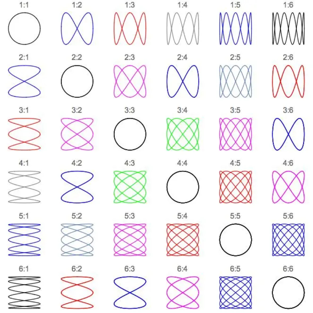
For projection with a laser beam, two mirrors must be able to be modulated independently of each other. I found the nice overview on the right online and shows some examples that (theoretically) should be able to be made with the gearbox of the previous project.
As with the hypocycloids, the final projected shape depends on the oscillation ratio of the two moving mirrors. The movement of each mirror should theoretically be in one direction as clean as possible. The challenge here is to limit the disturbing influence of movements in other directions due to vibrations and backlash in the gear transmissions as much as possible.
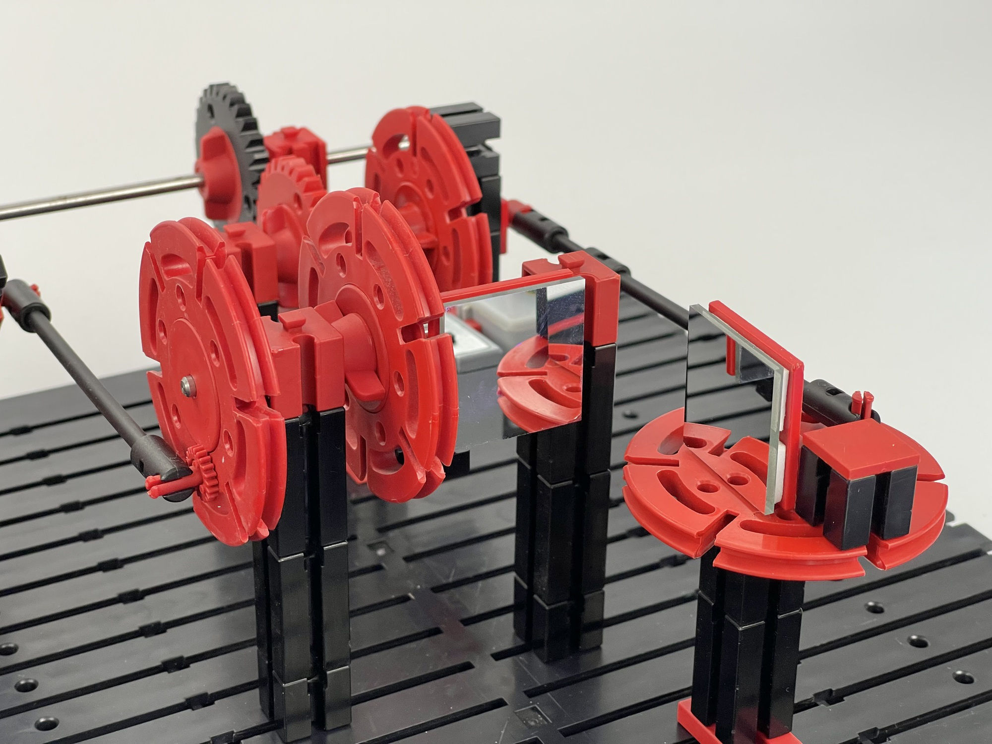
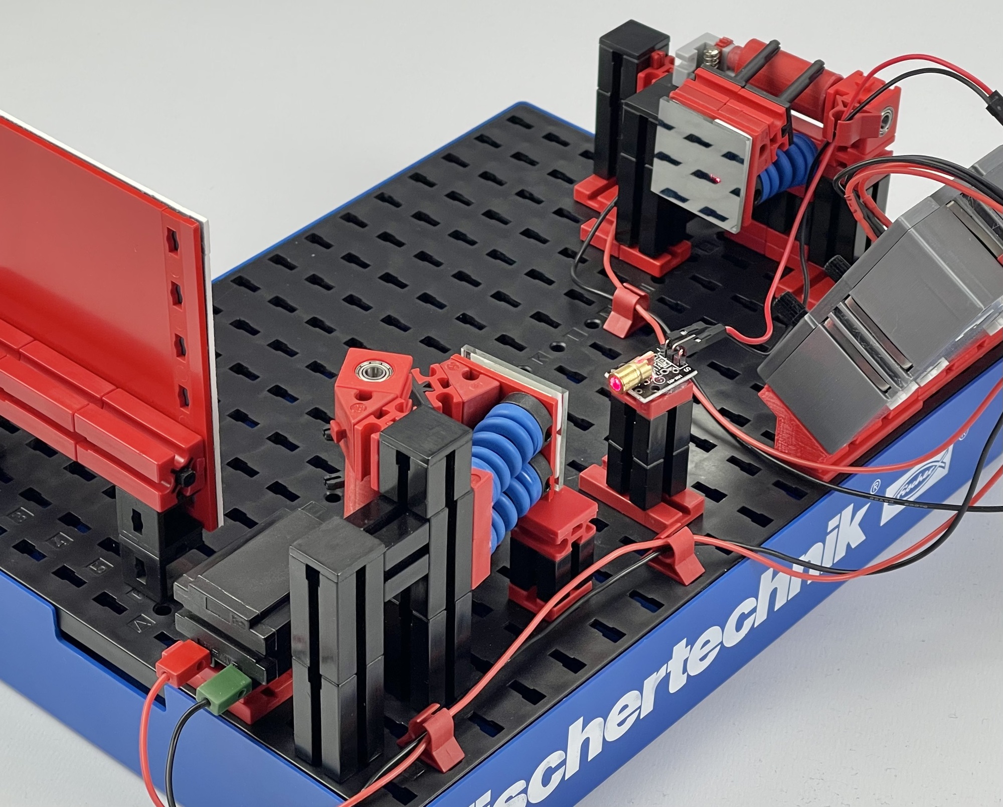
The most obvious is to make the oscillating movement with a lever. Moreover, if it is driven by an acentrically placed shaft on a rotating wheel, the movement then proceeds directly according to a pure sine wave. To this end I built the arrangement shown on the right with two oscillating mirrors on the output side of the gearbox.
The deflection of the lever should be only small. After all, the laser beam deflected by the first mirror movement must fall entirely on the second mirror. With this method, the deflection of the mirror can be adjusted by shifting the pivot point of the connecting rod. This can be set close to the axis of rotation if required.
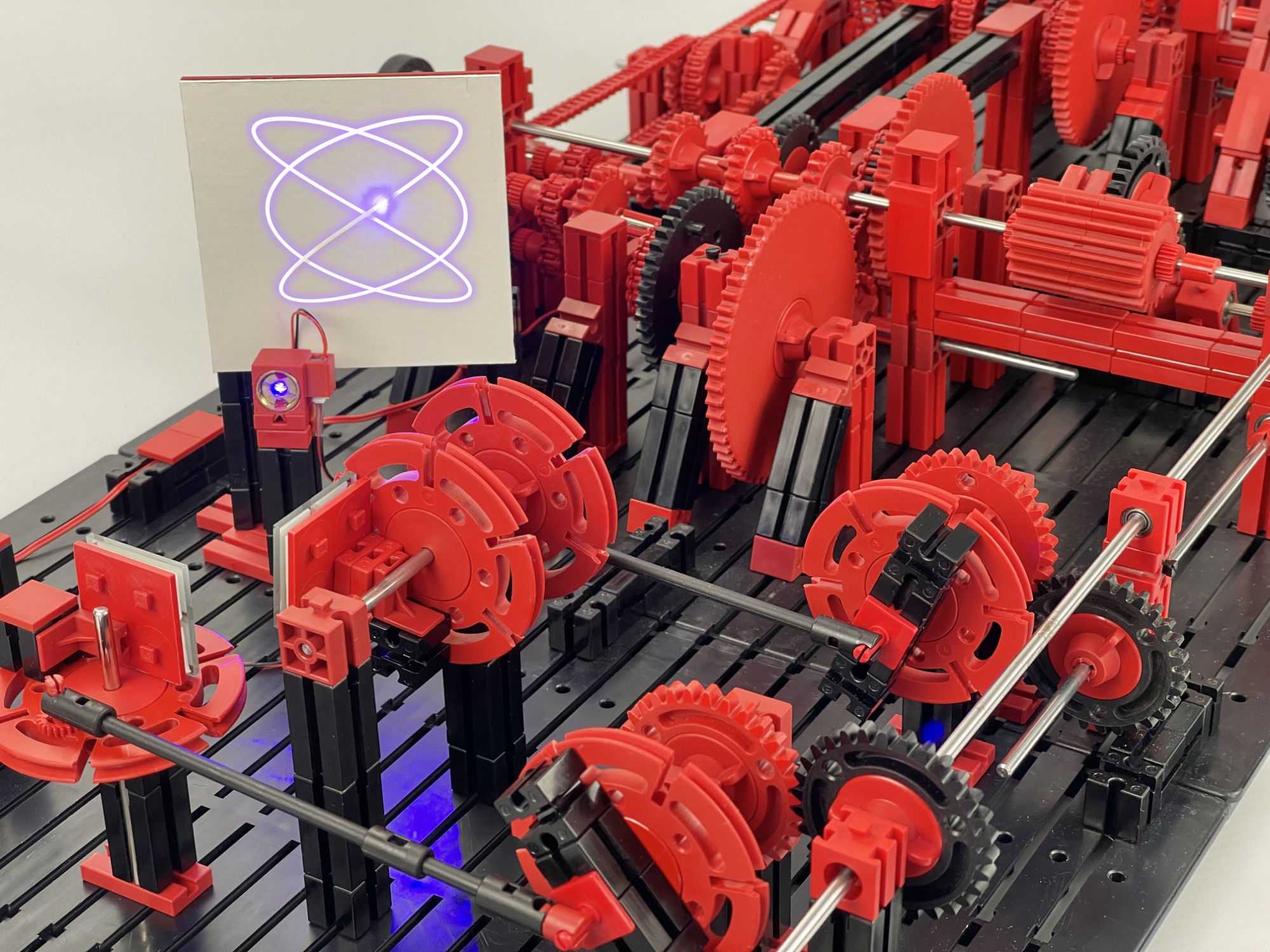
Unfortunately, the resulting projection is no more than a swift moving dot of light. The coupling of physics and optics could be demonstrated very well with it, but as expected, a maximum oscillation frequency of 25 Hz at most turned out to be too low to project well-recognizable figures. The opportunistic photomontage above hopefully gives an impression of what could not be photographed even with the slowest shutter speeds. However, on delayed movie shots that I made, it is possible to check that Lissajous curves are actually described by the point of light.
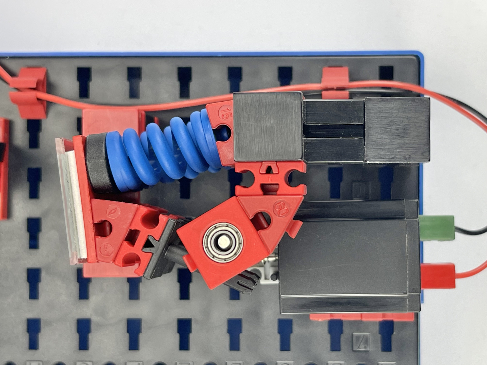
By using two separate motors, the speed of the lever method described above can of course be increased considerably. However, one complete back and forth movement of the mirror corresponds to one revolution of the drive wheel with the lever, and a short experiment showed that the forces and vibrations in the model can then increase considerably. That is why I was looking for a method in which fewer gears and masses had to be set in motion and which could also be done with fewer pivot points and levers. This is where the 3D printer came in handy again. The last prototype of an oval-shaped roller, with which the sinusoidal movement can be transferred to the mirror platform, can be seen in the adjacent photo.
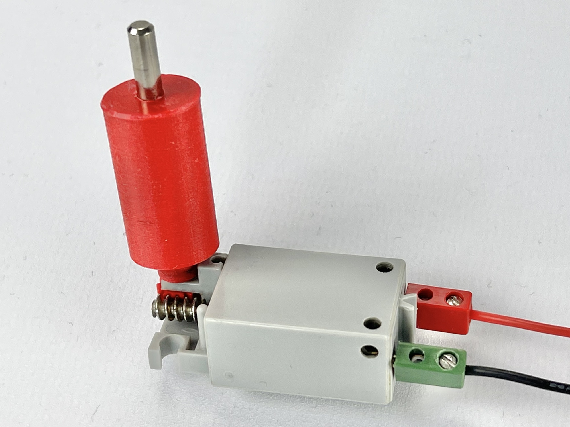
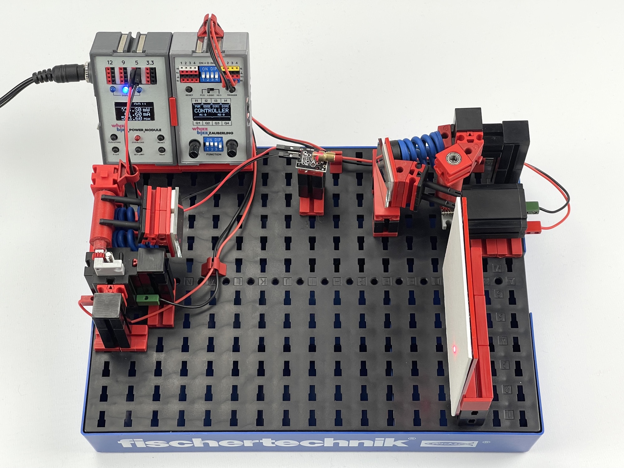
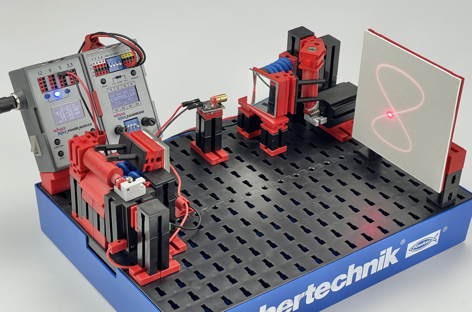
The roller can be slid directly onto the worm shaft (31069) of a fischertechnik 'Schneckengetriebe' for the Mini Motor or S-Motor (download STL file). By allowing the surface of the roller to be scanned by guides on the platform, the oscillating movement is transmitted as directly as possible with a relatively small deflection. Moreover, both platforms are driven by their own motor, so that the gearbox can be dispensed with and the whole can be accommodated on a small construction plate (after all, it saves 60 sprockets and 16 chain transmissions!). For the motor control I again chose my Zauberling, which already provides a double motor control as standard. It goes without saying that something similar can be built up with an ftDuino, fischertechnik TXT controller or even two separate motor controls.
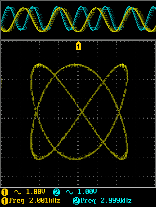
By experimenting with the different rotational speed ratios, the full range of Lissajous curves shown in Figure 2 can theoretically be traversed.
It turned out to be considerably more difficult to make the figure stand still in a really stable manner than with the two-motor hypocycloids. Due to backlash and vibrations, the deflection directions tend to pick up 'movement-noise'. The X-mirror could be supported and 'vibrates' on a table. The Y deflection vibrates freely hanging from two springs and is therefore slightly more sensitive to the disturbing influences of vibration and backlash. It is therefore certainly worth investigating whether the suspension of the mirror platforms can be improved on these points.
With some experimentation, we succeeded in projecting Lissajous figures with a semiconductor laser in a purely mechanical way. However, stable projections require fairly high speeds and and it is difficult to minimize the disturbing influences on the movement. The influence of vibrations and backlash quickly translates into a somewhat 'shivering' projection line. Moreover, the relatively low oscillation speed limits the recognisability of the figures.
Nevertheless, it can be concluded that projecting Lissajous figures with a laser is a fun and creative way to investigate the properties of waves and vibrations. There are complex and beautiful patterns to create that are both visually stunning and scientifically informative.
For professional laser projection, the mechanical solutions investigated here seem to be of little use. Specialized laser galvanometers are used for this, which make it possible to modulate the mirrors much faster and more accurately. In its simplest form, such a 'laser galvo mirror system' simply contains two small DC motors that can be moved directly with a symmetrical input signal. Perhaps it would be a possible future experiment to investigate whether the fischertechnik motors could be used for this with the right electronic control. It would eliminate the disturbing influence of mechanics, but would present us with new challenges. After all, the mirrors should be controlled with sine signals that are as pure as possible and whose frequency can be accurately controlled.