
To gain insight into the frequency behavior of a timer, monoflop or other oscillating circuit during electronics experiments, a small potentiometer fitted with soldered wires can be used in the circuit. After experimentally determining the desired value, the value of the disconnected potentiometer can then be measured. More luxurious and convenient is to use a so-called resistance decade for this purpose.
However, these are traditionally quite expensive things that I certainly do not use every day. Therefore, I was curious to see how useful the nowadays cheaply offered decade PCBs are and bought two that I provided with a nicer casing and connection options.
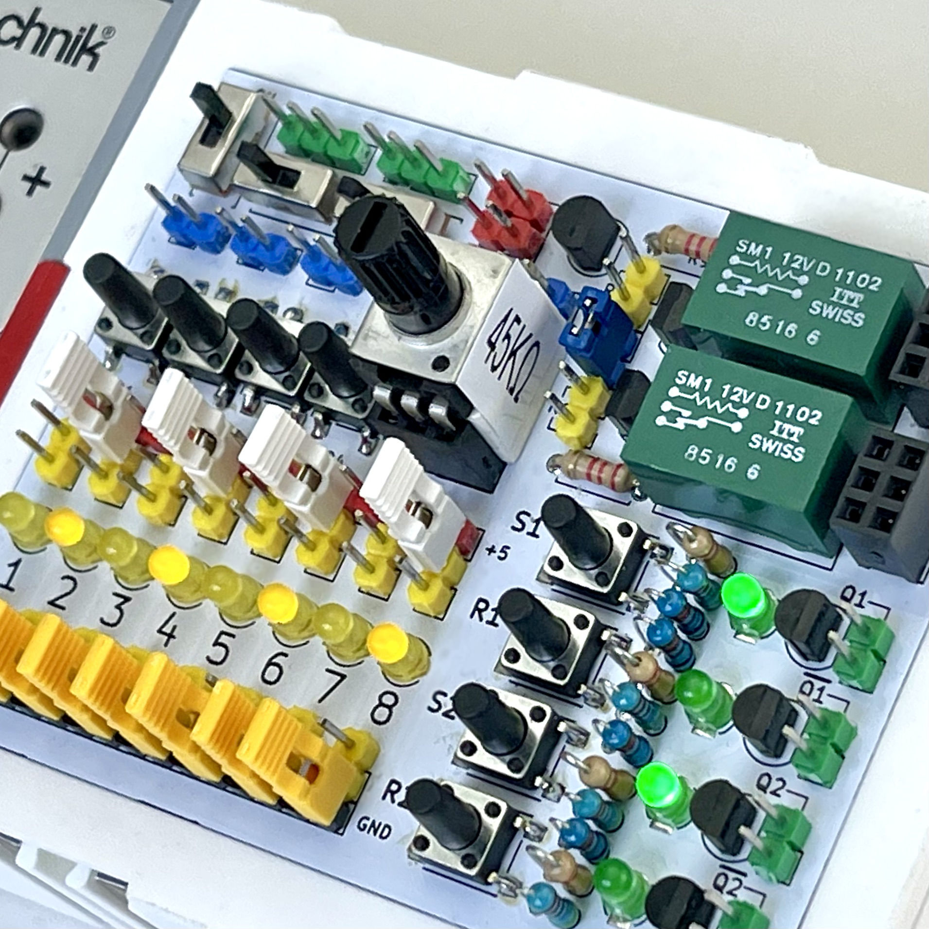
In order to already be a little more flexible with the possible values of the potentiometer, I already equipped the self-designed experiment board with modular potentiometers at the time. That way it is easier to choose a potentiometer that is in the intended experiment range.
But as with the loose potentiometers with wires, the experimentally found values will have to be measured afterwards with, for example, a multimeter. Now, with resistance values this is still a useful solution in itself, but if we want to experimentally determine the value of a capacitor in this way it becomes a bit more difficult. The adjustable range of these variable components is usually relatively small.
Anyone who has ever experimented with electronic circuits knows that for some experiments it would be even nicer to have a resistor that can be adjusted in steps and whose value can be read directly.
To easily experiment with resistor, capacitor or coil values over an even wider range, there are so-called "decade boxes". These contain a series of resistors, capacitors or coils that are incrementally adjustable to obtain a resistor, capacitor or coil with a specific value. Decade boxes are ideal for solving circuit problems and checking the accuracy of test equipment, both in the field and in the lab.
Such a decade simply contains a series of individual components that can be connected in series, or in the case of capacitors in parallel, at will. Each "decade" is formed by the same components of the same value. Each configurable sequence of units, tens, hundreds or thousands thus differs from the previous one by a factor of 10, so with, say, three decades, values from 0 to 999 can be made.
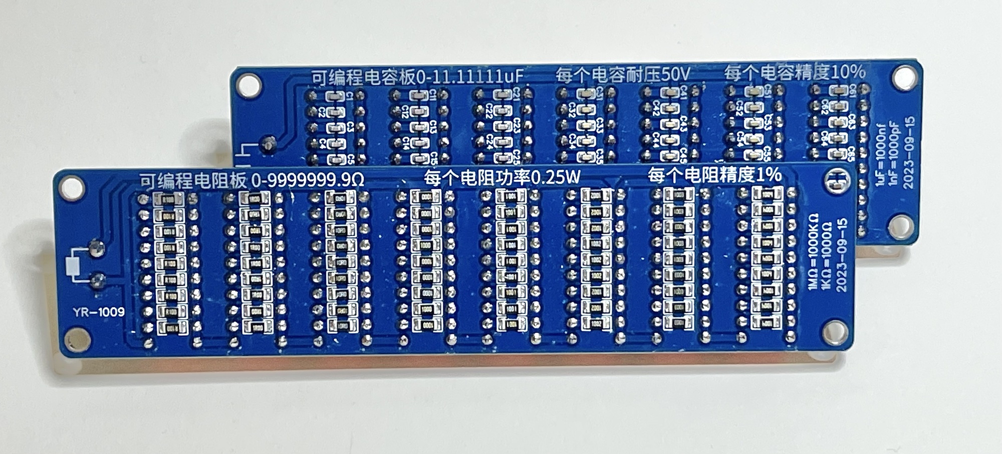
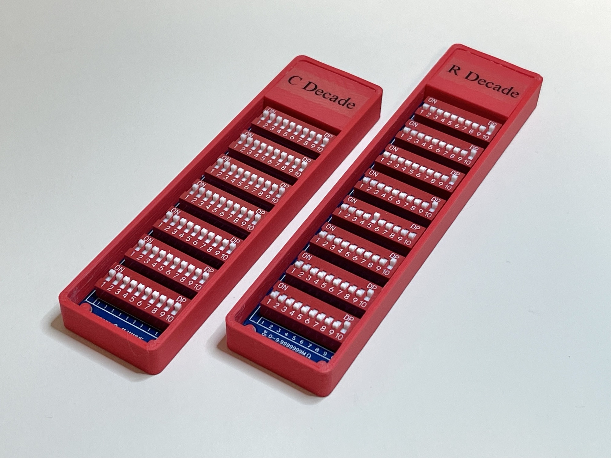
It is of course possible to build a decade yourself, or to just buy one. Usually, however, they are quite expensive things. However, in my search on the site of our Chinese friends, I came across advertisements of very affordable PCBs. Usually the settings were not made with a whole series of switches (as with the more expensive models) but with simple PCB sweaters. However, I also saw versions of very affordable decades with DIP switches. That seemed like a nice intermediate solution. In itself less robust of real switches but a lot less fiddling than with all loose sweaters. And because I certainly do not use such a decade every day, this seemed very useful and affordable. The decade PCBs I ordered are shown below. On the back (middle photo) you can see the loose (SMD) components.
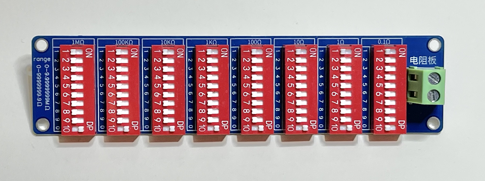
The resistance decade has eight ranges. The smallest range on constructed from resistors of 0.1Ω, the largest range from resistors of 1MΩ. By using the DIP-switches to determine the tapping point of the resistors connected in series per decade, resistance values between 0 and 9999999.9Ω (<=10MΩ) can be achieved in this way.
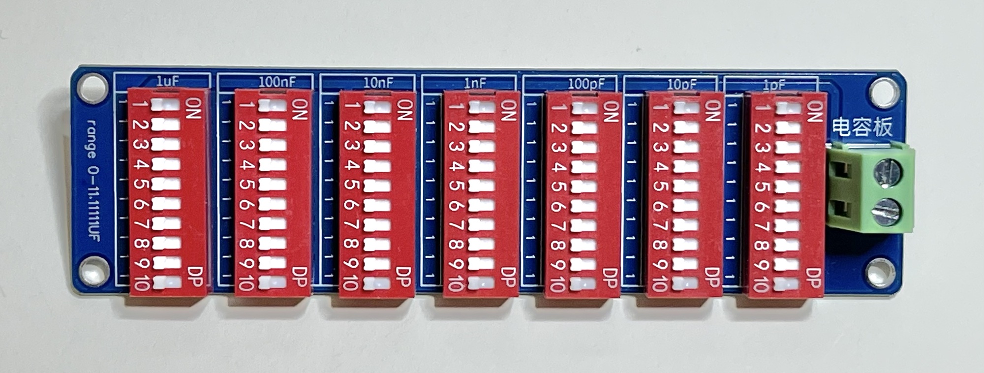
With the capacitor decade, which has only seven ranges, 10 lone capacitors can be connected in parallel per range. The smallest range has 10 capacitors of 1 picofarad each. At the largest range, up to 10 capacitors of 1 μF each can be connected in parallel. Thus, this decade is adjustable between 0 and 11.11111 μF.
The PCBs are directly usable, but I found the green terminal block to be very high above the whole thing. In addition, ideally I have a number of other connection options. For use with a circuit built on a breadboard, I thought a connection option for test leads would be easier. For measuring the set value without unplugging or replugging, I thought it would be nice to have 2mm banana sockets on the final small case I designed for it.
I also made a video of my first tests with both very affordable decade boxes.
Using the decade boxes takes some getting used to. With the resistor decade, a series connection of nine (1%) resistors is made each time, which can be bypassed with DIP switch '10'. With this decade, therefore, ideally one DIP switch per range will have to be selected each time. When all DIP switches are off, it is an infinite resistor. If all DIP switches are set to '10', the resistance is 0Ω (apart from the resistance of the connecting leads and PCB traces).
With the capacitor decade with multiple DIP switches enabled multiple single (10%) capacitor values can be switched in parallel per range. No bypass is required, so there are 10 components per range. What did stand out is that during my test, the minimum value was already about 40 pF. Although this includes the measurement error of my measuring device (and the capacity of the test leads and copper traces), it calls into question the usefulness of the smallest range (with capacitors of 1 pF each). But since the total (theoretical) range (from 0 pF to 11 μF) is quite large, this need not be such a problem. Since an experimentally found value can always be re-measured anyway, the fact that the capacitors have only a 10% precision also does not such a problem.
Perhaps such a decade box with electrolytics might also be an idea. I didn't come across those online yet, so maybe that should be made myself. Configuration with DIP switches I will certainly consider then.