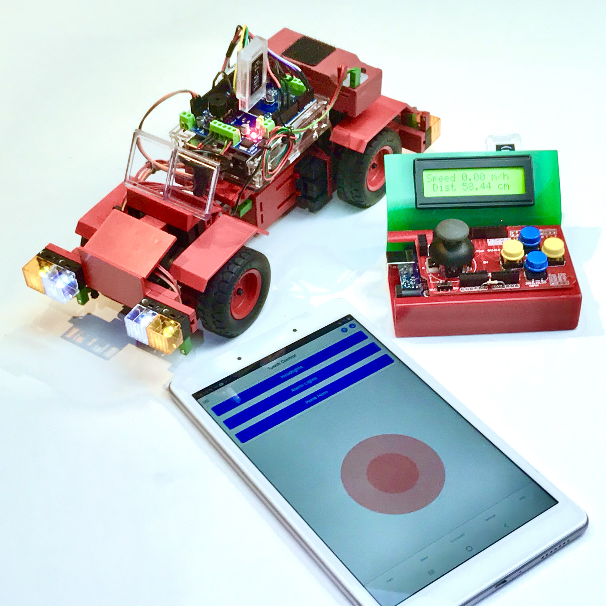
In previous projects universal HF modules where used with the joystick shield to create a remote control unit. With the nRF module a half-duplex connection is possible, but the simple 433 MHz module only allowed data traffic in one direction. On this site I came across the ArduinoBlue app as a remote control for the fischertechnik car. A logical next step is to use a Bluetooth module on the joystick for the remote control.
It turned out to be a lot of information for one project and video, which is why I've cut the subject in two. First, let's take a look at how to establish a full-duplex connection between two Bluetooth modules.
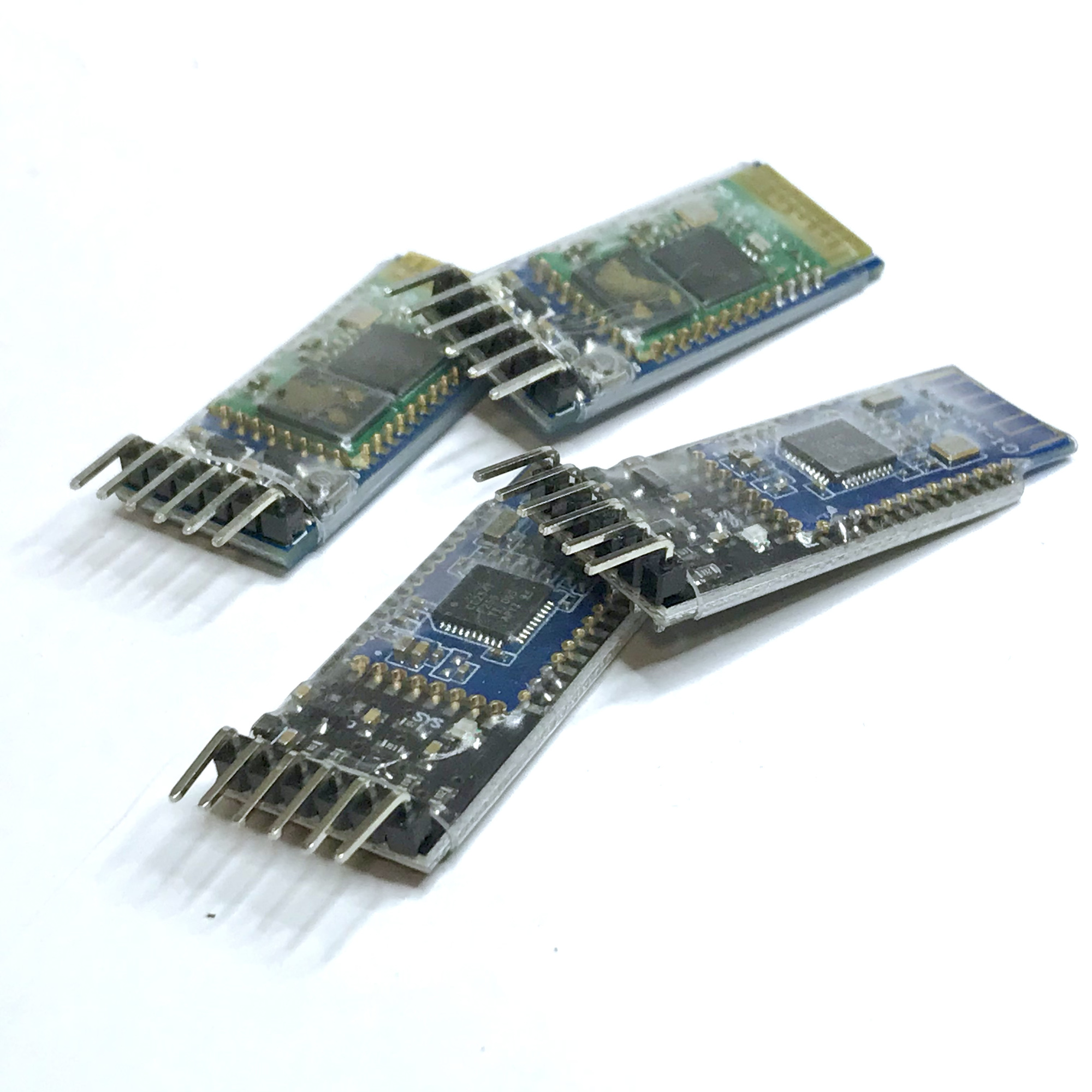
I investigated the following modules:
While testing the modules with the handy apps BlueTerm (Android) or BluTerm (iOS), I soon found out that the HC-05 is not recognized by Apple devices with iOS. This is due to Apple's own MFi Licensing Program that does not support 'Classic Bluetooth' such as used by the HC-05. Dual-mode Bluetooth modules that support both Classic Bluetooth and BLE (Bluetooth Low Energy, from 2009 and Bluetooth v4.0) can therefore only be used over BLE with an Apple device.
The sandwiched PCB structure of these modules is always the same. The actual Bluetooth module is a kind of stamp PCB that is soldered on a slightly larger PCB on with the six connection pins for interfacing with the module. A voltage regulator is included on this underlying PCB in the models studied, so that the supplied supply voltage may usually be between 3.3 to 6 volts. However, please note: according to the datasheet, the HM-19 module may only be powered on 3.3 volt. So always check the datasheet first and use as Vcc for the module either the 5v or the 3.3v pin of the Arduino. Configuring on 5 volt usually does not hurt, but for longer-term operation it would be better to limit to 3.3 volt.
Although a so-called voltage regulator is included for the supply voltage, the maximum input signal for the TX input is often only 3.3 volts. I've not noticed any problems however, while operating these modules with input levels of 5 volts for a short time.
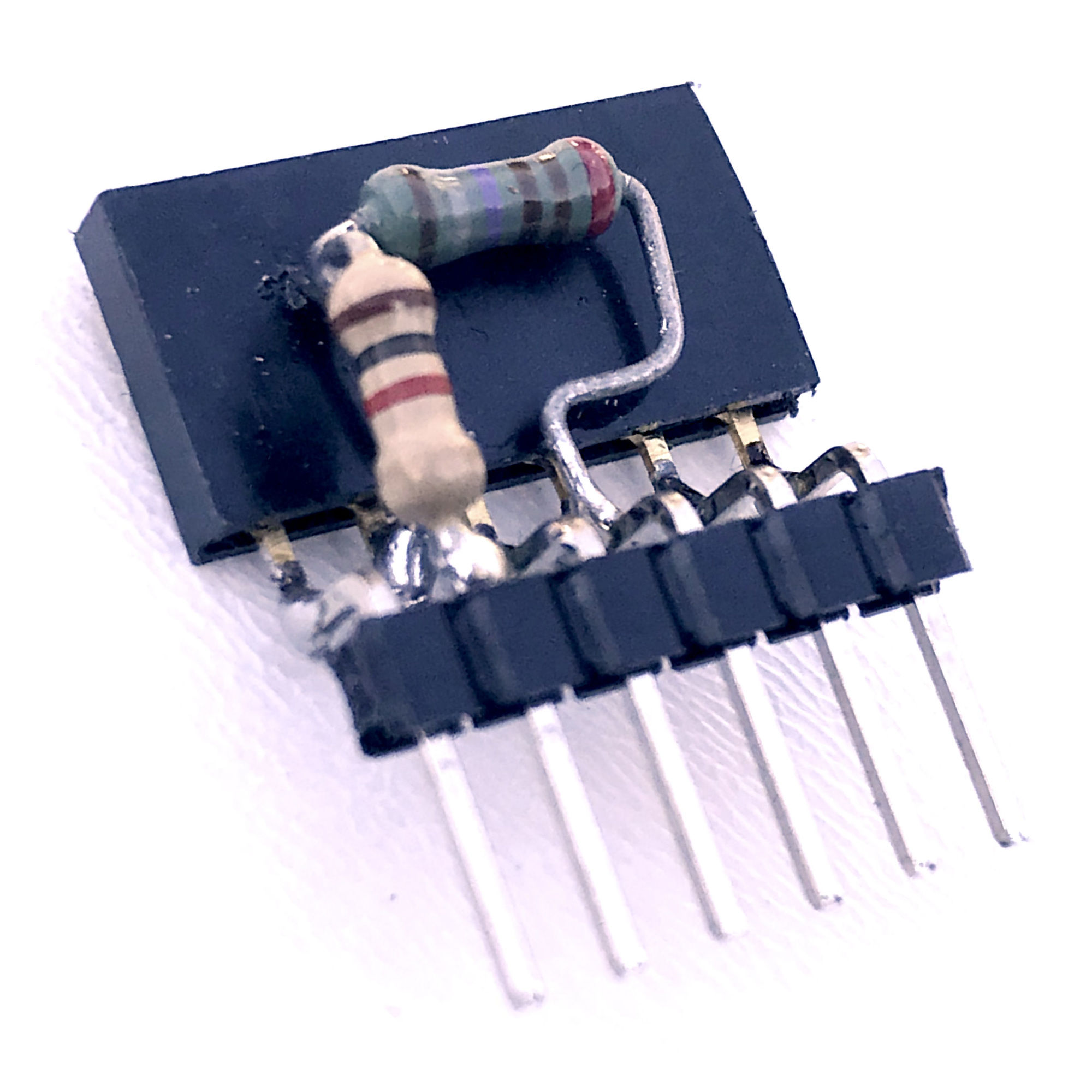
Nevertheless, it is advised (for 5 volt Arduino boards, such as the Uno) to make a simple so-called level-shifter for the TX input of the module. Two resistors will suffice: apply the signal via a 1kΩ resistor and attach the RX input of the module to the GND pin of the socket via a 2k2Ω resistor. In this way a voltage divider is made so that the input signal of the module is neatly around 3.3 volts and the module is protected against out of range input signals.
During configuration and use of the Bluetooth module, the serial TX and RX of the module can be connected to the D0 and D1 of the Arduino (hardware serial). However, because these are shared with the USB connection of the Arduino, this has the drawback that the module has to be removed every time before a Sketch can be uploaded. These RX / TX pins cannot be shared and are only available for one device at a time.
However, by using SoftwareSerial in the Sketch, which allows serial traffic over any two pins of the Arduino, the module can simply be plugged into six adjacent inputs / outputs. By making the Vcc and GND pins HIGH and LOW respectively, 5V supply voltage is also immediately offered. Moreover, the hardware serial remains free.
I made and used the Sketch on the right to set up a connection with the Arduino with Bluetooth module with apps like BlueTerm (Android) or BluTerm (iOS). This worked smoothly with the HM-10 module. By factory default, this module is already set to 'Peripheral' role and could therefore be recognized immediately by the relevant apps.
The Sketch uses SoftwareSerial so the hardware serial remains free for the normal usb connection and the Bluetooth module can be connected to, and powered by, six adjacent pins of the Arduino in one go.
// whizzbizz.com - Arnoud van Delden, 1st february 2021
//
// Configures a BT module connected to pins 8~12 (with optional hardware level-shifter in socket)
// For HC-05 press small button on pcb on power up, HM-10 and HM19 should automatically enter AT-mode
//
#include "SoftwareSerial.h"

// Outcomment line below for HM-10, HM-19 etc
//#define HIGHSPEED   // Most modules are only 9600, although you can reconfigure this
#define EN_PIN_HIGH   // You can use this for HC-05 so you don't have to hold the small button on power-up to get to AT-mode

#ifdef HIGHSPEED
#define Baud 38400   // Serial monitor
#define BTBaud 38400 // There is only one speed for configuring HC-05, and that is 38400.
#else
#define Baud 9600    // Serial monitor
#define BTBaud 9600  // HM-10, HM-19 etc
#endif

#define STATE 8
#define BLUETOOTH_RX 9  // Bluetooth RX -> Arduino D9
#define BLUETOOTH_TX 10 // Bluetooth TX -> Arduino D10
#define GND 11
#define Vcc 12
#define ENABLE 13

SoftwareSerial bluetooth(BLUETOOTH_TX, BLUETOOTH_RX);

void setup() {
  // Setup BT module
  pinMode(BLUETOOTH_TX, INPUT);
  pinMode(BLUETOOTH_RX, OUTPUT);
  pinMode(STATE, INPUT);
  pinMode(GND, OUTPUT);
  pinMode(Vcc, OUTPUT);
  pinMode(ENABLE, OUTPUT);
  digitalWrite(GND, LOW);       // Ground for BLE Module
  digitalWrite(Vcc, HIGH);      // Vcc for BLE Module
#ifdef EN_PIN_HIGH
  digitalWrite(ENABLE, HIGH);   // Used to force AT-mode for HC-05. More flexible is to press the button on the pcb
#endif

  // Start serial communications.
  // The baud rate must be the same for both the serial and the bluetooth.
  Serial.begin(Baud, SERIAL_8N1);
  bluetooth.begin(BTBaud);
  Serial.println("Bluetooth available.");
}

char c;

void loop() {
  // From BT-->Serial
  while (bluetooth.available()) {
    c = bluetooth.read();
    Serial.print(c);
  }

  // From Serial-->BT
  if (Serial.available()) {
    while (Serial.available()) {
      c = Serial.read();
      Serial.print(c);
      bluetooth.write(c);
    }
  }
  delay(100);
}
If we want two Bluetooth modules to communicate with each other, one may remain in 'Peripheral' mode but the other will have to be configured as 'Central' to take over the role of the smartphone or tablet with the ArduinoBlue app.
With the 6-pin foot with built-in level shifter, the module can directly connect to the digital inputs / outputs D8 (State), D9 (RX), D10 (TX), D11 (GND), D12 (Vcc) and D13 (Enable). The outputs D11 and D12 are set to 0 (LOW) and 5 (HIGH) volts respectively so that the module receives its power supply. Most modules automatically go into AT mode, but on the HC-05 a small button has to be pressed during power up. However, I found out that this mode can also be forced if the D13 (EN) pin is held high in the configuration Sketch.
Except for the HC-05, all modules have a default baud rate of 9600 baud. This could optionally be changed to 38400 (8N1). After all, all modules support baud rates of 9600, 19200, 38400, 57600, 115200, 230400 and even 460800 baud. For one module I accidentally configured the number of stop bits to two. As a result, the module was no longer accessible via SoftwareSerial. An additional problem was that SoftwareSerial of the Arduino unfortunately does not support configuration of the parity and stop bits. Fortunately I was able to 'rescue' this module (interactively by AT commands via hardware serial) with an Arduino Mega. This board has the advantage that it has four hardware serial RX / TX interfaces, of which the parity and the number of stop bits can be adjusted.
In addition to the lower power consumption, Bluetooth BLE with the more modern HM-10 and HM-19 modules has another advantage. As soon as such a module is placed in the 'Central' role, it automatically starts scanning when it is switched on so it can establish connection with the 'Peripheral' module automatically. With the HC-05, the Mac address of the 'Central' must be entered manually (once) with the AT command AT+BIND to the 'Peripheral'. Below I have included some useful AT commands for configuration per module.
The HC-05 is a Bluetooth V2.1 module, which should be compatible with the HM-15. The module is second generation Bluetooth. Communication with smartphones and tablets, which nowadays mostly focus on BLE support, is not always possible. For example, an app like ArduinoBlue cannot be used because it simply does not recognize the entire module. The Bluetooth Electronics app, only available for Android systems, can however be used.
Of course, there is no problem in using classic Bluetooth for communicating with a DIY physical remote control (such as the joystick shield), but being able to control your model or robot by an app on an iOS smartphone is of course also attractive. Due to restrictions of the the MFi Licensing Program this is however hardly possible under iOS.
So, however classic Bluetooth may be useful for wireless transmission of (sensor) data, for a remote controller it would not be the most universal choice. I still researched it because the traditional master-slave model of classic Bluetooth (which has been redesigned in BLE to a more universal, but for simple applications sometimes superfluous complex, central-peripheral model) is still suited for simple control in which simply text and numbers need to be exchanged using a text protocol.
From the HC-05 datasheet and the AT+UART? command it turned out that the baud rate is set to 38400 by default, and not to 9600 as with most BLE modules. So, to communicate with the module with AT commands, the SoftwareSerial had to be set to 38400. I tried (with the command AT+UART=9600,0,0) to adjust this, but it failed. The module did respond to operate at 9600 baud, but it still seemed only to be reached on 38400 baud. Since BLE got my attention, I did not investigate much further.
Hold down the small button on the board of the module while applying the power supply to the Arduino with the configuration Sketch. The LED on the module will now flash slowly and the module will accept AT commands. Set the serial monitor to 38400 baud and NL / CR line ends. I checked and changed the baud rate of both modules, respectively with the commands AT+UART? and AT+UART:38400.0.0.
Write down or copy the MAC address of the slave module that can be queried with AT+ADDR?. Check whether the role of this module is 0 ('Slave') with AT+ROLE?.
Now the module is swapped with the second module, do not forget to hold the small button when applying the power supply so that the LED flashes slowly and the module starts in AT mode. If desired, change the baud rate with AT+UART: 38400,0,0 and set the role of this module to 1 ('Master') with AT+ROLE1. I also made a foot where the D13 can be kept EN (enable) HIGH. This forced the AT-command mode on my HC-05 and the button does not have to be pressed at start-up. However: to return to normal operation, this output must be made LOW again! Because most other modules expect this pin to be HIGH (or simply not connected), this is something to be aware of.
Now the 'connection mode' of this module can be set to one fixed address with AT+CMODE=0, after which the automatic binding with the MAC address of the Slave module can be made with AT+BIND=[MAC]. Note: I had to replace the colons returned in the MAC address of the Slave module with commas with this command. It is all a bit of a puzzle, but in the end it worked.
After placing and resetting a module in each of the two Arduinos, a text connection is now automatically established between the two serial monitor screens at 38400 baud. I tried this with two different computers: what is typed into one serial monitor appears almost immediately in the other.
My AT-09 Bluetooth V4.0 BLE module is probably the DX-BT05 and reports as BT05. On closer inspection it turns out to be a clone of a clone of the HM-10 module. In principle, the price is accordingly. The actual AT command set was quite a puzzle. Some of the AT commands from the original HM-10 datasheets worked (or the closing '?' had to be omitted for the same result) and eventually I managed to automatically connect a module in 'Central' role to a module in 'Peripheral role. However, (text) data traffic in both directions did not work. For a moment it did in one direction, however. The module was succesfully recognized by BLE scanners and I was able to communicate with it with, for example, BlueTerm.
AT+BAUD? returns 4. And according to a document found online, this should represent 9600 baud. Ideally, this would rather be 2 = 38400 according the datasheet. But after AT+BAUD2, the module (after much trial and error) appears to only respond to 'AT' at 2400 baud. Other commands no longer work and so the module became unusable.
Also the command AT+RENEW to return the module to factory settings could no longer be given and because I had apparently made two modules unusable in this way, I decided to try to update the firmware. I found instructions (and success stories) to make the module into an HM-10 at https://forum.arduino.cc/index.php?topic=393655.0
This seemed to go pretty well in itself, the downloaded firmware would directly upload the HM-10's original firmware into the modules. Unfortunately, the modules were unusable after that because they no longer responded to AT commands at any baud rate. After reading through some forums, it turned out that more people became the victim of this. Fortunately, the purchase price of these clone modules is not high, so I decided to take my loss, ordered some 'real' HM-10 modules, and in the meantime focused on the HM-19 modules.
The easiest pairing of two modules can be achieved if they can both be activated at the same time, each in its own Arduino. You can use the above Sketch in two seperate Arduino's for this.
When using the special configuration foot (whereby the 'Enable' on D13 may be left loose, or kept HIGH), the module starts in the AT command mode. I set the baud rate of both modules (with AT+BAUD5) to 38400 instead of the default speed of 9600 baud, but this is basically not necessary. Moreover, this is only the communication speed between the module and the Arduino (not the speed that the module uses at 2.4GHz over air).
The module in the joystick shield gets the 'Central' role with the command AT+ROLE1 and the module in the model to be controlled can remain 'Peripheral' (AT+ROLE? Gives 'OK + Get: 0'). Write down the MAC address of the 'Peripheral' (with AT+ADDR?). This is because the 'Peripheral' module can soon also be linked by MAC address if it is difficult to activate it simultaneously in another Arduino during the configuration of the 'Central'.
The 'Peripheral' module can now be removed. Now we plug in the module to be configured in 'Central' role. Linking with the scanned index is easiest, but this requires that the other module (e.g. in the model to be eventually controlled) is switched on and is detectable during the discovery scan. It is also necessary to turn off the automatic scanning / discovery of the future 'Central' module with AT+IMME1. Then make this module the controller with AT+ROLE1. Now you can let the module scan or 'discover' as 'Central' with AT+DISC?. A list follows of the discovered 'Peripheral' modules where the number for the desired module is important. Suppose the index of the desired module is 2, then the link can be established with AT+CON2. Finally, the 'Central' module must be returned to autodetect / -connect mode with AT+IMME0.
After resetting both modules (or giving AT+START to the 'Central'), the connection should be established automatically!
The ArduinoBlue app on the smartphone will connect to the Bluetooth module in the model with factory settings right away. By using the ArduinoBlue function library in the Sketch for the controllable model, it can be controlled quite easily with ArduinoBlue from an iOS or Android smartphone or tablet.
If a physical joystick control (such as a joystick shield) can also be made compatible with this, and can take over the role of smartphone or tablet with ArduinoBlue, the controls are interchangeable and the model can be controlled in two completely different ways.
The experiments in that direction are discussed in part two of this project.