
Some time ago I described a module with multiple voltage outputs (12, 9, 5 and 3.3 volts) and a display showing the power and current consumed per output. I use this to power fischertechnik models. However, the current readout and adjustable fuse of that module are not necessary for fully developed models that remain assembled for a longer period of time. Because soon all the modules I built of this type were in use, I thought it would be useful to also develop a cheaper and easier to build alternative to this module.
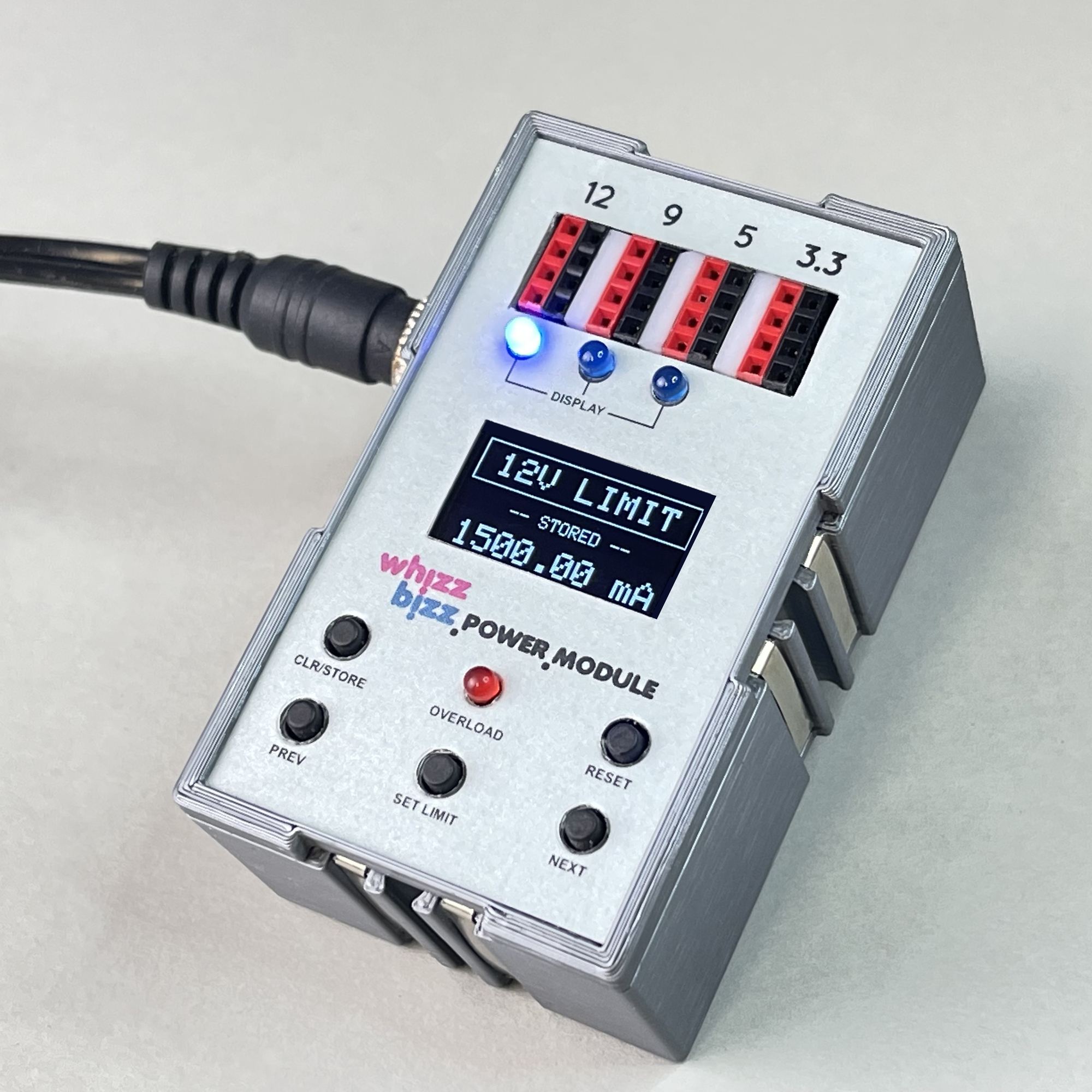
On the photo the previously discussed module. The module is powered with a universal 12 volt DC adapter with the common DC plug with a diameter of 5.5 mm (with 2.5 mm pin for the positive pole). The development of this module presented me with quite a challenge. Ultimately, two stacked printed circuit boards with SMD technology were needed to get all the functionality into the self-3D printed Silberling housing.
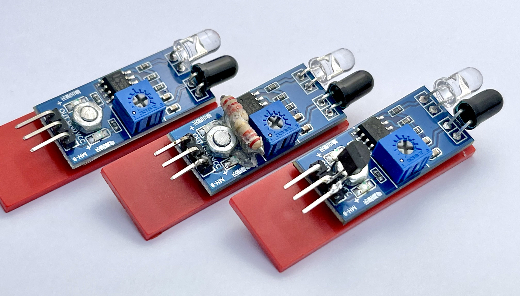
In any case, this module fulfilled, in addition to the usual fischertechnik 9 volt 'consumer' voltage during experiments with the classic fischertechnik electronics modules, the wish to use the many interesting and nowadays dirt-cheaply available 'breakout boards' for controlling models. Many of these 5 volt sensor boards, such as the LDR, IR obstacle and Hall effect sensors, have a simple logic output that can even be used with 'vintage' electronic modules like the fischertechnik 'Silberlingen'.
Sometimes the modules can be used on 9 volts after a minor electronic modification, but it is easier to have a 5 volt supply voltage available immediately. When using the modulair Flipflop and Monoflop electronic modules, but also with replica modules with CMOS technology at 9 volts, the output signal of these boards, which alternates between 0 and 5 volts, can be used as a logical digital input signal without any problems.
My DIY CMOS modules are very forgivable in terms of supply voltage. In practice, it is not even a problem to run them on 5 volts. But because I had already opted for a separate connection field with three-pin plugs for sensor boards with which they could be supplied directly with 5 volts, I decided to maintain a higher supply voltage for transmission via the metal strips on the sides to the existing fischertechnik modules. . So ideally the module should be able to supply two voltages, 5 volts and a 'working' voltage of 6.8 ~ 9 volts respectively.
Because I wanted to realize a loop-through option for the input voltage on the back of the module, just like with the Zauberling (see photo of the back), it would be nice if both a 9 volt and a 12 volt DC adapter could be used as needed. are used. A low supply voltage is sufficient for purely logical experiments with the digital Silberlingen, but it is nice to have a higher supply voltage available for an amplifier stage or H-bridge if larger consumers such as motors or light bulbs are used elsewhere in the circuit.
The obvious option is to equip the module with the common linear voltage regulators from the LM series (LM = 'linear monolithic'). However, these regulators have a so-called 'Drop Out voltage'. The stable output voltage will always be this voltage threshold (about 1.7 to 2 volts) lower than the input voltage. If a 9 volt DC adapter must also be used for the input voltage, the output voltage of the module is therefore limited to about 7 to 7.5 volts. Apart from the fact that there is no LM7807 to directly produce this fixed output voltage, when feeding with a 12 volt DC adapter, considerable heat development can occur in this voltage regulator, even at low currents, because the five volt voltage drop at average currents already generate considerable power that must be dissipated as heat.
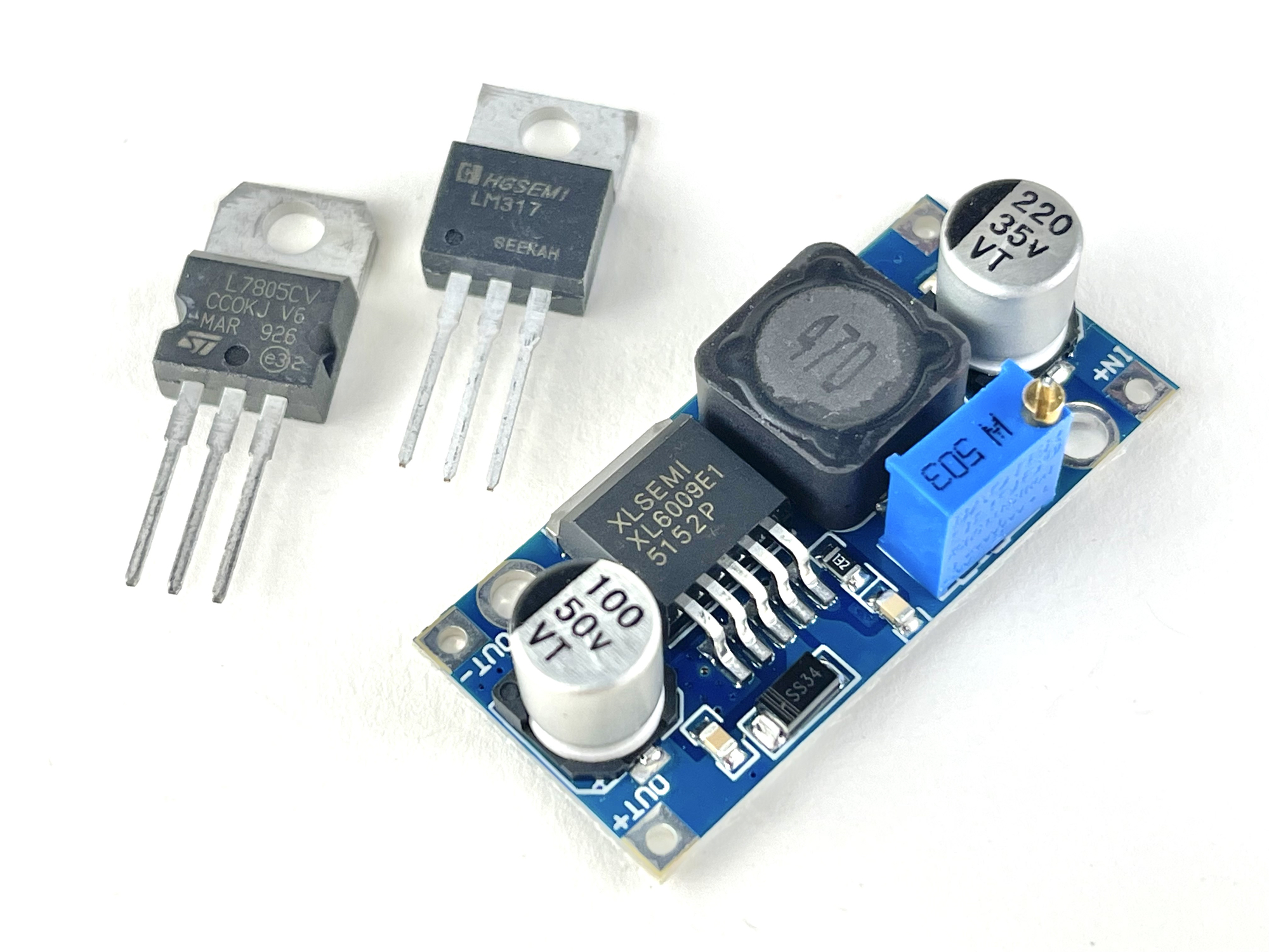
A more efficient choice may be a so-called DC-DC step-up power module with, for example, an XL6009 or LM3577 regulator. Although it would be quite possible in terms of dimensions to accommodate two of these modules in a Silberling housing, there are other disadvantages. For example, the output voltage of these so-called step-up/down (Boost/Buck) converters is not as stable as that of traditional LM regulators and they will generate more Electromagnetic Interference (or EMI). This can be disruptive, especially for digital circuits with a clock signal, if there is insufficient filtering. A frequently mentioned problem is that these 'boost modules' can become quite warm without connected consumers. However, mounting a heat sink on these controllers is hardly possible due to the fully soldered housing.
The newly developed module will mainly be used to feed the digital logic, and perhaps occasionally the original fischertechnik Silberlingen, of models. Nevertheless, it is nice if both a 9 volt and a 12 volt DC adapter can be used and that the input voltage of the adapter can be looped through at the back to external consumers or other modules that can use this higher input voltage usefully (such as a future develop H-bridge module for controlling motors). The voltage of 3.3 volts of the Power Module from part 1 required specifically for microcontrollers can be omitted in any case. Current measurement and automatic fuse are of course also not a requirement for this simpler power supply module.
In summary, the requirements for a newly developed power supply module are:
Ultimately, I came to the conclusion that the module printed circuit board to be developed would preferably be designed so uniformly that modules could be made with, in addition to the fixed 5 volts for the sensor boards, output voltages of 7.5 or 9 volts. The lower 7.5 volt output voltage is sufficient when a logic circuit mainly constructed from Silberlingen is powered. As mentioned above, a sensor output with a 5 volt signal level is sufficiently detected as logical 'HIGH' (or in the negative logic of the traditional Silberlingen as logical 'LOW'). The option of also using a 12 volt DC adapter is useful if heavier consumers such as motors are used. In that case, the 12 volt adapter voltage provides 9 volt working voltage for the module and the 12 volts can be looped through at the back of the module to other self-built Silberlingen or external users.
To create the 5 volt 'sensor board' voltage, the use of an LM7805 is obvious. To create the 7.5 or 9 volt output voltage, a voltage regulator on the circuit board can be set. The choice fell on the LM317 for this. Like the LM7805, it is a so-called linear voltage regulator, but unlike a fixed output voltage, the LM317 offers an output voltage that can be adjusted by means of a resistance ratio. Although this is not very important for this project, a small advantage of the 'low noise' LM317 over an LM regulator with a fixed output voltage is that it introduces slightly less noise and ripple on the output voltage and also with higher currents ( >1.5 A) can be used.
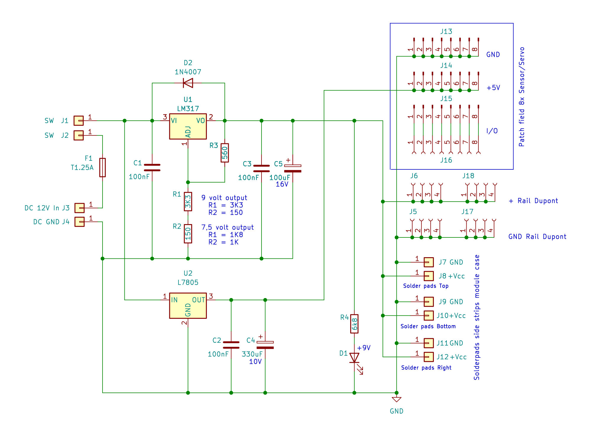
The electronic diagram is visible above. With the resistance values shown for R1 and R2, the output voltage of the LM317 is set to 9 volts. By changing R1 to 1K8W, and R2 to 1KW, the output voltage will drop to 7.5 volts. The input voltage may be a maximum of 35 volts, but in practice it should be chosen as low as possible, but in any case 2 volts more than the intended output voltage.
In practice, the 7.5 volt module can also be operated with a 12 volt DC adapter. However, depending on the current, slightly more heat development may occur. In an emergency, the 9 volt module could even be powered with a 9 volt DC adapter. However, due to the so-called 'Drop Out voltage', this module will only provide an output voltage of approximately 7 volts, comparable to the 7.5 volt module when it is powered by a 9 volt DC adapter. However, the regulator output voltage will not be stable under these conditions, but since it will not exceed 9 volts, it cannot do much harm.
By using the LM317 it is in principle possible to make the module switchable on the front plate. Yet I did not choose this. I thought it would be easier to simply make different versions of the same module using the same PCB design. Because at about the same time I came across the solderable PCB sockets for fischertechnik plugs described elsewhere on this site, I also decided to make two different PCB designs: one for Dupont plug strips, and one with which modules could be built on which the classic 2.5 mm fischertechnik plugs can be used.
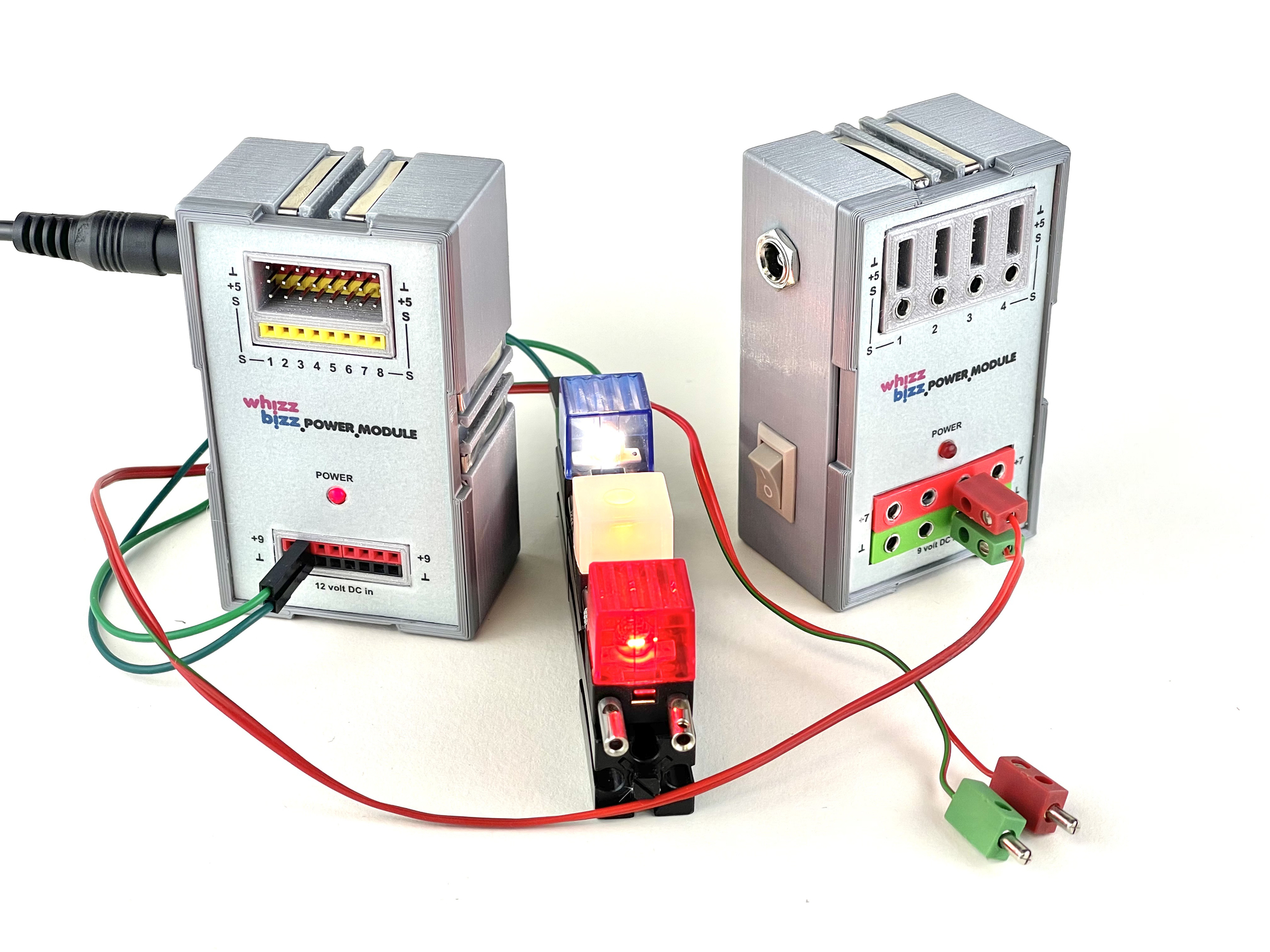
Because I had already decided to build modules with two output voltages (7.5 volts when using a 9 volt DC adapter and 9 volt output voltage when used with a 12 volt DC adapter), this ultimately resulted in four different types of modules. However, the sockets for the fischertechnik plugs take up more space on the front plate than the Dupont header mouldings. As a result, the connection option for four sensors and four red +9 and green 'ground' connections can be realized on this module, while eight such connection options could be realized on the module equipped with the Dupont headers.
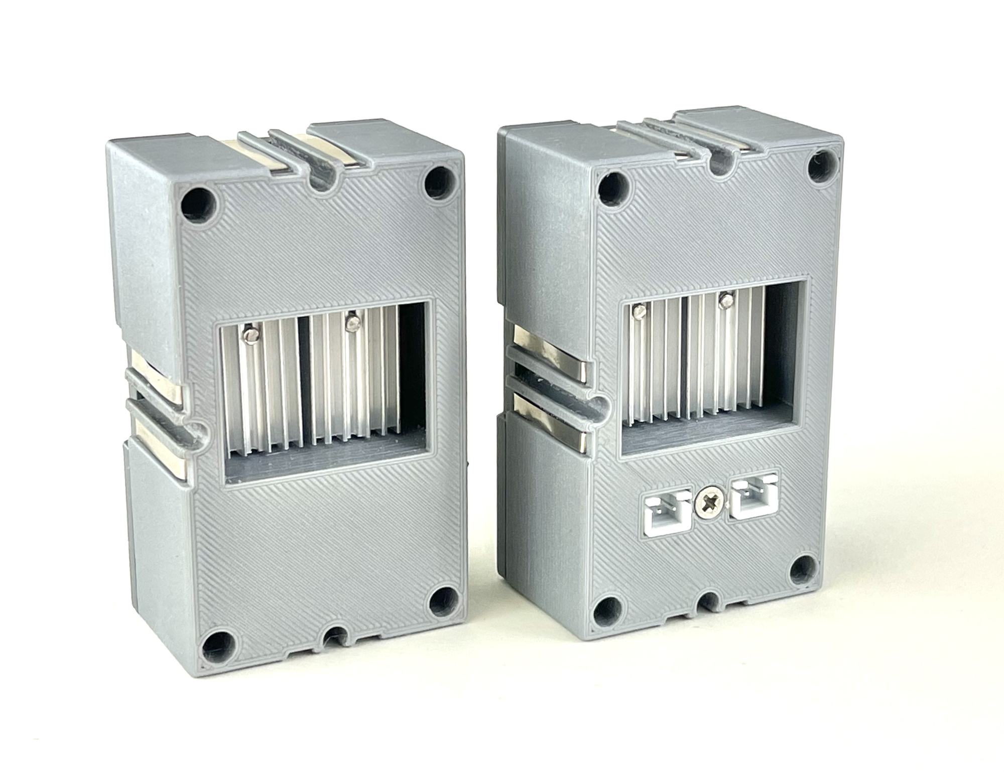
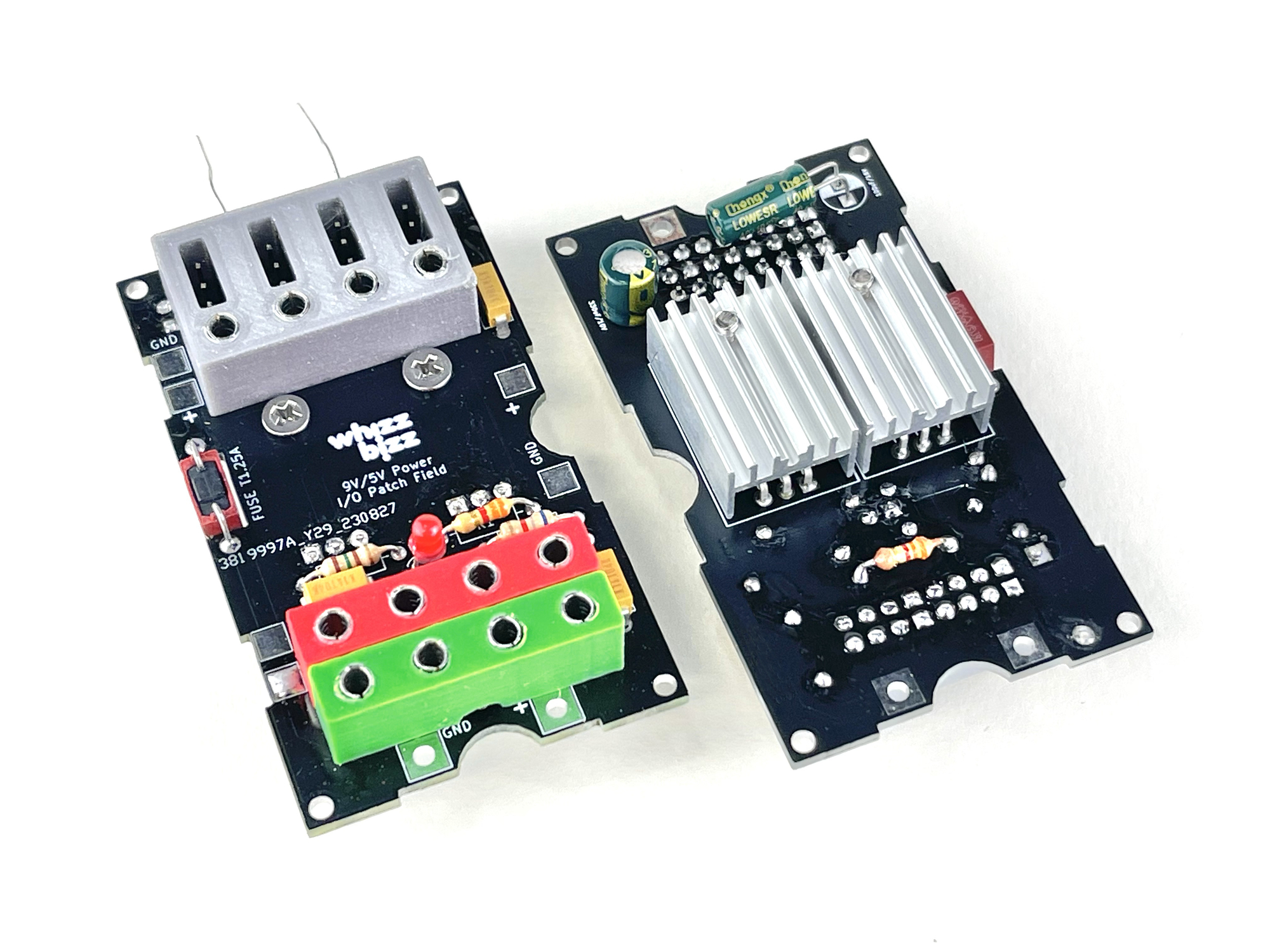
The modules are built into a 3D-printed Silberling-compatible housing. However, unlike the previous 'Power Module', this time the design could be completely accommodated on one printed circuit board. This allowed the heat sinks of the voltage regulators to be housed inside the housing. An opening in the back provides sufficient air cooling. The two optional JST-XH connectors for daisy-chaining the incoming power supply were housed on a small separate printed circuit board. Not every module needs these connectors on the back and in such a case a housing without these two openings can simply be printed.
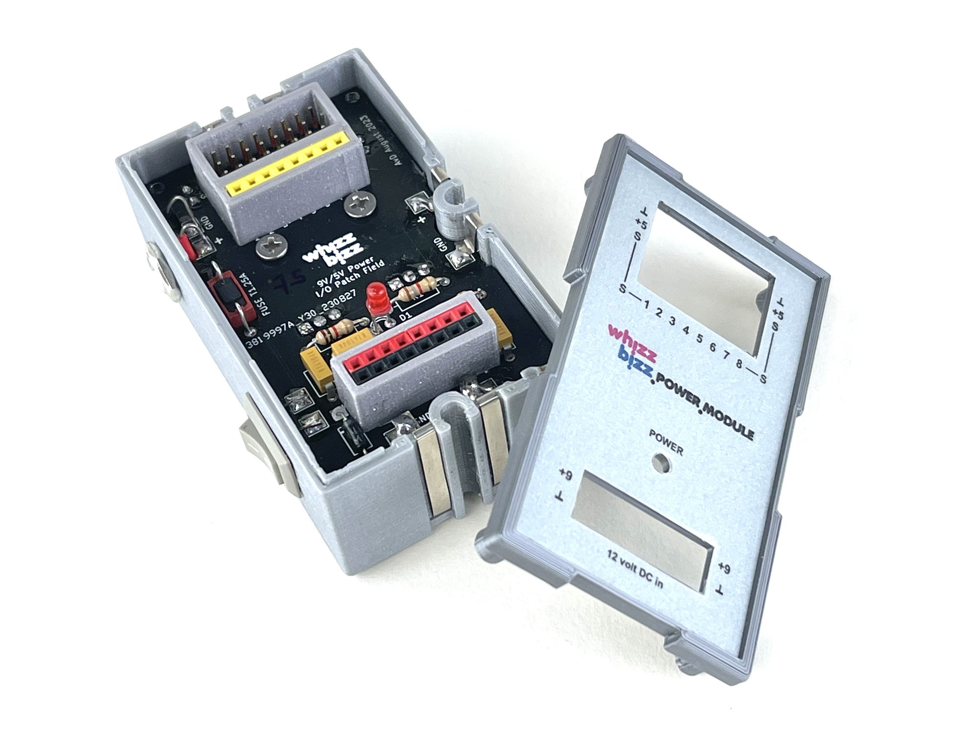

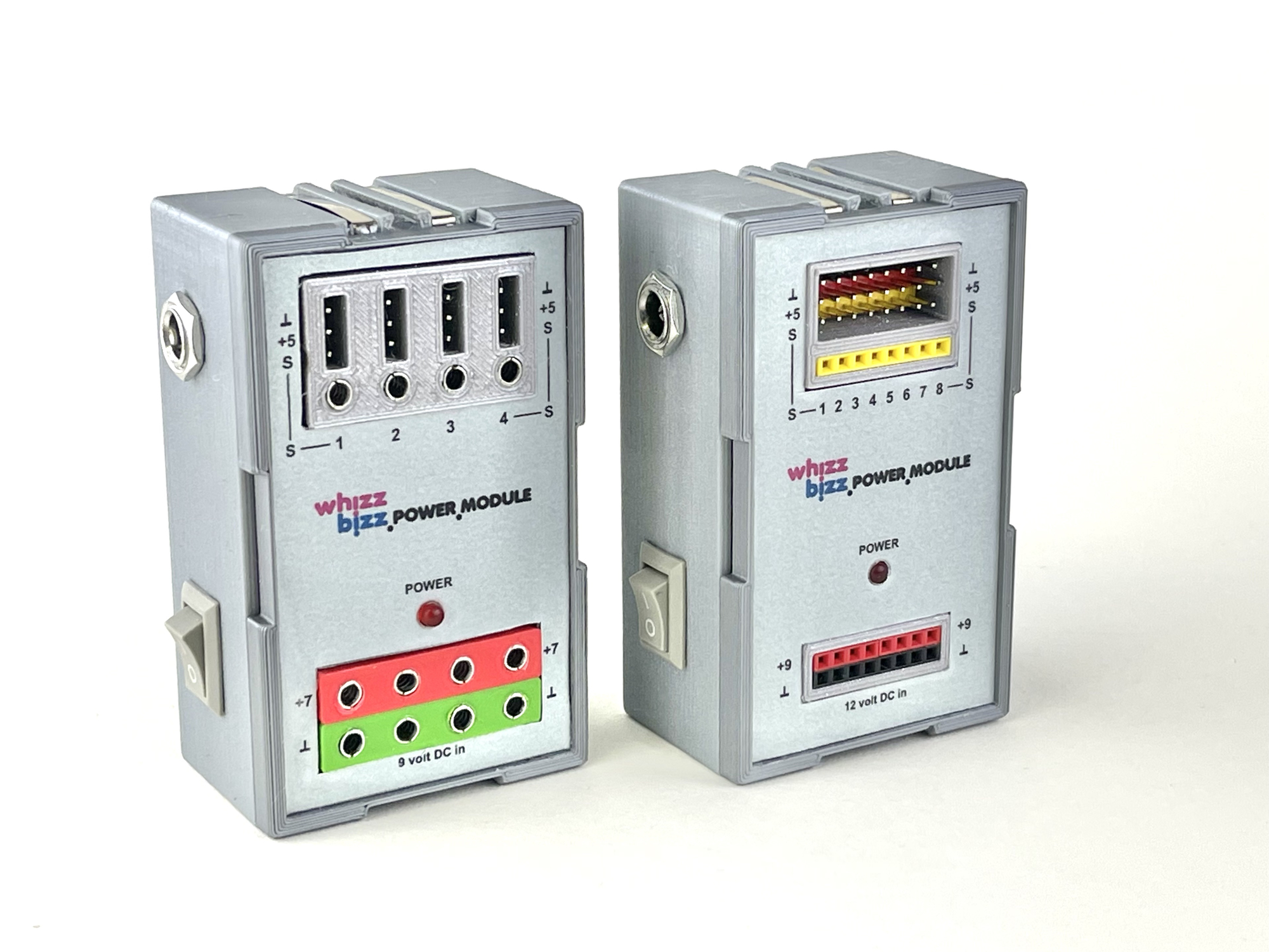
The connector lists for the PTN2-10 cable lugs were printed in color. They ensure sturdy mounting and minimal strain on the printing islands when inserting and removing the plugs. The connection blocks protrude through the front. For the design of the front panel, the positions of the various front elements were taken directly from the 'Silk Screen' design from the design program (KiCad) into the drawing program (Affinity Designer 2), printed on a laser printer and then laminated with a matte laminate foil . After cutting and punching, the resulting front plate is ready for gluing to the housing cover. Both plug variants are visible side by side in the photos above.
All types of modules have now been built and are already in use to my full satisfaction. Several of the previously discussed extensive programmable 'Power Modules' could now be 'reclaimed' from models and have been exchanged for this simpler variant.
I am considering building a small batch of these modules for third parties. But for those who want to build such modules themselves, I am happy to provide all the information required for construction. As usual, I am open to suggestions and anyone interested in the module can contact me. The 3D STL files used for the power rails can be freely downloaded.