
On the other project pages, various non-contact switches were already discussed. The starting point was that these can also be used in circuits built with the classic fischertechnik electronics modules, also called "Silberlingen. Meanwhile, I experimented with the supply voltage and signal output level of some other sensors such as the IR-obstacle, LDR, Hall-Effect and PIR motion sensors. The fact that these sensors can sometimes already be operated directly on 9 volts with a relatively small adjustment makes them in principle already suitable for use with the microcontrollers (such as the fischertechnik 'TXT controller') that operate on this higher supply voltage. Thereby, the output often even turns out to be already suitable, or easily made electronically compatible, for direct use on the vintage 'Silberlingen' for more conventional electronics experiments.
I experimented with some sensor modules that can easily be bought online for little money and are already equipped with a differential amplifier or Schmitt trigger that provides steep signal slopes around the switching level. The output signal from these boards can be used directly without interference in synchronous circuits. Therefore, even in the applications presented here where classical "Silberlingen" are used, the "unpruning" of any switching noise is not necessary.
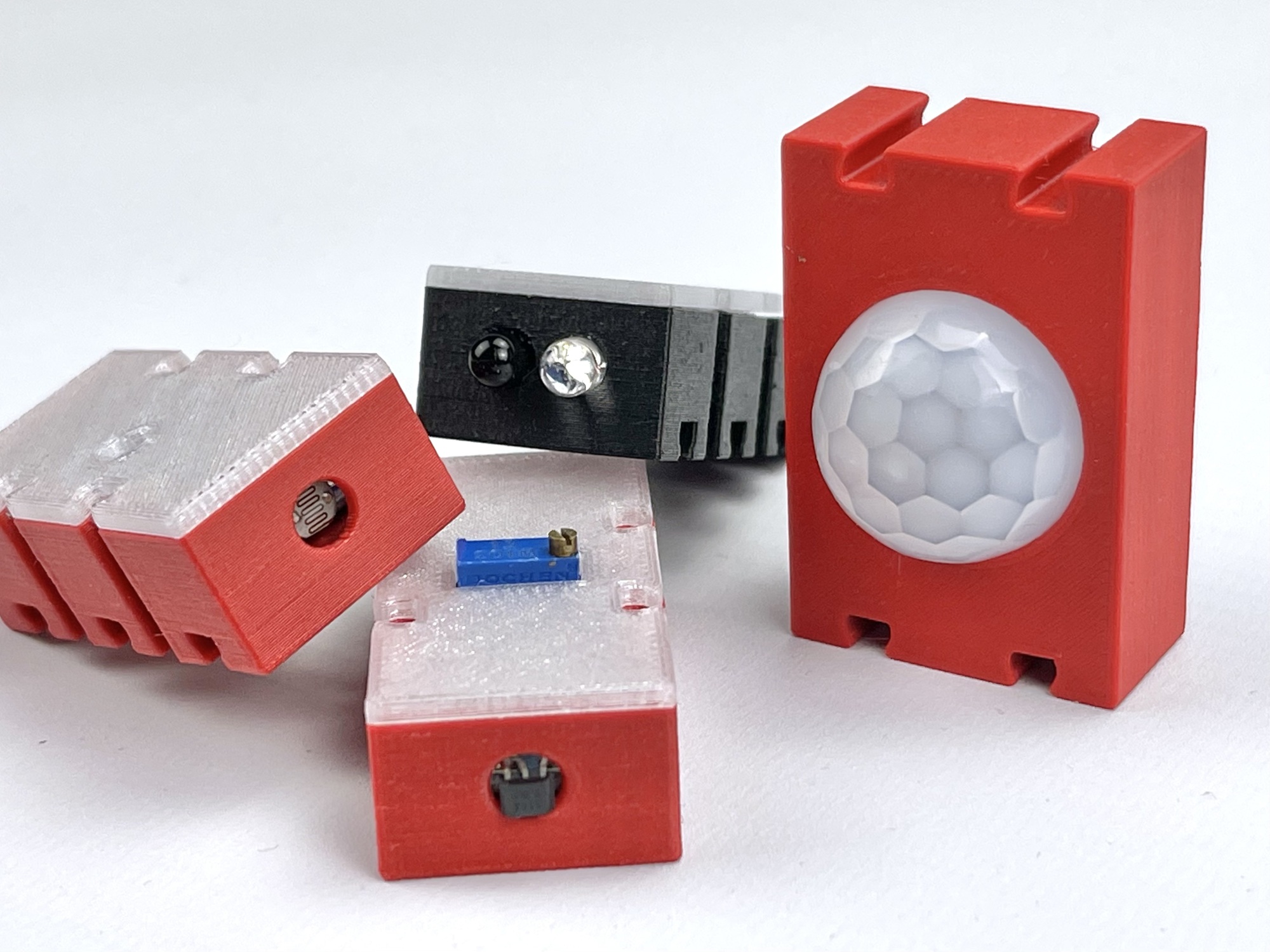
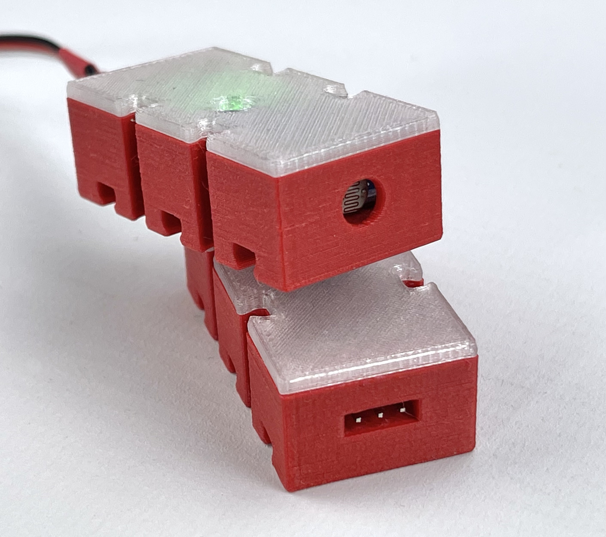
Three of the sensors discussed here could be accommodated in a small (22.5 x 15 x 45 mm) housing of which I designed different versions for connection with a flat 3-pin (Dupont) plug and with sockets for use with the well-known fischertechnik plugs. In addition, I experimented with different lid types. I later replaced the closed lid with a transparent diffuser that serves as a window for the detection LED on the board. If the housing is printed with red, this visually aligns nicely with the electronics modules from the fischertechnik program.
A very useful sensor that I have been experimenting with for some time is the IR obstacle sensor (HC-SR501). Like most other sensor boards, this one expects a supply voltage of only 5 volts in its basic version. The small sensor board already has a 3-pin "male" connector soldered on one side. Unfortunately, the pin sequence of this is not standard. Whereas on 3-pin servo leads the + is cleverly positioned in the middle (to prevent polarity reversal and damage when reversed), on this sensor board the 0 volt (GND) is positioned in the middle.
To bring the sensor into the 9 volt domain of the fischertechnik modules, a number of possible modifications were discussed in the past. Because the LM393 differential amplifier used on the board can in principle already handle a supply voltage of up to 36 volts, use at 9 volts theoretically does not even pose a very big problem.
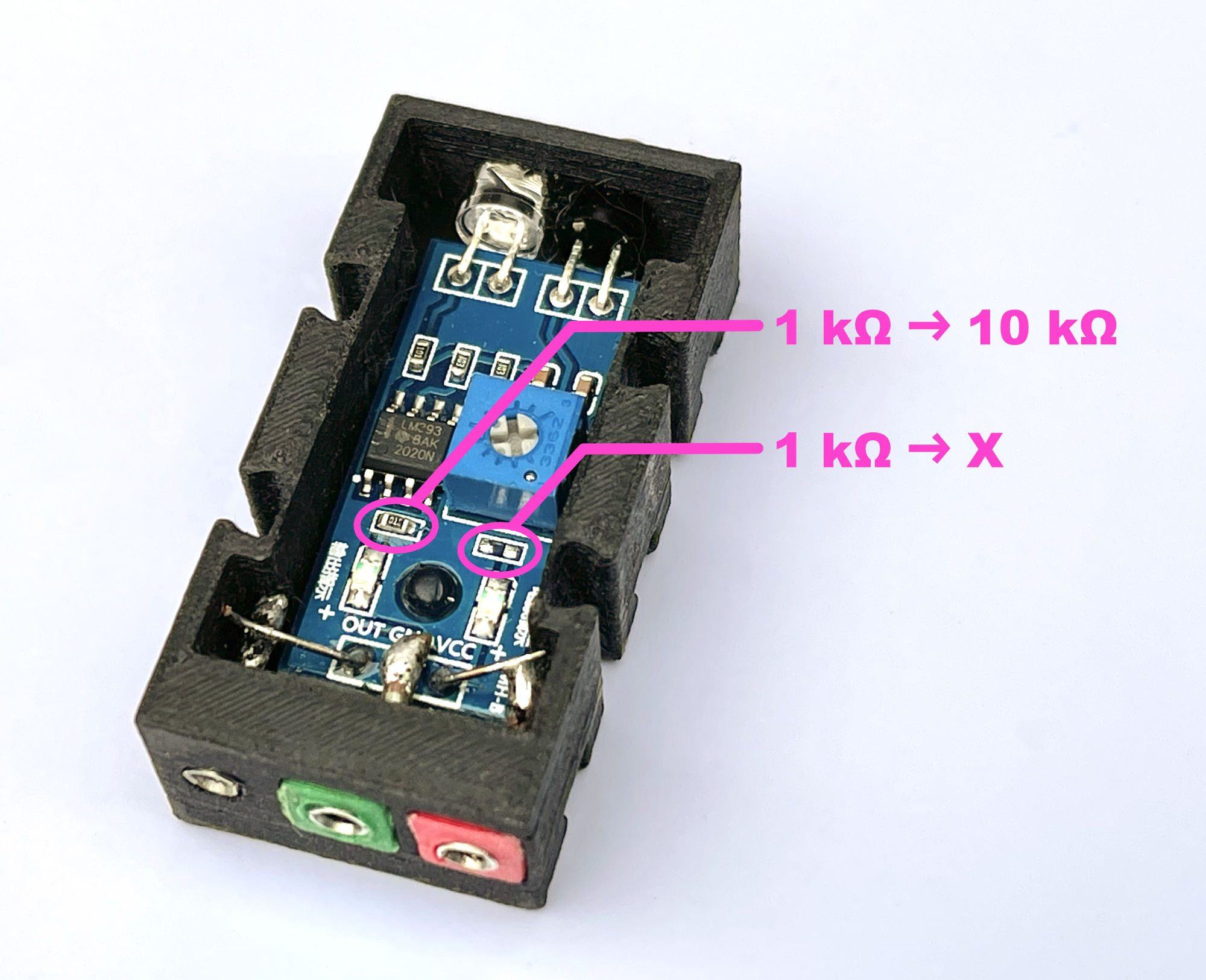
However, there are two very bright red "low current" SMD LEDs on the board that are provided with a series resistor of 1 kΩ. One LED lights up as soon as the supply voltage is connected and the other when detected. Understandably, these LEDs do burn very brightly at 9 volts (and are not even expected to last long). I solved that by removing both ballast resistors and giving the detection LED a new 10 kΩ SMD ballast resistor. In principle, at least some 4k7Ω is sufficient, but this way we still have some headroom towards the 12 volts for application to the Silberlingen. This is because the LEDs burn bright enough even at very low currents. Soldering the new resistor with SMD footprint 0603 is a precision job, but can be done without special hot-air soldering equipment.
Because the sensor functions perfectly well on 9 volts after this modification, it can be used with both the TXT controller and the 'Silberlingen' without any problems. The output can be connected directly to the inputs of the'Silberlingen' because the LM393 used, with its 'open collector' output, has no trouble at all with the negative logic and conventional electronics of these classic electronics modules. Thus, the sensor output can also be used directly in circuits built with the several 'Silberlingen' modules.
When powered by 9 volts, the output signal is virtually the supply voltage. This drops to zero volts upon detection of an object within the, via a hole in the cover adjustable, detection distance. The switching behavior thus conforms to the negative logic of the 'Silberlingen'.
As with the sensor described above, we find the LM393 here as a differential amplifier. The switching pulse of the output signal is therefore nicely steep and, due to the lack of switching noise, can also be used directly as a digital clock pulse. As already touched upon, this is a very nice feature of these non-contact switches.
The Hall-Effect sensor is built around the 3144 Hall sensor which can basically handle a supply voltage between 4.5 and 24 volts. Therefore, like the IR obstacle sensor mentioned above, it can be used on 9 volts without any problems.
The sensor board has only one (green) LED that lights up upon detection so there is no need to disable a permanently lit LED as with the IR obstacle sensor. The series resistor of 4k7Ω of the detection LED does not need to be changed when used on 9 volts. Thus, this sensor actually does not need to be modified at all and, moreover, with only minimal modifications to the housing, can be accommodated in the box designed and 3D printed for the IR obstacle sensor. Only the cover differs, as a relatively high standing 10-stroke potentiometer is mounted for adjusting this sensor.
When connecting with a 3-pin servo cable, however, care must be taken to ensure that the signal output comes out on center pin. When powered with 9 volts, the output signal is about 7.4 volts at rest. This drops to zero volts when a magnetic field is detected, for example when a magnet is moved past the sensor. The sensor thus, like all other 9 volt sensors discussed here, has an inverted switching behavior consistent with the negative logic of the 'Silberlingen'. The sensor output of the sensor can be used directly as an input signal for these classical electronics modules.
The light-sensitive resistor board is also equipped with an LM393 differential amplifier, and fits into the same housing as the other sensor boards described above without any problems.
This sensor, before it can be used on 9 volts, must undergo the same modifications related to the LEDs. The series resistor of the permanently burning LED can simply be removed completely and the 1 kΩ series resistor absolutely has to be swapped with a new 10 kΩ SMD series resistor. Not only to keep the LED from burning out, but in this case also to better match the open-collector output of the differential amplifier to the inputs of the 'Silberlingen'.
When connecting with a 3-pin servo cable, however, care must be taken with this sensor to ensure that the neutral/GND comes out on the center pin. When powered with 9 volts, the output signal is virtually the supply voltage as long as there is sufficient light falling on the sensor. This signal level drops to zero volts during dimming. Thus the sensor here, like all other 9 volt sensors discussed here, has (for most applications) an inverted switching behavior consistent with the negative logic of the 'Silberlingen'. This sensor also does not require a pre-switched differential amplifier so that it can be used directly as an input signal for the various classical 'Silberlingen'.
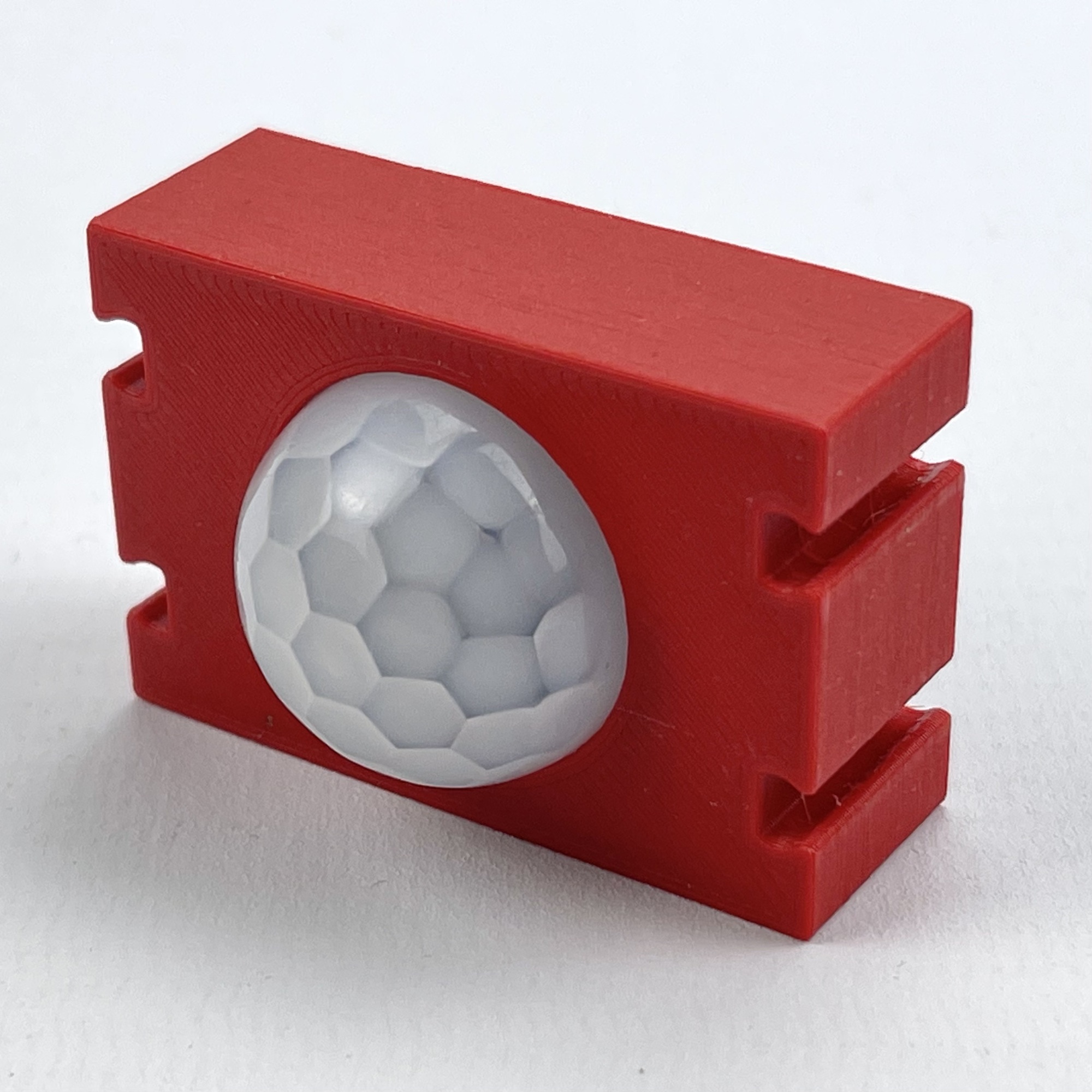
Finally, we look at the HC-SR501 Infrared PIR Motion Sensor. A passive infrared sensor (PIR sensor) is an electronic sensor that measures infrared (IR) light emitted by objects in the sensor's field of view. The sensor can detect motion in this way.
An obvious application, for example, at an exhibition is to have a model automatically start operating as soon as a potential spectator approaches. The module itself already has an adjustable timer with which the duration of operation in such a case can be set. Thus, no valuable mono-flop function, or waiting loop or counter in case of software control, needs to be spent on this.
The dimensions of this sensor differ from the above-mentioned sensors which made it necessary to develop its own housing. This was kept fairly simple in principle, which allowed the connection data and setting options to be included on a card in the open back.
The sensitivity (detection distance) and time that the output signal remains active after detection are adjustable via openings in the side of the housing with a small screwdriver. By moving a sweater you can choose between one detection pulse on repeated (within the timeout) detection of a movement, or separate pulse messages. For most applications, the "retrigger" mode seems the most obvious to me, so I initially left the sweater in place.
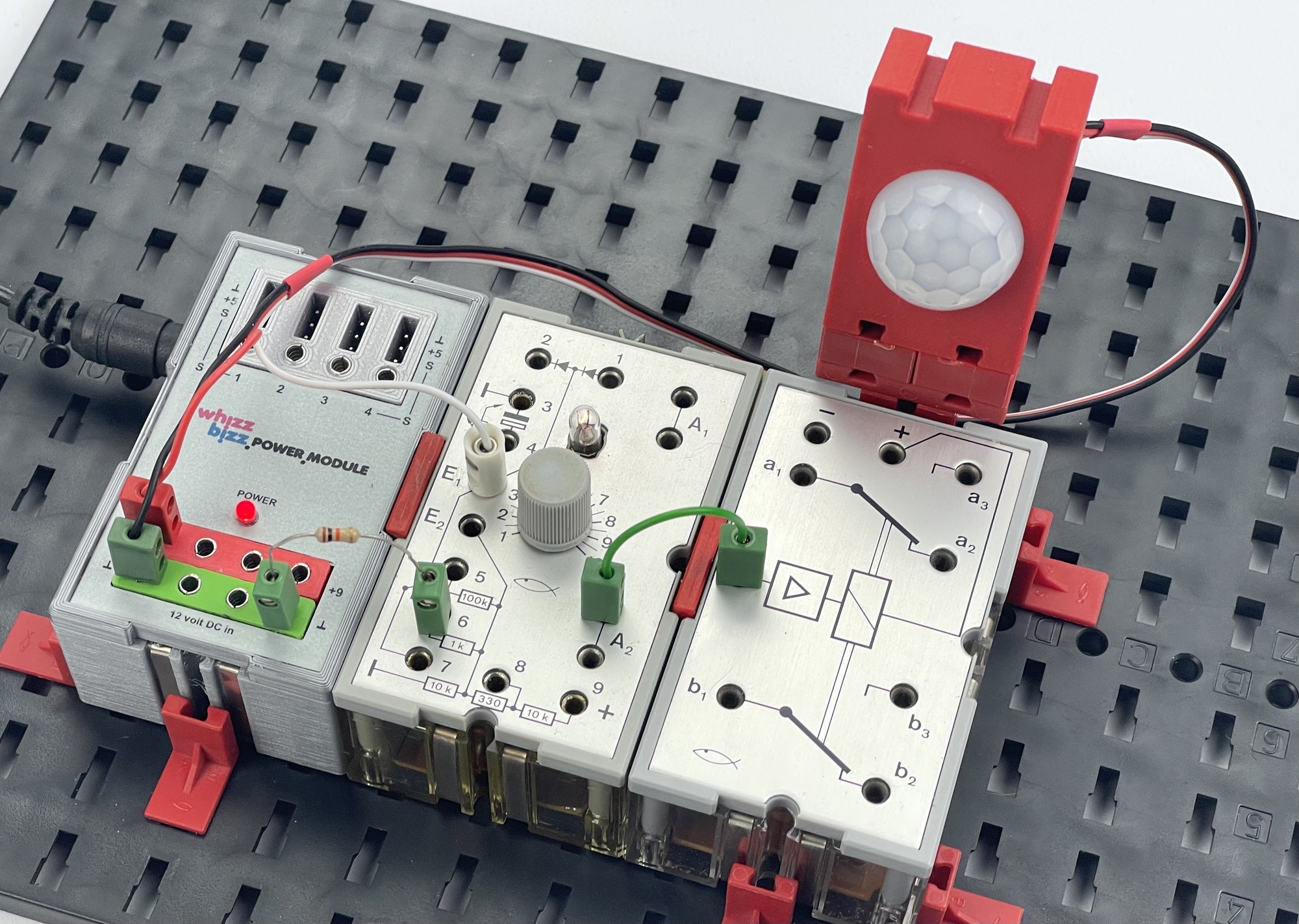
This sensor does not need to be modified to operate at 9 volts. The voltage regulator can handle a supply voltage of up to 20 volts. Internally, however, it operates at only 3.3 volts and this is therefore also the voltage level of the output signal. Switched via the fischertechnik Grundbouwstein with reduced comparator voltage (resistor of 10kΩ between socket 6 and ground) on E2, this sensor, like all other contactless switch discussed in this series, is also excellent to use in circuits built with 'Silberlingen' (see photo).
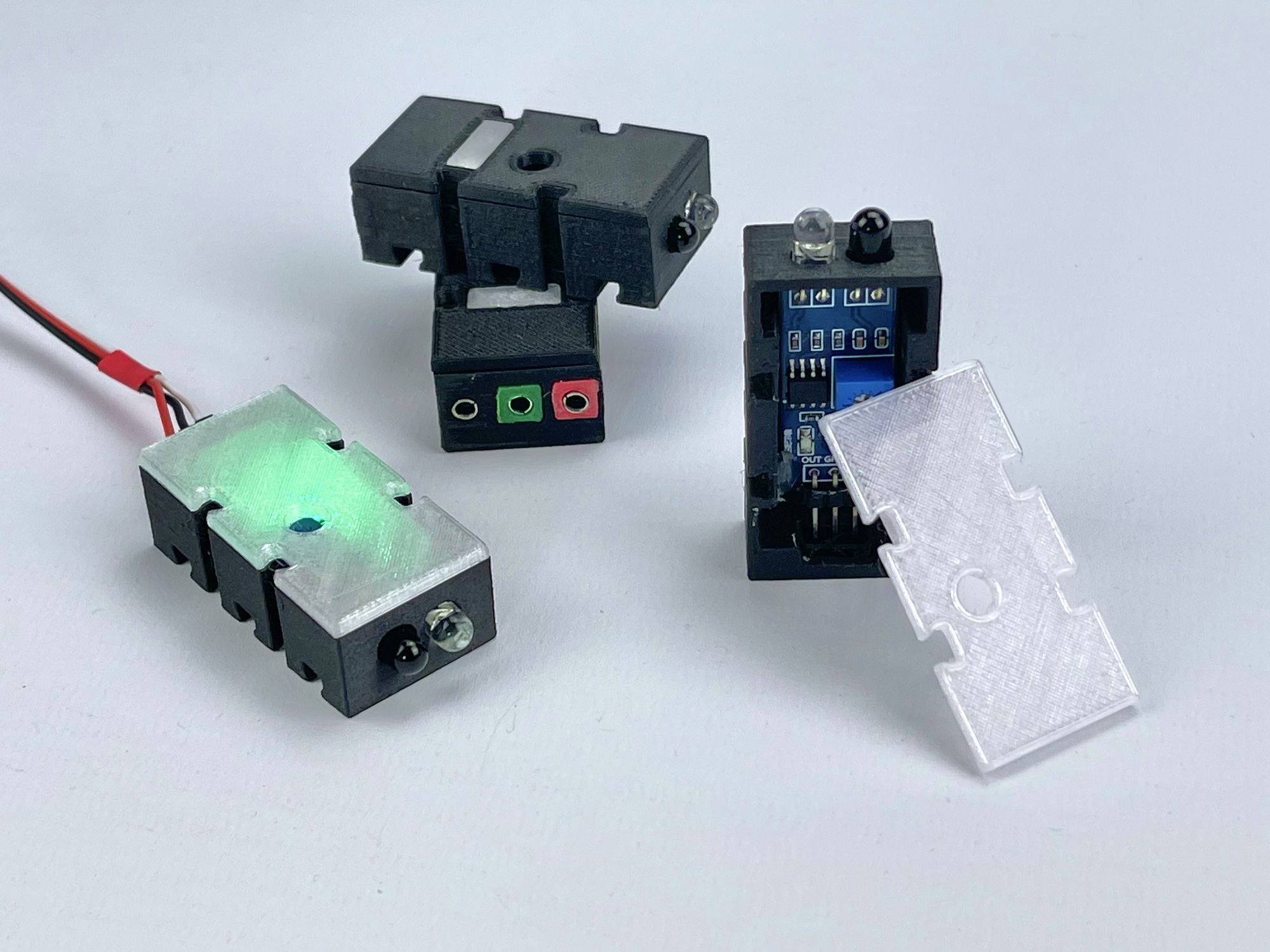
I also built some copies of the IR obstacle sensor that can be connected with the traditional fischertechnik cables with 2.5 mm plugs. Of the other sensors I simply built specimens that can be connected on the sensor side with a standard servo cable with 3-pin flat plug. However, the connection order of the three pins in this plug differs for each sensor. Fortunately, the wires in the the plug of a ready-made servo cord are easy to rearrange. The previous project page already discussed the possibilities for this.
I experimented with a closed lid with transparent diffuser and finally chose a transparent lid to make the light of the sensing LED visible. The only sensor where this could be disruptive might be the LDR module. But since the sensitivity of this module is adjustable, in practice it was not yet necessary to create a light barrier on the inside of the lid or behind the LDR to prevent incident interfering light through the lid.
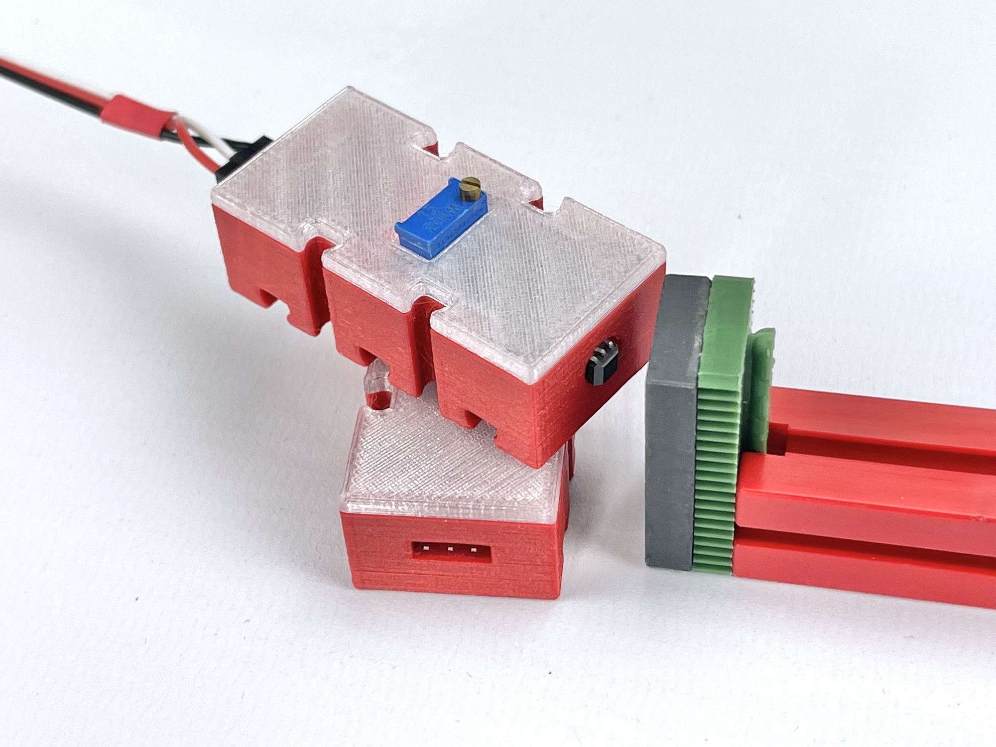
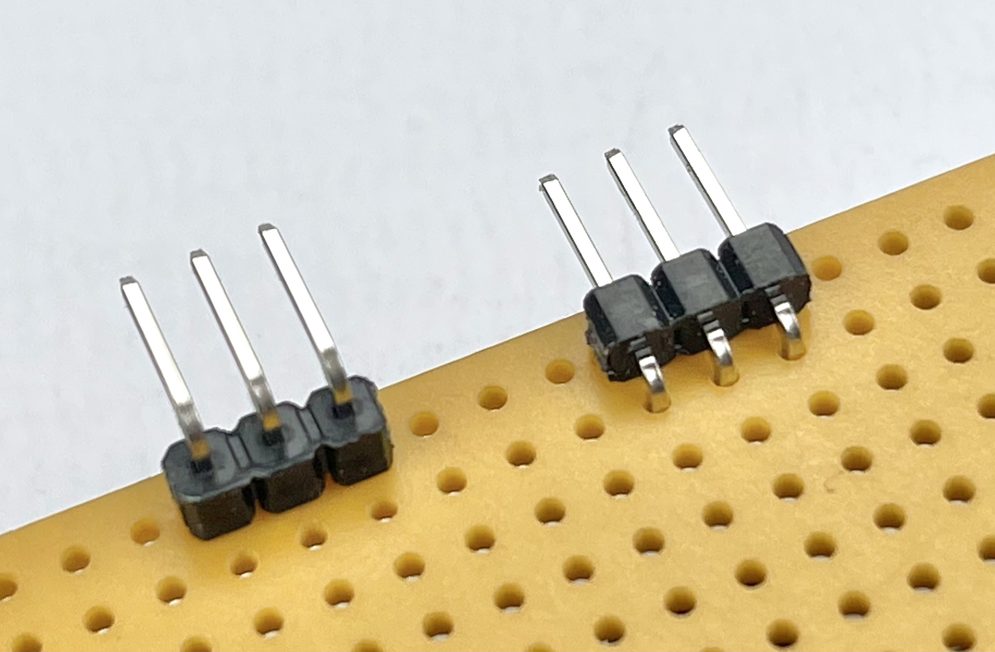
It is best if the sensors can be housed in the lowest possible housing and the opening for the connection is nicely centered. Therefore, of the sensor boards that were housed in the low housing (height 15 mm), the angled connectors had to be replaced. Indeed, most sensor modules are unfortunately supplied with straight or angled 3-pin connectors that protruded high above the sensor board, such as the connector on the left in the photo. I removed these and replaced them with the lower so-called 'Reverse bending' connectors to save installation height in the housing (horizontal connector on the right). The possibility of hot-air soldering helps here, although it is also possible to cut away the black plastic first and then desolder the individual pins with a normal soldering iron.
All sensors discussed in this article can be powered directly at 9 volts. But also with a supply voltage of only 5 volts, for example with the voltage supplies discussed earlier, it is possible for the sensors with built-in differential amplifier (LM393) to switch even the classic fischertechnik "Silberlingen" of yesteryear for those who want to experiment with circuits built with these tangible electronics modules.
The IR obstacle sensor, LDR sensor and Hall-Effect sensor are ideally suited as end or pass sensors in factory simulations or elevator models. A great advantage is that, if working with Silberlingen or electronics modules, no additional differential amplifiers such as the Grundbouwstein for the conventional light barrier are needed.
The PIR sensor seems quite suitable for having a model controlled by human or animal movements. A TXT controller obviously has no problem detecting the relatively low signal voltage of this module. But to use it as a control signal for the 'Silberlingen' a Grundbouwstein is needed. A possible wiring diagram for this was already discussed in the previous section.