
The logic AND and OR gates of digital electronics can be regarded as the tangible pioneers of Boolean algebra. After all, hardware programming on printed circuit boards with connections forms the basis of what can nowadays increasingly be solved in software.
I took a step back and played around with the logic functions of these gates using my favorite construction material. And it also turns out that mechanical equivalents of these gates can be used to demonstrate that the functionality of the AND and OR function is mathematically interchangeable.
Logic gates are the foundation of digital electronics. They have one or more inputs and an output whose logic signal level is determined by the function of the gate. The logic functions 'AND', 'OR' and the negation or 'NOT' function (the logical opposite of the input signal) form the basic functions of the so-called Boolean algebra. Because every conceivable more complex logic function can be realized first mechanically, later electro-mechanically and finally electronically (and perhaps in the near future even faster, namely in an optical way) from a combination of several of these three basic functions, relays and later vacuum tubes were developed. used to realize these basic logic functions with electronics.
The schematically shown OR gate on the right has two outputs: the normal OR and the inverted OR, which carries exactly the opposite signal at all times.
The OR function in this case describes "I can drive to work if I have a car or a bicycle". In the table on the right, all possibilities and outcomes are put in a so-called truth table. The opposite output of the input signals A and B and output OR are also included. The dash above indicates that the signal is complementary, or inverted. The table with the input and output possibilities is shown in the so-called 'truth table'.
| A | B | A | B | OR | OR |
|---|---|---|---|---|---|
| 0 | 0 | 1 | 1 | 0 | 1 |
| 0 | 1 | 1 | 0 | 1 | 0 |
| 1 | 0 | 0 | 1 | 1 | 0 |
| 1 | 1 | 0 | 0 | 1 | 0 |
Long before this became electronically possible, mechanical constructions were already made to perform certain logical functions. As with all logic functions, the way in which we technically realize the relationship between the inputs and outputs is, in principle, independent of the ultimately realized logic function. The inner workings are trivial, as long as all possible combinations of the input signals produce an unambiguous output signal according to the 'programmed' logic function.
If you search online, you will soon find 3D-printed variants or constructions made of wood, Lego or Knex. However, a purely mechanical OR function gate can also be easily constructed with my favorite construction material, fischertechnik.
In the photo on the right a compact model OR gate built on a small building plate. With such a mechanical variant, of course, no electrical voltage levels are defined for the logic '1' and '0' values. The 'positions' of the sliders on the input side (left) determine the position of the pointer on the output side (right) of the mechanism. The operation may be difficult to fathom in a static photo, so watch the demonstration in the video.
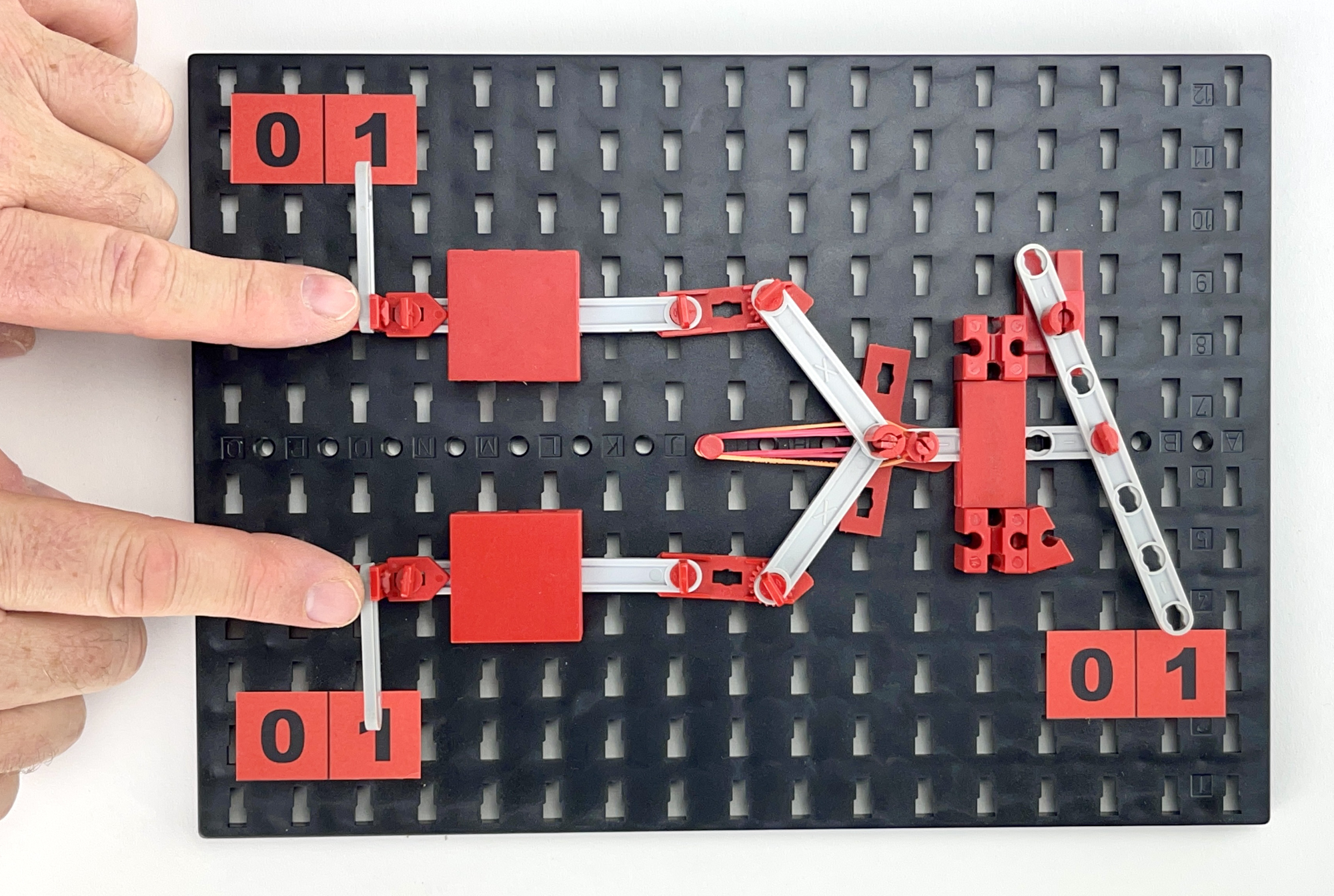
To illustrate, I enlarged the model with the moving parts in gray for better visibility. The illustrations of the larger model on the build plate show that the output OR for input values '0' or '1' of the inputs (A and B) follows the truth table of the OR function very precisely.
Another basic function in Boolean algebra is the AND function. Formulas for digital electronics often use a (thick) dot for the AND function, but in formulas the sign is the symbol ∧. The function of this gate can be written as a formula: AND = A ∧ B
The schematically shown AND gate on the right has two outputs: the normal AND and the inverted AND which carries exactly the opposite signal at any time.
The AND function in this case describes "I can choose what to drive because I have a car and a bicycle". It is possible to put all possibilities and outcomes in yet another truth table. The AND column then reads 'can choose', and the opposite or complementary result 'no choice' is then found in the AND column. On the right is the truth table with the possibilities for the input and output signals.
| A | B | A | B | AND | AND |
|---|---|---|---|---|---|
| 0 | 0 | 1 | 1 | 0 | 1 |
| 0 | 1 | 1 | 0 | 0 | 1 |
| 1 | 0 | 0 | 1 | 0 | 1 |
| 1 | 1 | 0 | 0 | 1 | 0 |
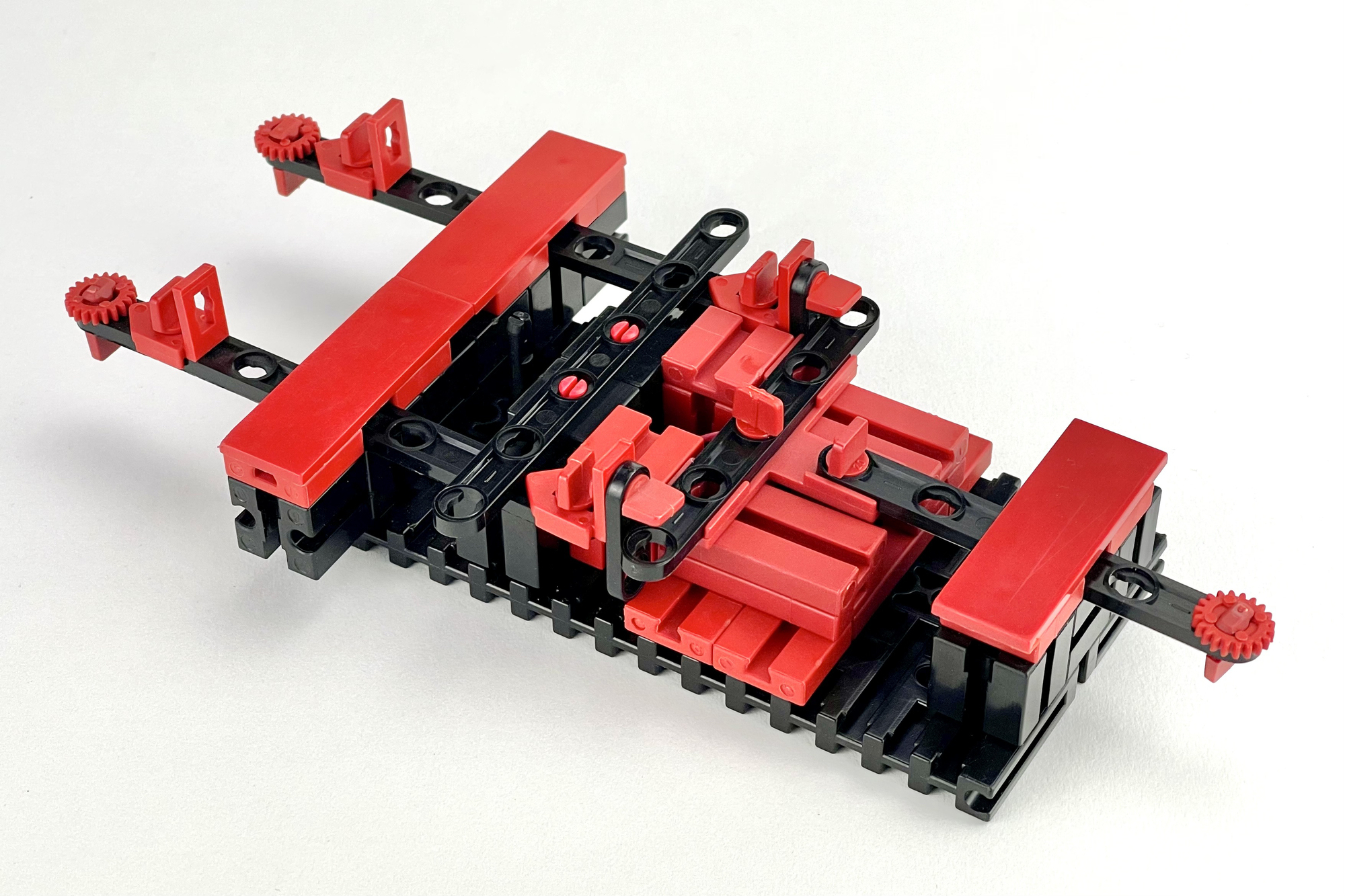
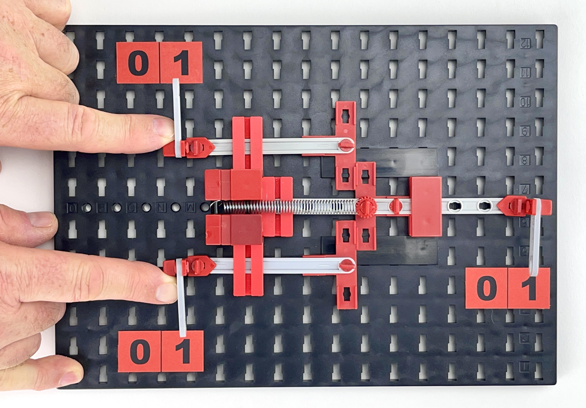
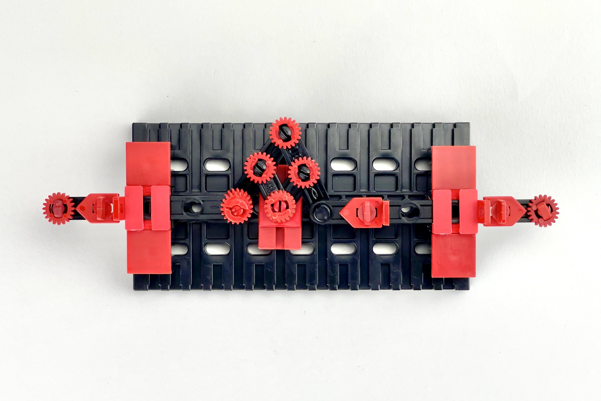
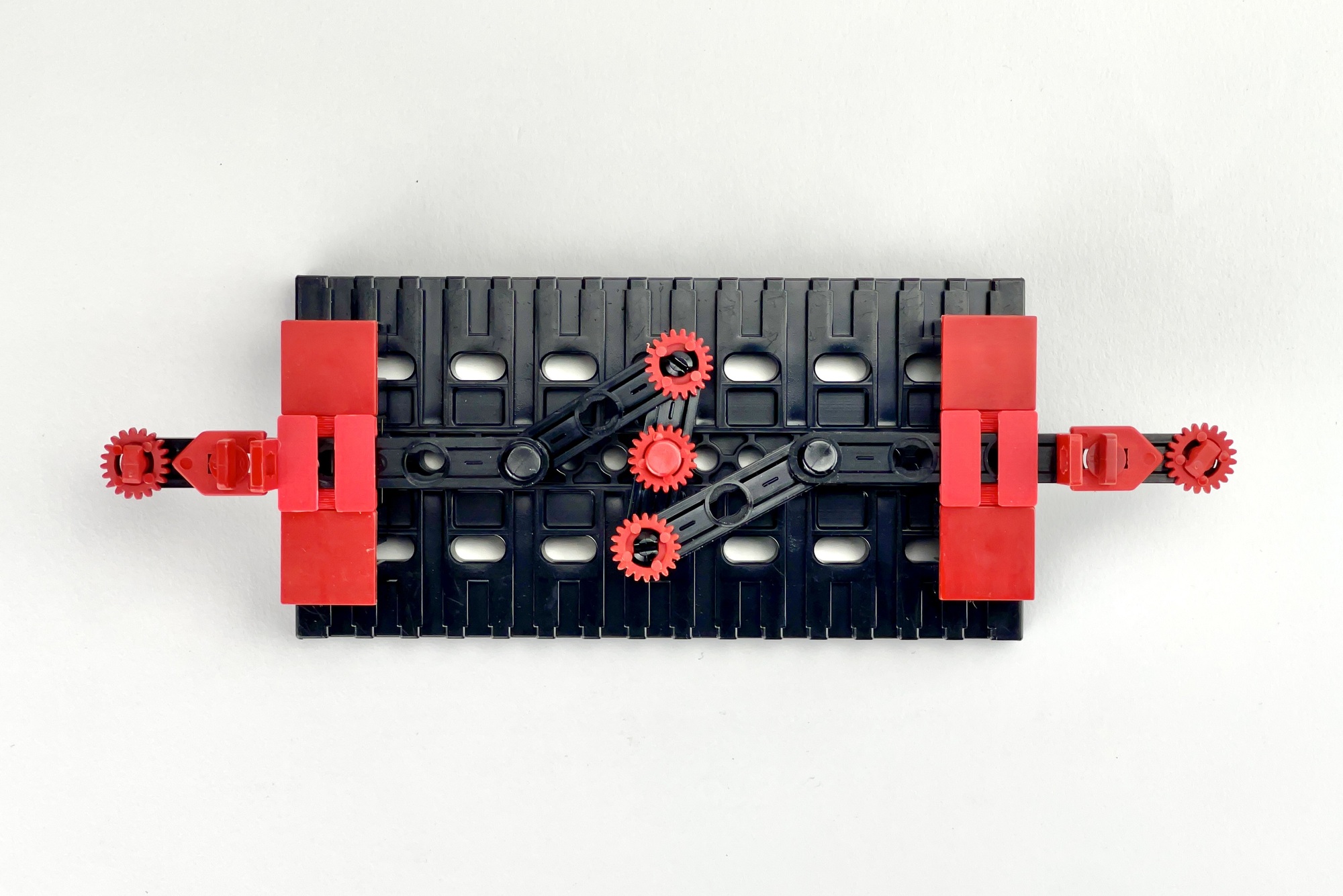
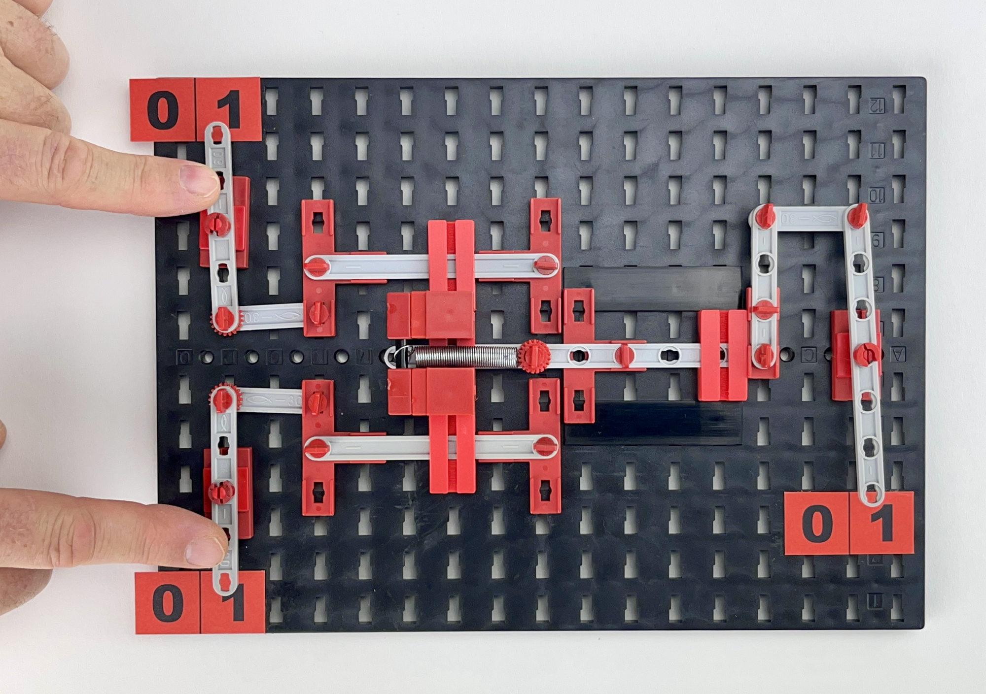
The AND function is mechanically a bit trickier to make than the OR function. The slide at the output must internally 'eliminate' the movement of one activated input signal and only move when both slides at the input are moved to '1'. This is possible with a linear movement, as here, by making the input signals move a pivoting yoke. A consequence of this is that the movement of the output signal is smaller than the movement stroke of the individual input signals. The photos show a possible functional structure of a mechanical AND function. Those who look into the matter themselves will certainly come up with other solutions.

To demonstrate the AND function, see the model on the larger build plate. The movement of the pointer of the output signal is mechanically 'amplified' with a lever. In principle, this appears to be the mechanical variant of the underlying transistor amplification stage in the early "Diode-Transistor" logic built up with semiconductors. Often, even then, a second transistor stage was included to invert the output signal (back) so that the opposite result of the function is available at the output. We will see the mechanical variant of this later on. After all, a lever can also be used mechanically to invert a movement (signal).
The last basic logic function, is the simplest of the three, and has only one input and one output. The only function of this negation, or NOT function, is to invert the input signal. The output signal is the exact opposite of the input signal at all times. If there is a logic '0' at the input, the output shows a '1', and vice versa. The output signal is complementary to the input signal.
The NOT function turns out to be relatively easy to realize mechanically. It is purely about making the end position of the output signal opposite to the movement of the input signal. On each side, the rods must therefore be pressed in or, conversely, pulled out. The photos show some examples of the construction of this function on a small building plate. The operation speaks for itself and can be better studied in the video.
In addition to the OR and AND functions, the negation, or NOT function, plays an important role as a logical basis function. It turns out that, using this NOT function, the OR and AND functions become interchangeable
The person who made these laws known was the British mathematician Augustus De Morgan. The rules named after him are also called 'De Morgan's laws', and state that every conjunction (AND function) can be expressed by a disjunction (OR function) and vice versa. They have since been widely used in mathematical proofs and software. Along with George Boole, De Morgan is considered by this definition to be the founder of formal logic.
The formulas describe that, by using the NOT function on the individual input and final logically combined output, the OR and AND basic functions become interchangeable. In other words, if the input signals of the OR function are each pre-inverted with the NOT function, the inverted output signal of the OR function will be an AND function. And vice versa, if the input signals of the AND function are each inverted beforehand with the NOT function, the inverted output signal will not behave according to the 'internal' AND function, but act as an OR function to the outside world.
De Morgan's laws can of course also be applied to the practical example of the bicycle and car above. In the function X=A ∨ B, X can in principle be explained in plain language as: "I can drive to work if I have a car OR a bicycle". Exactly the same can be expressed as: "I can't drive to work if I don't have a car AND a bike" where in the resulting formula X=A ∧ B the OR function was converted to an AND function by negating the description of the situation. Both mean the same thing and establish the same relationship between the 'input signals' and the conclusion, the 'output signal'. Only two different basic functions are used to describe the same thing.
If you scroll back, you will see that in the truth table of the OR function, the rightmost OR column for input signals A and B describes the AND function. The converse is visible in the truth table of the AND function. There, the rightmost AND column for the input signals A and B shows a logic OR function.
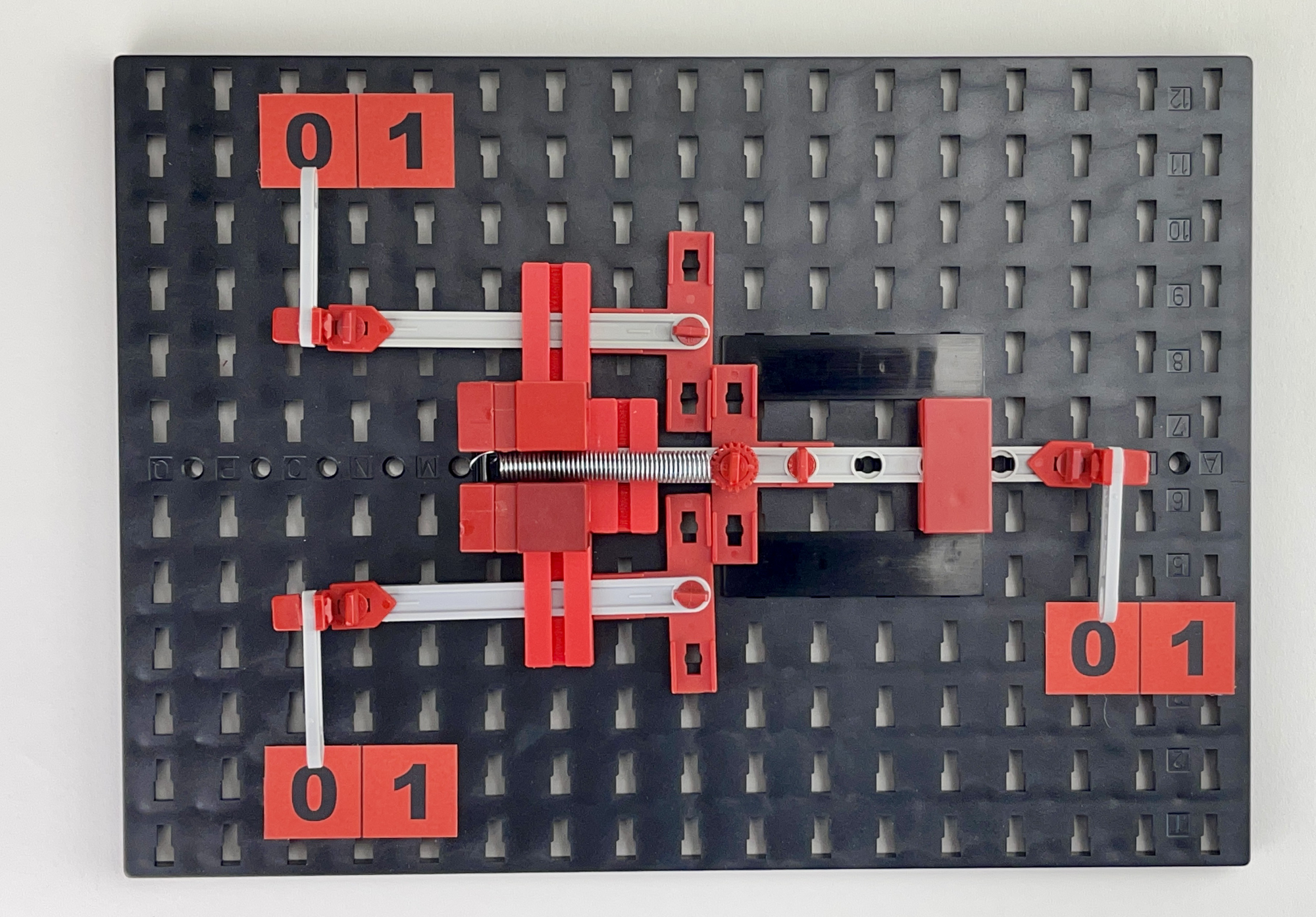
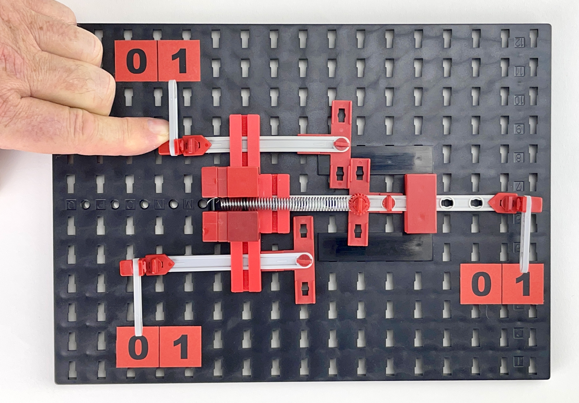
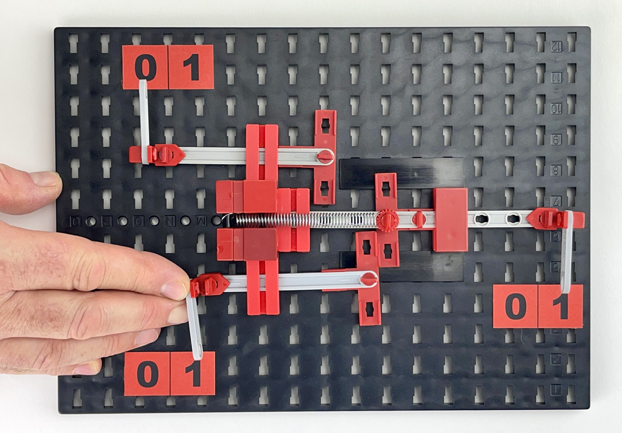
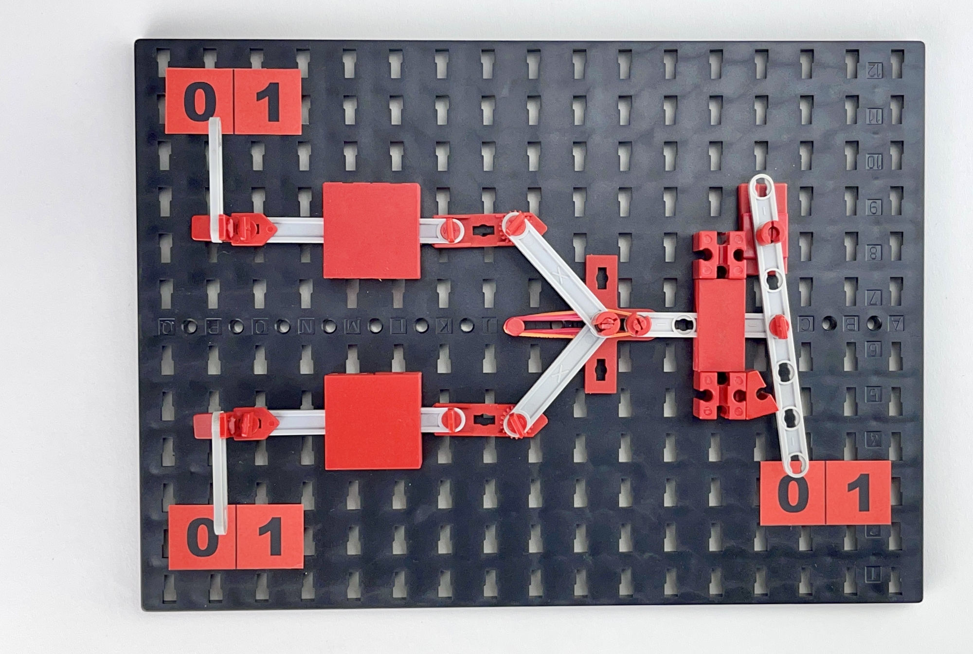
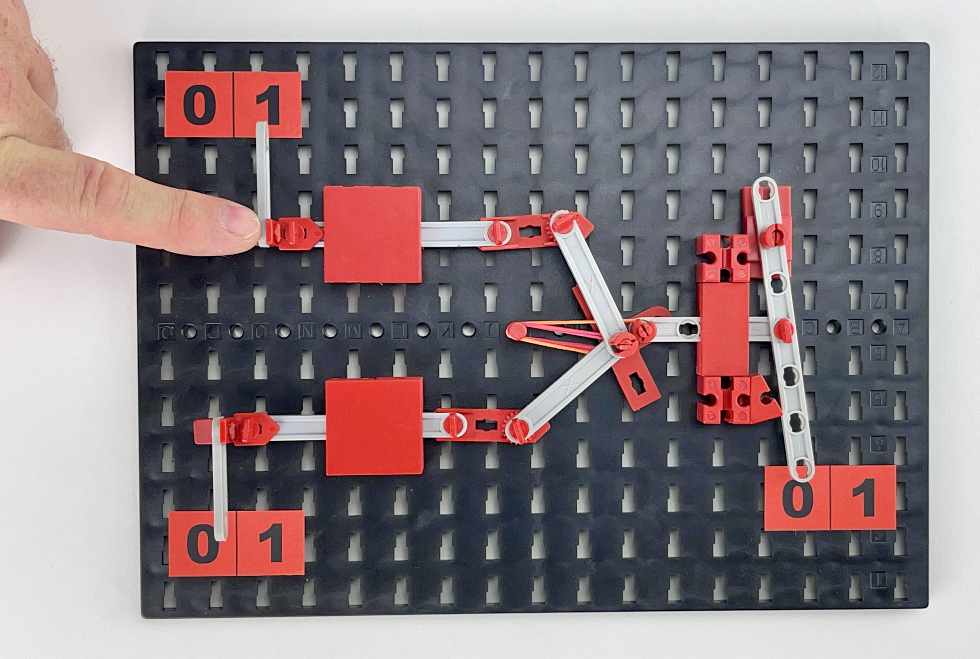
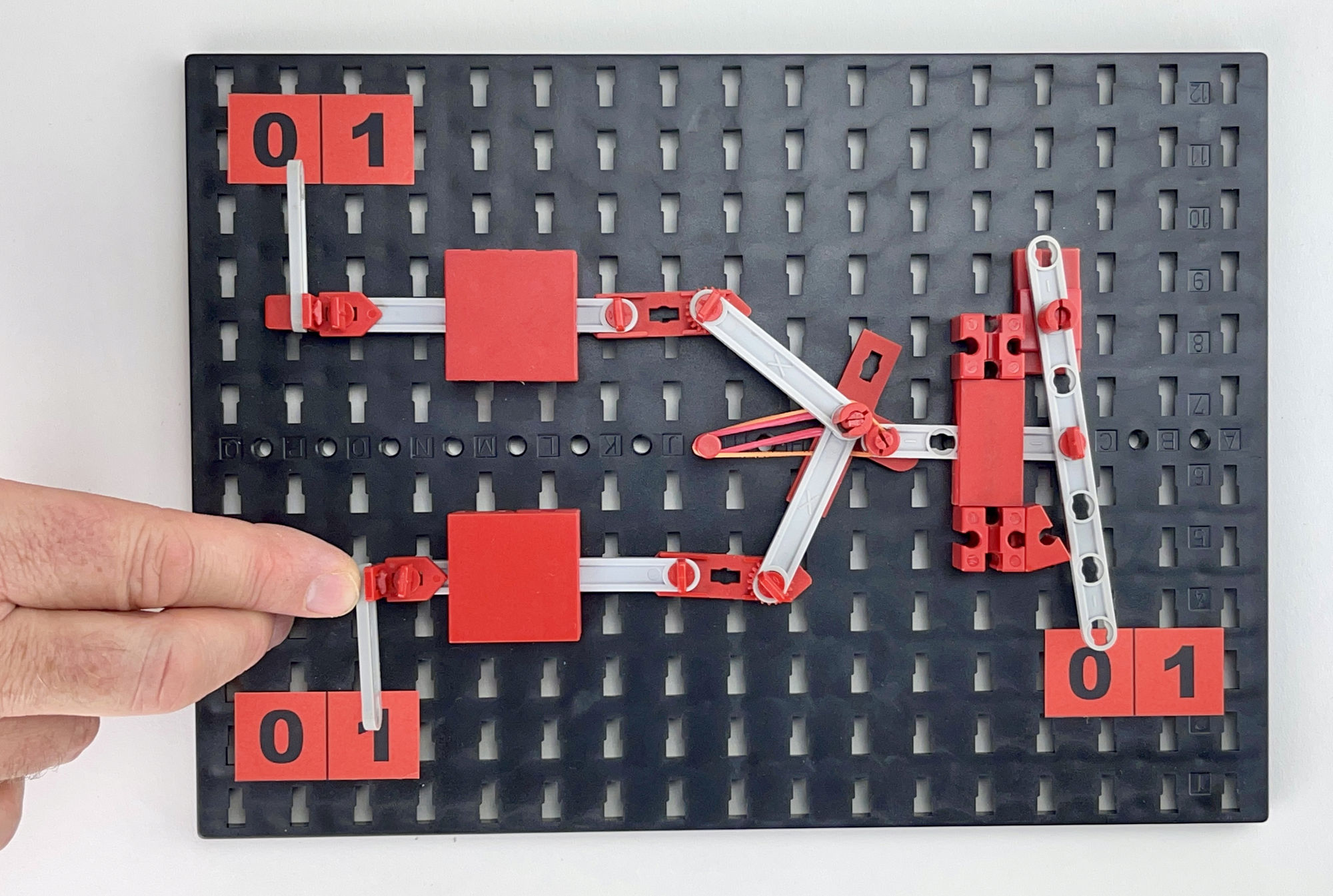
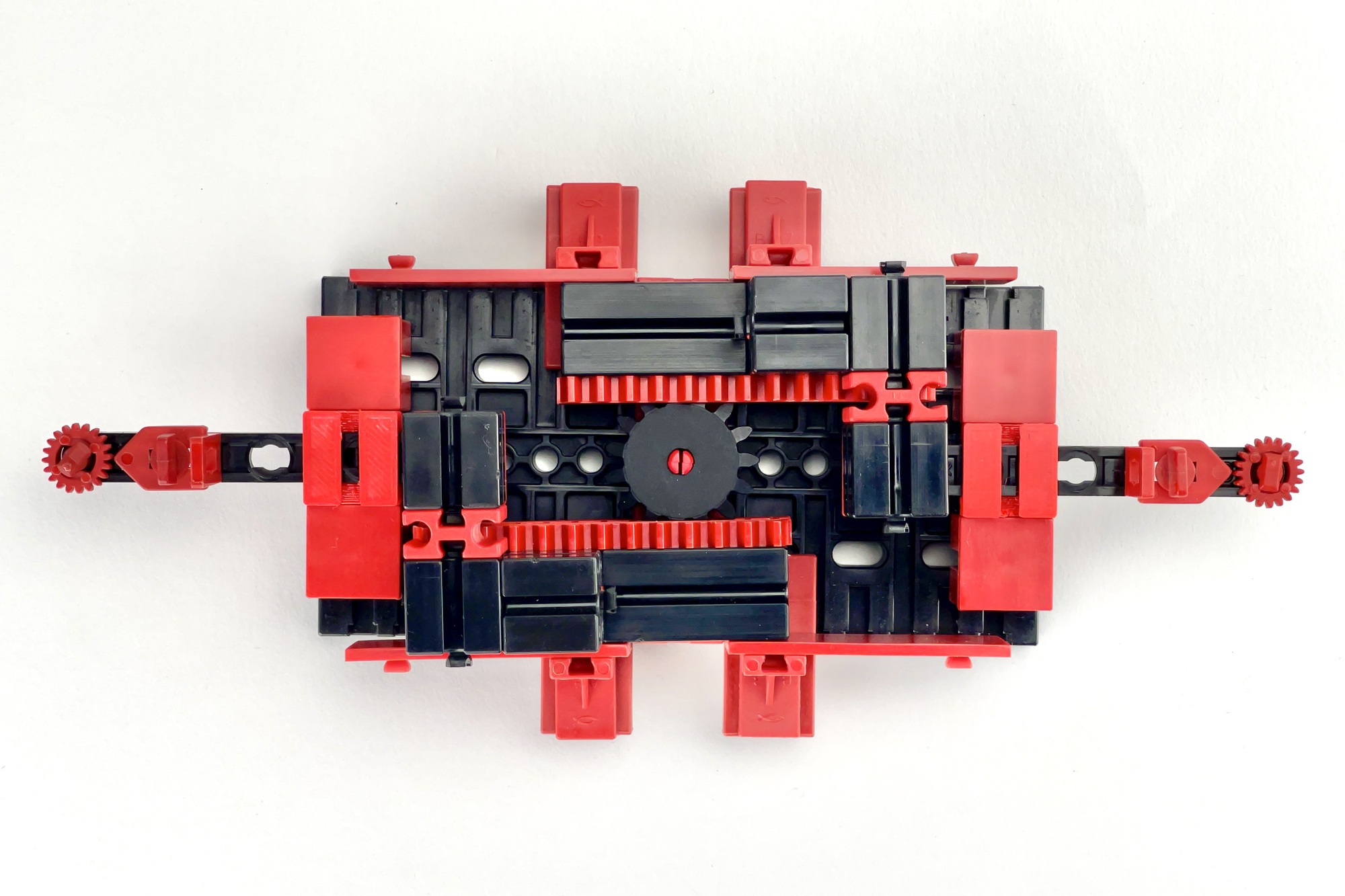
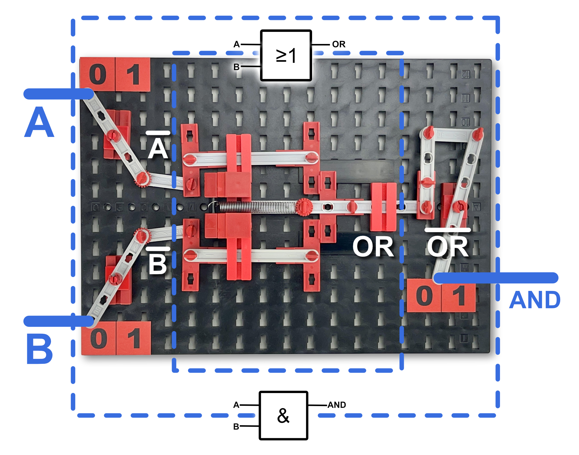
De Morgan's laws can also be visualized with a mechanical model. The basic function of the model on the right is the mechanical OR function that we saw built up above. However, with simple levers at the inputs and outputs, both the input signals and the output are inverted. As a result, this mechanical gate behaves to the outside world as an AND function.
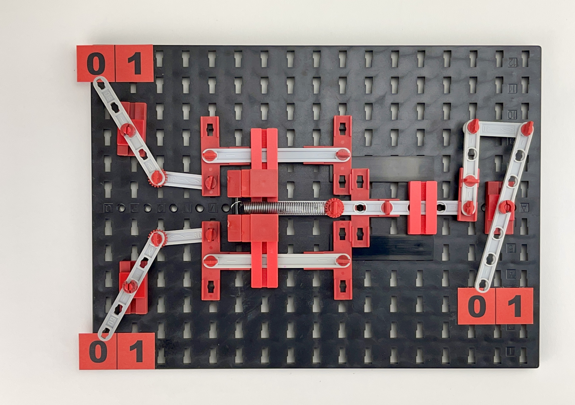
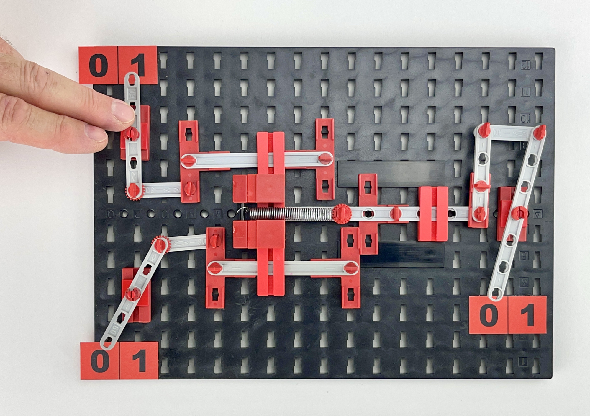
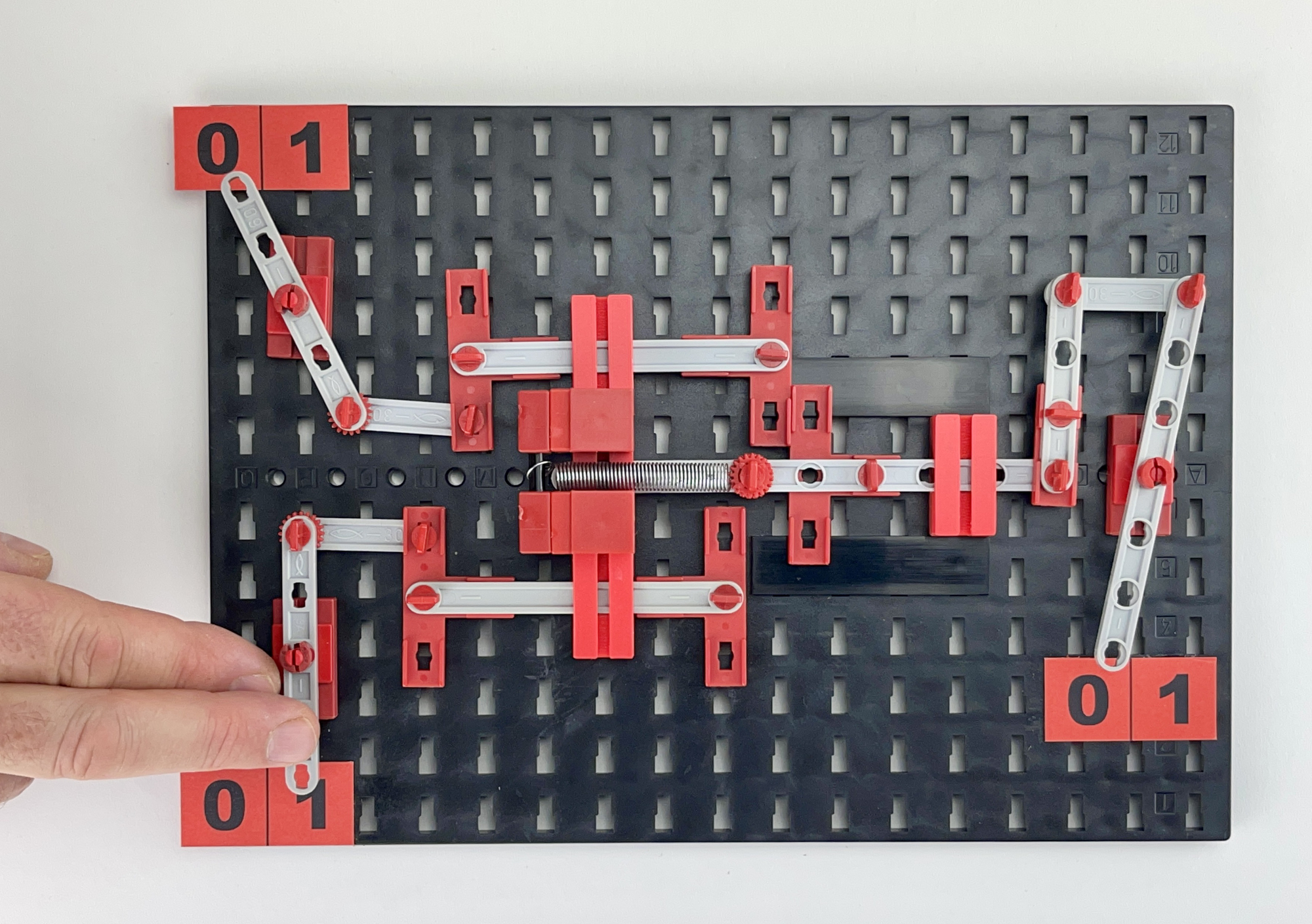
A truth table can be drawn from the four images of the various input signals of this mechanical gate below. The conclusion can only be that its output signal AND corresponds to the OR column of the truth table of the OR function, using the inverted input signals A and B, but also completely to the behavior of an AND gate described in the corresponding truth table.
So the logical OR can behave like a logical AND, and vice versa. De Morgan's laws apply as soon as we invert both the individual input signals and the resulting output signal. If a NAND or NOR gate is used as the electronic digital gate, the output signal of which has already been inverted, we even immediately have the desired input signal for subsequent gates of our logic available. In addition, NAND or NOR gates can also be used simply as simple NOT gates (inverters) if required.
The mechanical models of the logic gates provide insight into De Morgan's laws. Keep in mind, however, that many different mechanical solutions are possible for any logic function. For example, it is possible to make the functions with gears, balls that fall through courses or, for example, with ropes and weights. In my mechanical experiments, I have so far mainly investigated linear movements. Perhaps because of the visual analogy with the electronic operation of the 'Transistor-Transistor-Logik' that I knew from the later ICs. The more you think about the matter, the more parallels there are between the electronics and the mechanical models.


The linear, sliding or swiveling movement can of course be realized in many ways with fischertechnik. Not only an axis through a hole (eg in a building block) can serve as a pivot point. Pivot points can also be realized with a cardan or the various hinge stones. An opening through which a so-called 'Statika Strut' can slide is easy to make. It was just difficult to find a solution for this that stayed neatly in the 15x15 mm grid and in which the strut slid smoothly through the opening, without too much (vertical) play. Purely because it was possible, I therefore designed two custom stones for this occasion. The small one corresponds in size to fischertechnik part "Baustein 5" (15x15) no. 37237, the wider one corresponds in size to fischertechnik part "Bauplatte 5 (15x30)", no. 35049). Anyone who finds these useful may 3D-print them. If this doesn't work, take a look at the list of 3D objects I might be able to help with.
The movement of the output in these mechanical models is completely formed by the movements of the input signals. However, to build more complex functions, such as an XOR gate or Flip-Flop, several basic mechanical functions must be chained together. However, due to play and friction in the mechanical pivots, the gates shown here are not so easy to switch in succession. The force at the outputs decreases rapidly. Analogous to the solutions used for this in the electronic variants of these logic gates, a next step could be to investigate the possibilities of 'amplifying' or mechanically 'decoupling' the forces at the output. For now, I hope that my search has piqued your interest. Experiment, and let me know when you have successfully build more complex logic functions with mechanical gates! 😉