
Anyone who ever plays with electronics and circuits encounters practical problems. How do you take care of the power supply of your breadboard and how do you attach test leads and probes to the breadboard as stable as possible?
Or how do you make a neat, uninterrupted clock pulse with a push button for your digital circuit? Potentiometers, push buttons and LEDs for a clear view on your output signals quickly eat up a substantial part of your available breadboard space. In this article I describe my attempts and my most elegant solution to these problems (so far)!
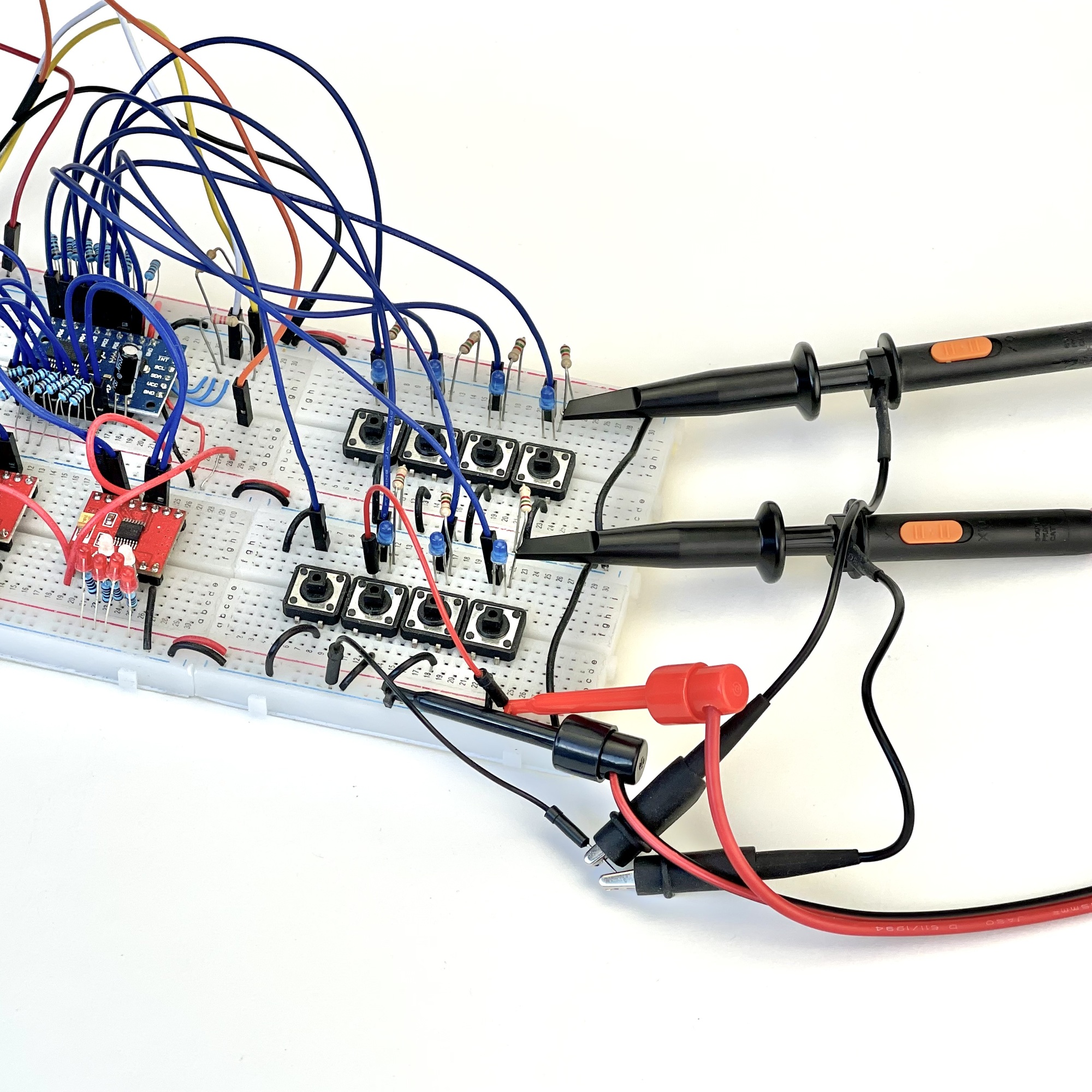
Measuring voltages or signals on a crowded experimental board is a precision job. The test probes for measuring important input or output signals are preferably mounted in such a way that you have your hands free and do not accidentally short circuit something during the reading. But test lead clips or test probes often cannot be attached directly to a pin of a component without risking a short circuit, and will therefore have to be routed to a 'measurement point' on the edges of your board. A wire bridge or the leads of an easily accessible component often offers an attachment point, but not always with sufficient strength. Sometimes it even comes down to changing the complete arrangement and moving components and wiring to make room at the edges of the experiment board to connect all these leads.
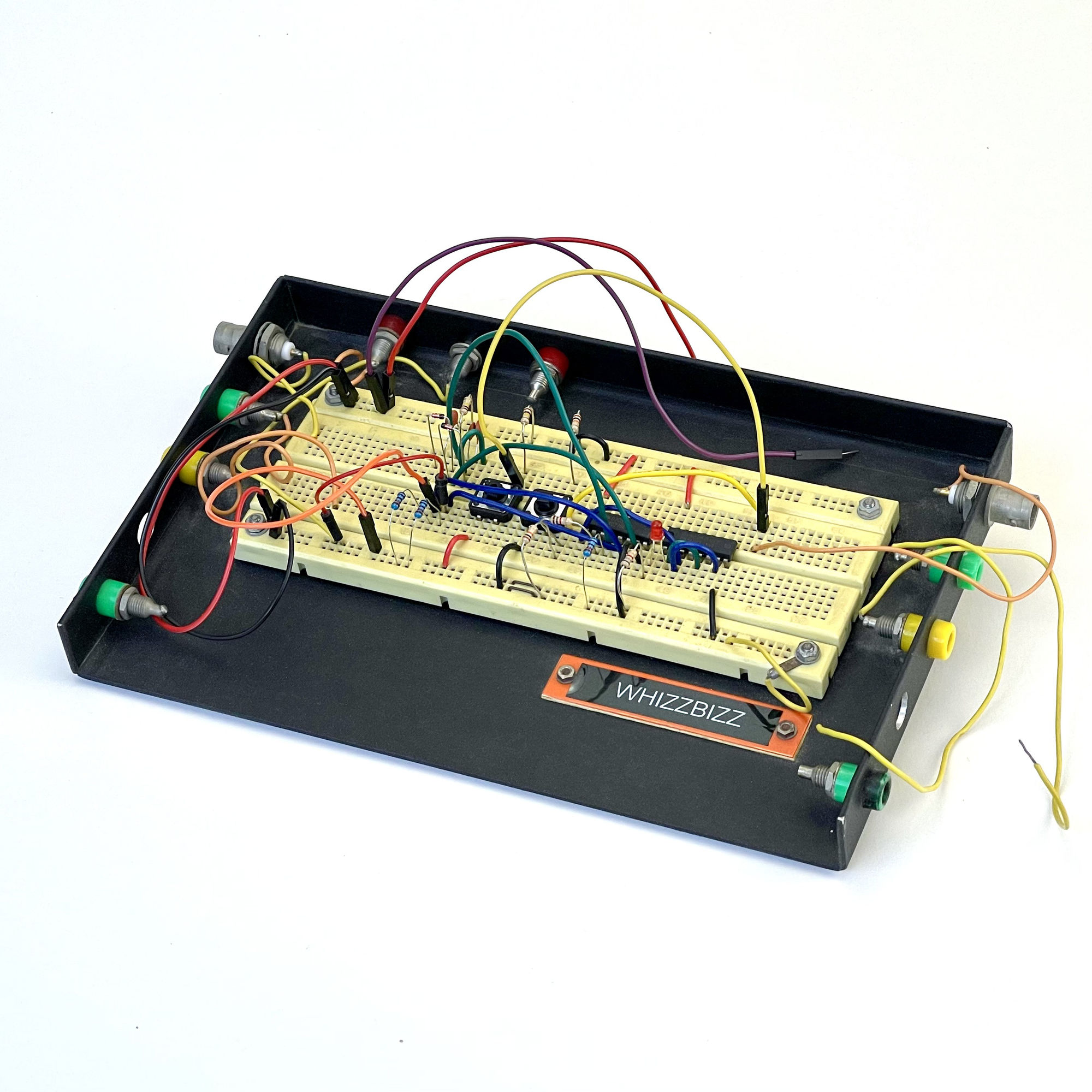
In the first year of my (electronics/computer technology) study, we made our own experiment board at school on a small aluminum plate. The sides and back were folded up about 2cm and some 4mm banana busses and a few BNC chassis parts were fitted and wired on the inside. I still use this board today, but it has a few limitations. For example, the loose threads make a messy impression and can even cause a short circuit if you do not also preventively fix the unused threads. The number of coaxial buses is also limited. And... Having the ability to insert all test leads at the back of your board would give much more stability.
An significant part of your experimenting board can be consumed by control LEDs, push buttons or potentiometers to make settings. These peripheral components are not always easy to fit into the small holes of an experiment board and often take up a relatively large amount of space. The pins of switches and potentiometers sometimes have a different pitch (than the usual 2.54mm) and are not that easy to attach and operate in a 'stable' manner.
In some electronics projects, this 'periphery' can take up quite a bit of space during the development phase of a circuit. This can partly be solved by soldering wires to push buttons and potentiometers, or by placing a set of switches on a separate experiment board, but this obviously may mess things up a bit.
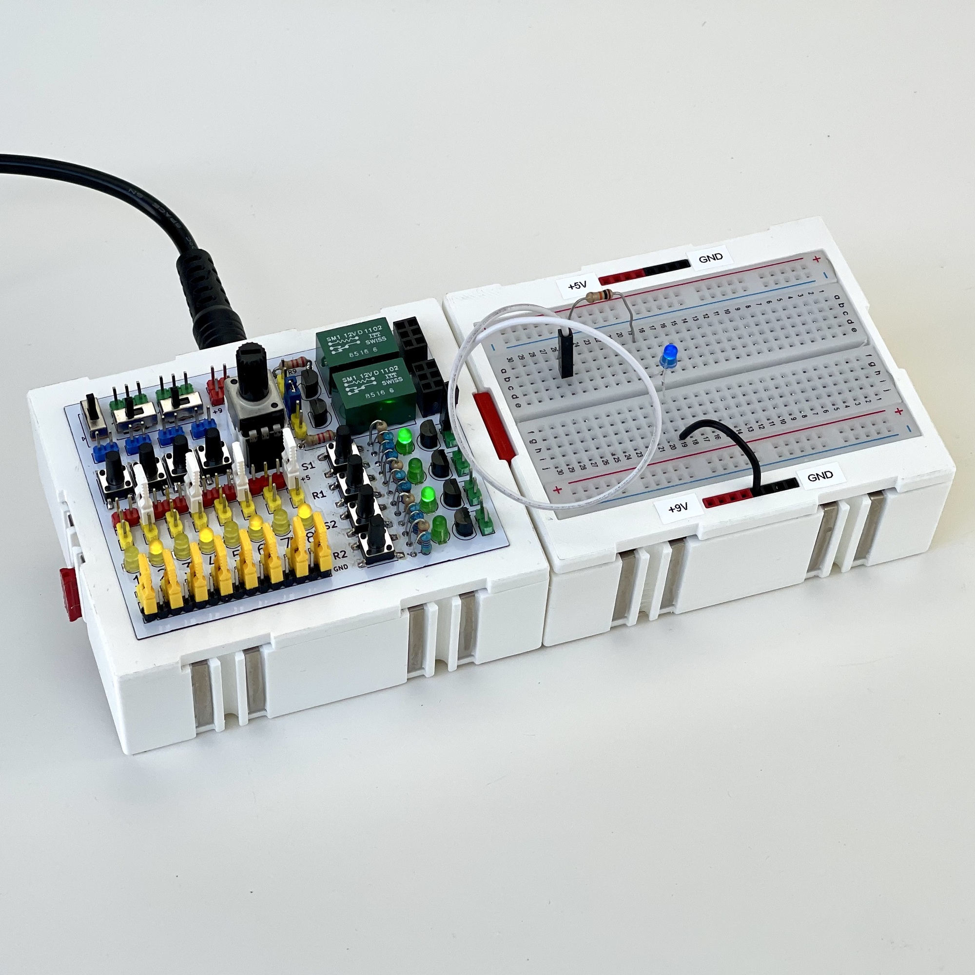
Because I wanted to be able to measure against my Zauberling and other electronics craft projects, which are housed in similar 'fischertechnik-like' housings, I decided to take a modular approach and design a box with a double 'fischertechnik Silberling' width on which a small experimental board can be mounted. The height of this housing (3cm) would make it possible to locate the various measuring connections on the back of the box. This could be a mix of coaxial BNC connectors (or even the even smaller SMA connectors) and 4mm banana plug sockets. But because the two-pole BNC connectors require relatively little space, the choice was quickly made. If the two-pole 4mm banana cords are preferred, an adapter connector offers a simple solution.
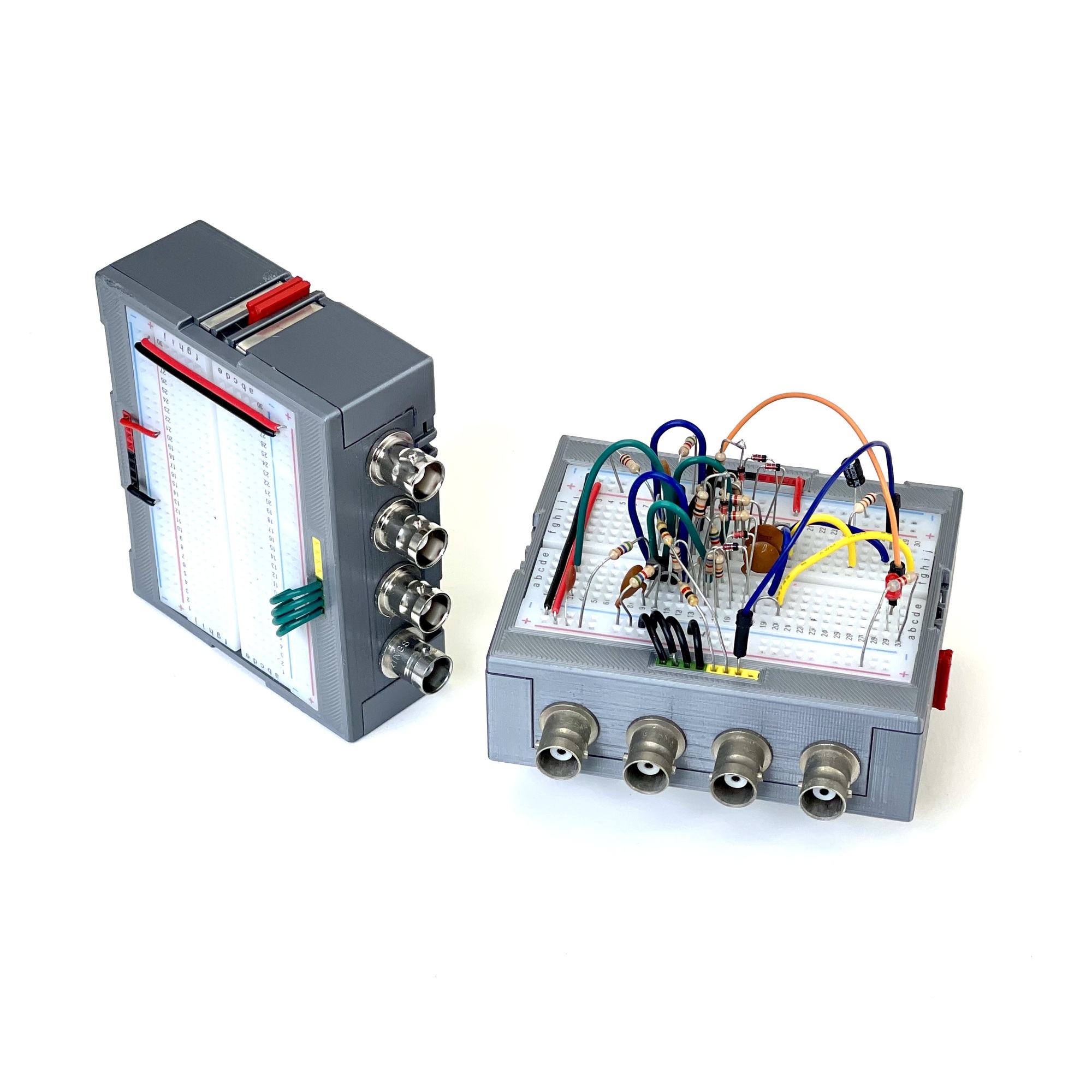
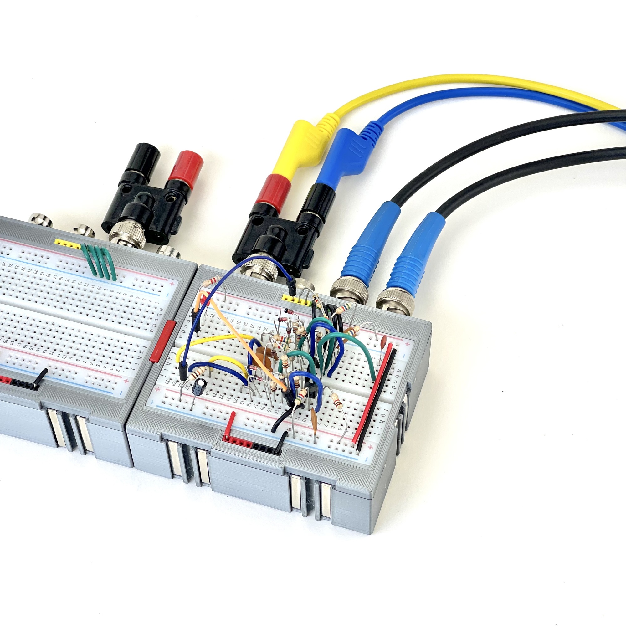
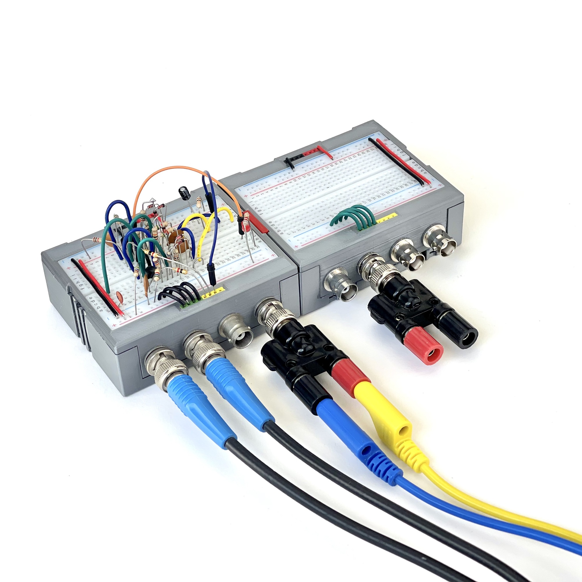
Because the BNCs do not have a common ground on a conductive chassis, but both poles are led to headers on the front of the experiment board, these measuring point connections can be used in very diverse ways. For symmetrical signals that go to the oscilloscope, the common ground can easily be applied yourself, but it is also possible to place a banana adapter and to monitor a voltage with the multimeter and 4mm test leads, for example. The wiring from the connectors to the connection points on top is neatly inside the box and the cables can be connected firmly at the back, resting on the workbench.
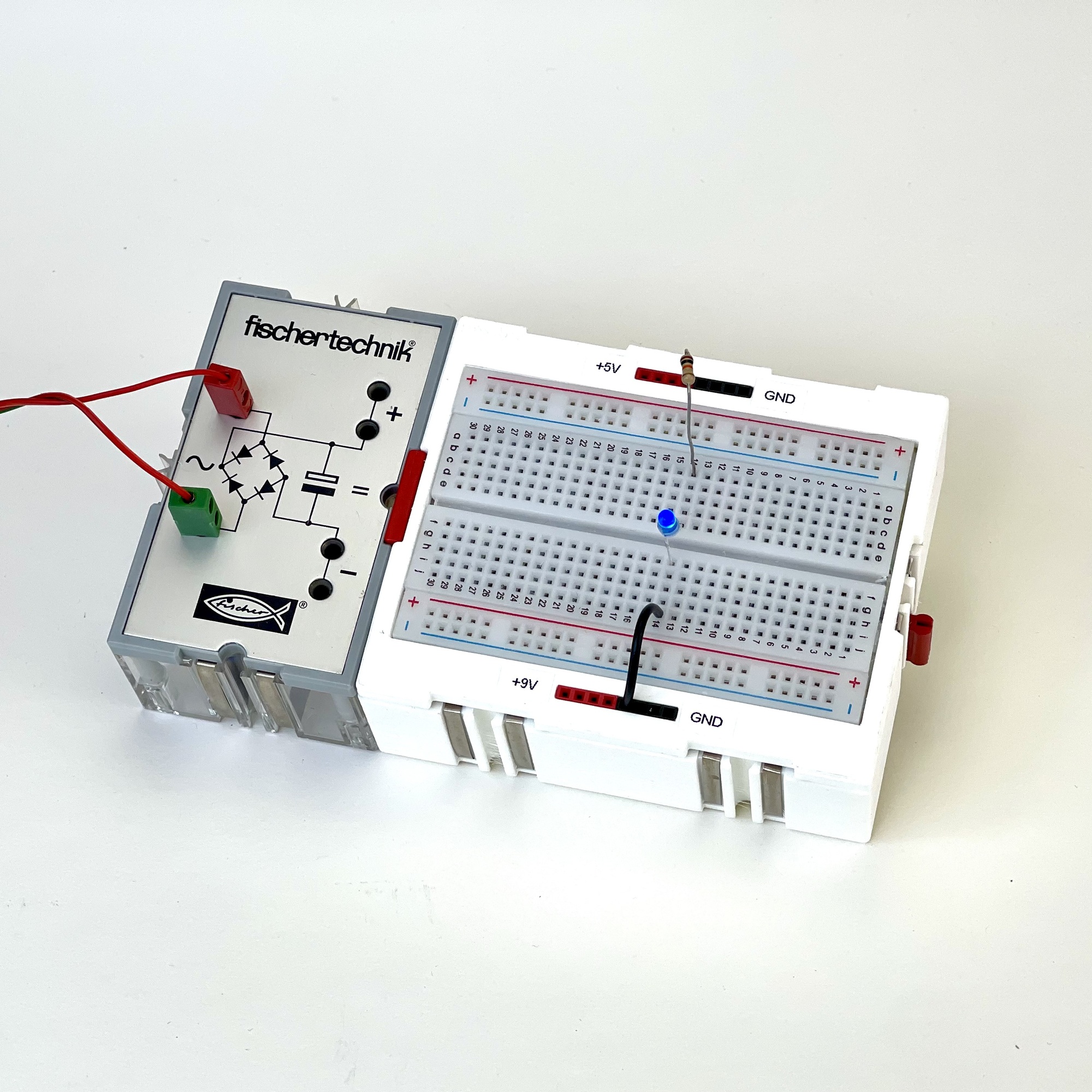
The original fischertechnik 'Silberling' housings can be slided together. Metal strips on the side of the box can be connected with a connecting clip, so that all modules connected together can easily be supplied with power. For reasons of interchangeability, I commited to the original 9 volt supply voltage when designing my own multi-power module. In addition to 9, this module also supplies 5 volts for experiments at TTL level.
However, since it seemed useful to me to also be able to use a 9 volt only power source (such as the original fischertechnik rectifier module, or a 9 volt DC adapter), I also made a variant with its own built-in 5 volt voltage regulator so that both voltages are available to be used on the breadboard. This module was made specifically for experiments with fischertechnik, which meant that the BNC measuring outputs on the back could be omitted.
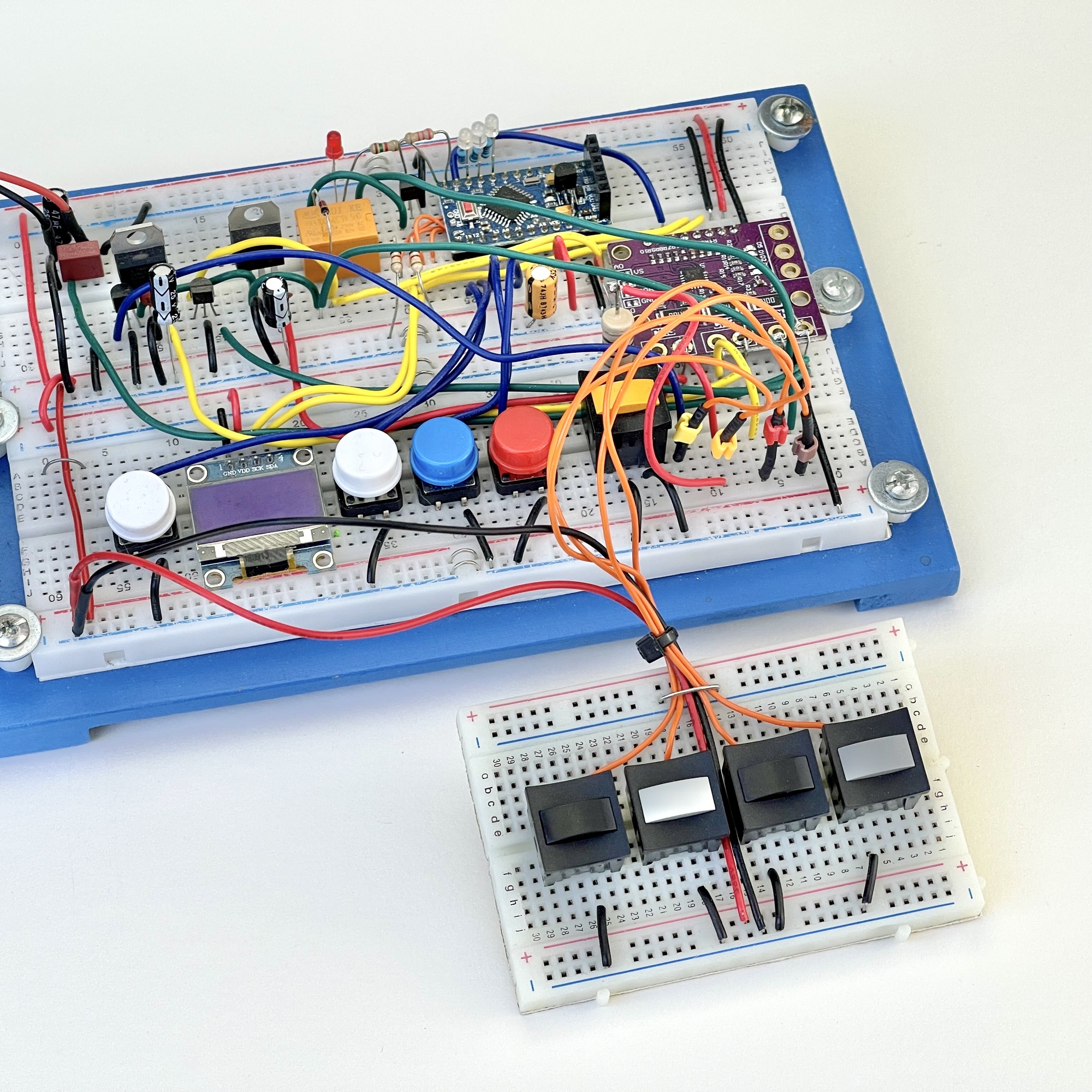
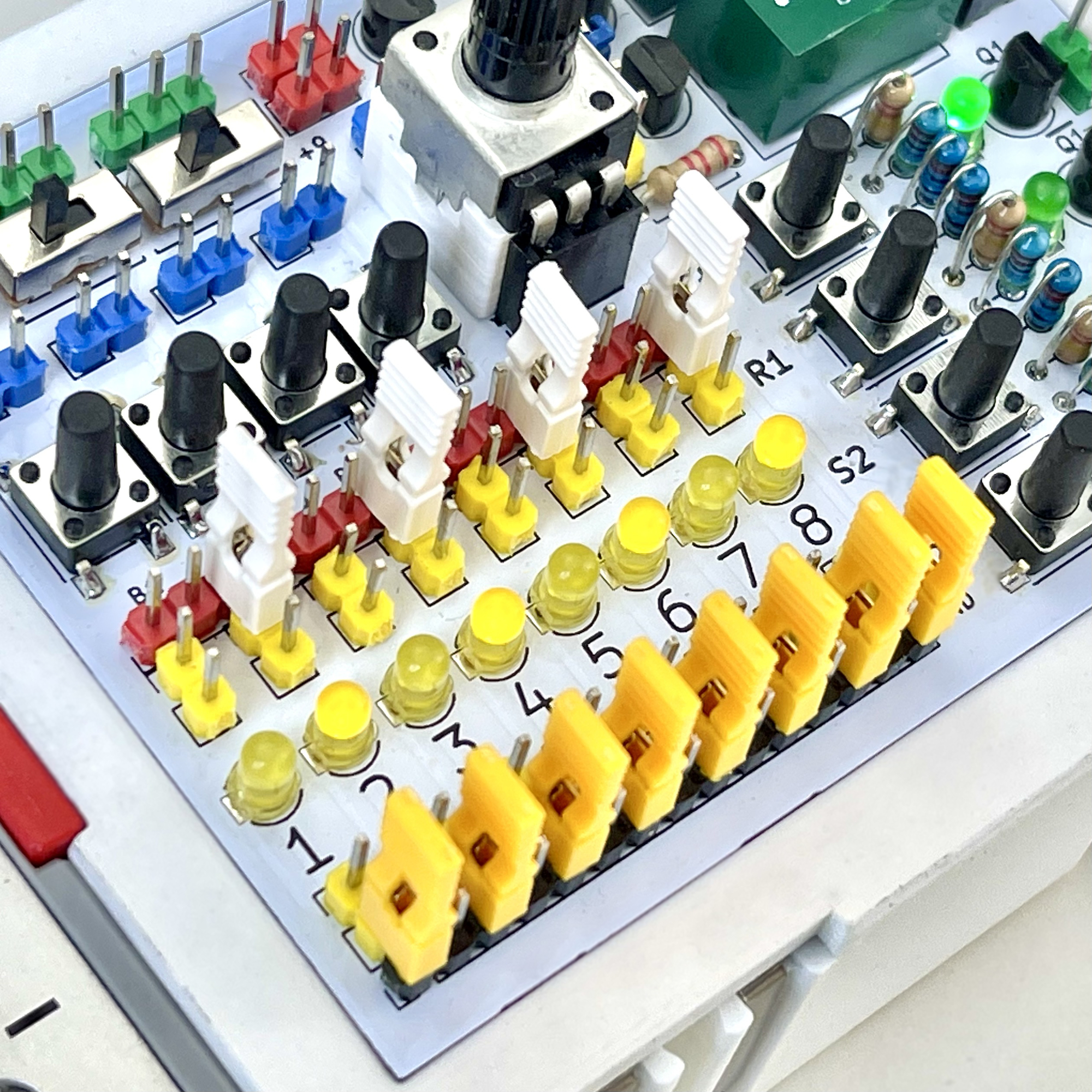
This sufficiently solved the problem of the messy, too easily detatching and loose wires. And it structured the way the power was attached. But a breadboard measuring 8.5 by 5.5 cm doesn't offer a lot of space for additional potentiometers, push buttons, LEDs, and so on. In order to meet some of the wishes, a universal PCB turned out to be for sale. 16 push buttons, four separate push buttons and a row of eight LEDs were arranged on this in a matrix. I thought it would be a useful idea if such handy auxiliary peripherals were housed in their own 'Silberling' housing so these could be chained up in any combination if the experiments required it.
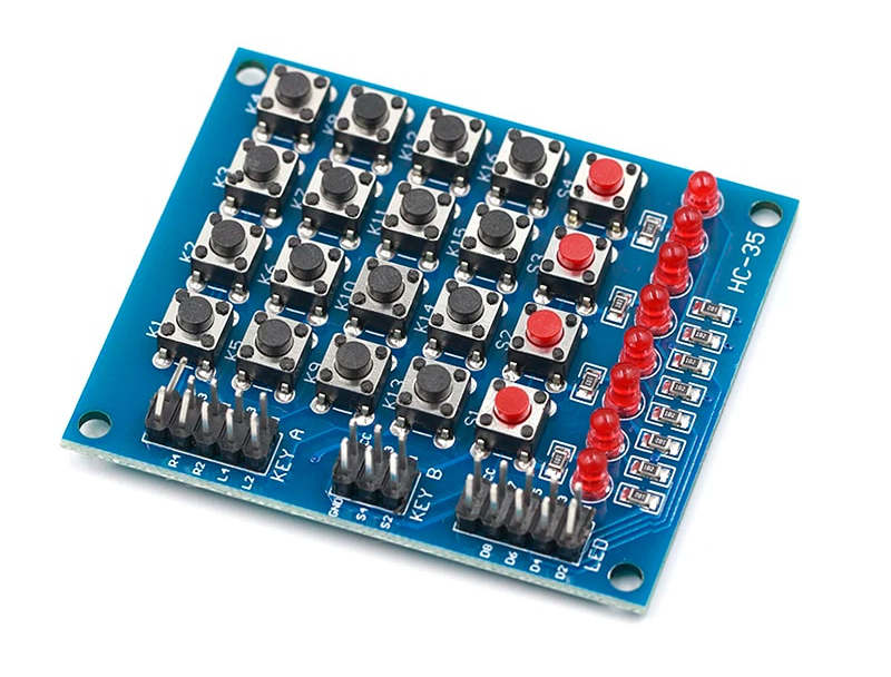
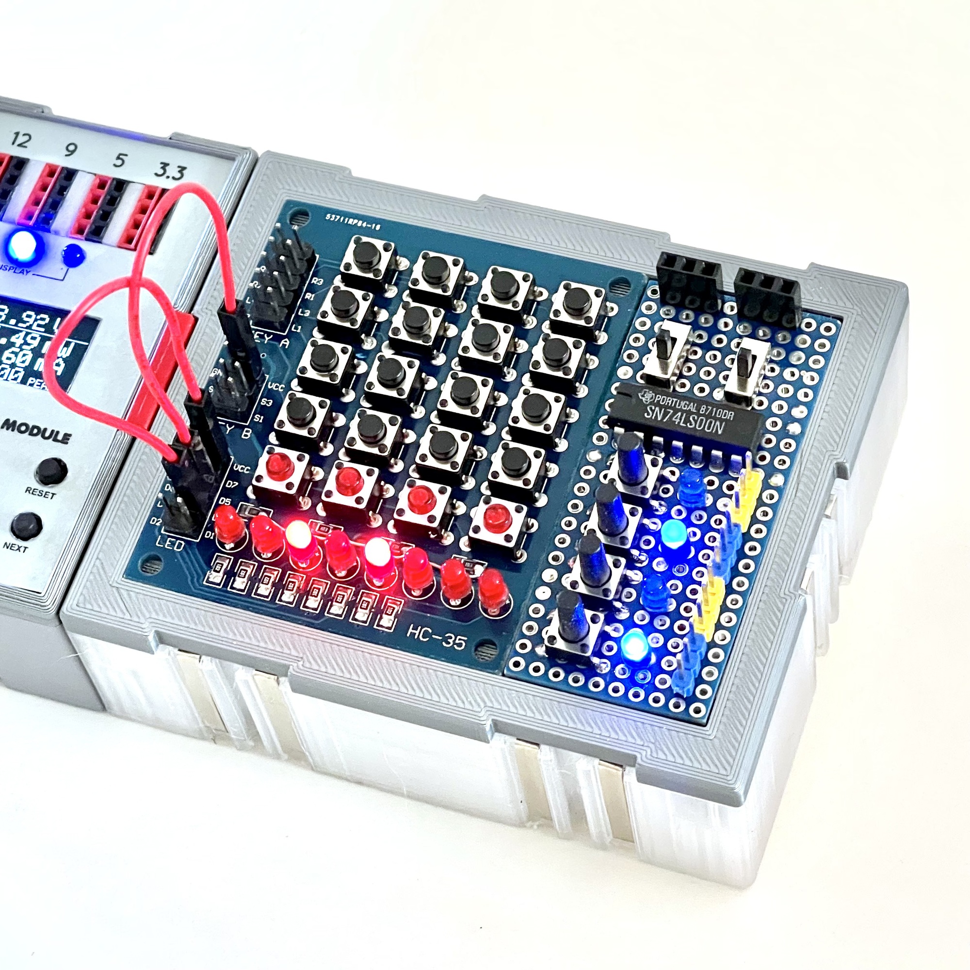
The whole matrix of 16 pushbuttons seemed quite specific to me, I would rather have had some slide switches and a small potentiometer instead. The eight LEDs turned out to have a common 'plus' (anode) and could therefore not be used at independent voltage levels. Fortunately, there was still some space left to include two slide switches and some push buttons without contact noise (to be used as a clock pulse for digital experiments) on an accompanying board.
I do not own the original, and now classic, building sets, but a slumbering wish was to be able to play with the experiments from fischertechnik's 'Elektronik Praktikum' (39410) and 'IC-Digital Praktikum' (30630) from the 1970s of the former century. This would then require a small relay on the board. Although this is a rather nostalgic and personal requirement, the DIY button board I created still lacked a decent potentiometer of course.
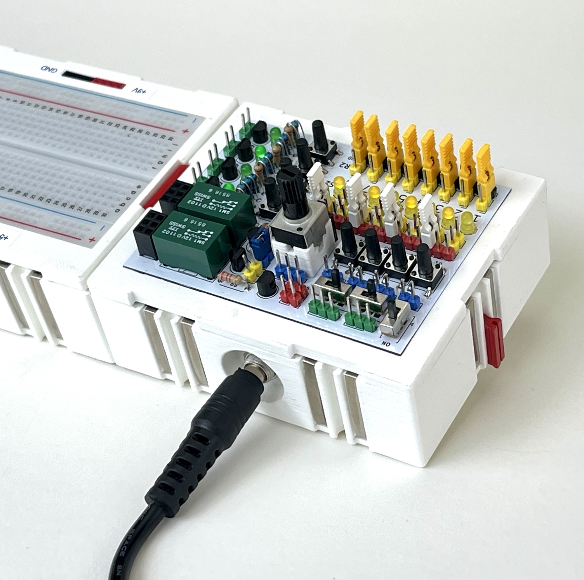
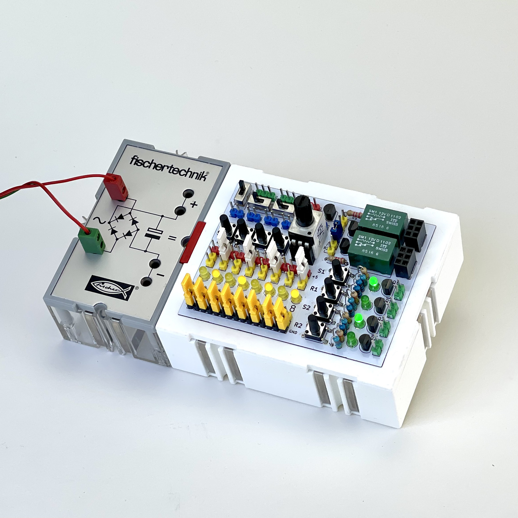
After having used the above PCB for some time, the lack of a, preferably modular exchangeable, potentiometer and a small relay started to gnaw. The fact that the LEDs could not be used independently of each other in terms of voltage levels was also impractical sometimes. So I had to make do and in the end I therefore designed my own PCB on which everything was as I had originally envisioned it. After placing the components, I built it in a 'double' Silberling housing to which a DC adapter (9 volts) can be connected directly on the back as well. From that adapter, or from the voltage offered via the strips on the sides of the case, the PCB produces an additional 5 volt supply voltage which, just like the ground and the 9 volt, is offered on a separate rail.
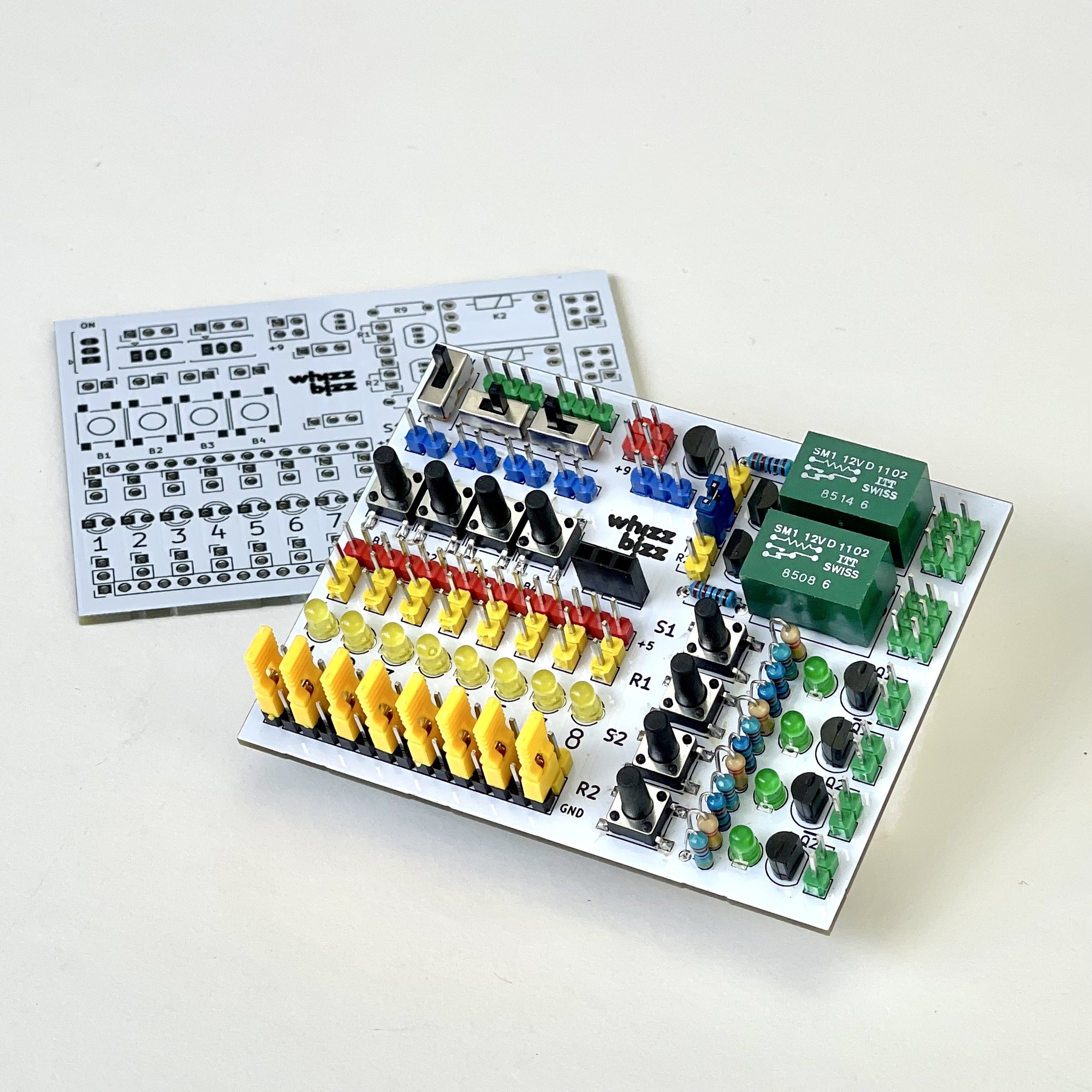
Based on the wish list, the schematic was quickly drawn up and a component arrangement quickly made. To align things nicely with the white case and the breadboard, I opted for a white silk screen finish.
The SR latch must be alternately 'Set' or 'Reset' with the 'S' and 'R' push buttons. The 'HIGH' output (TTL level, positive logic) is indicated by a lit LED. The complementary output is also always available.
This collective PCB is self-powered and offers two slide switches, four momentary pushbuttons, eight LEDs, two relays, a modular potentiometer and two aforementioned SR latches for a clear clock signal without contact noise for digital projects.
It has its own on/off switch and the LEDs (with their series resistors) can be used flexibly as readout signals because they can be switched by means of jumpers completely 'floating' or with one side to ground or to the plus 5 volts. This allows any mix of the eight LEDs on open-collector, or 'low-active', outputs to be used, as well as monitoring 'high-active' signals where the LED has to be wired to ground.
The very small green ITT relays are rather exotic. I had a whole bunch of them from the 'Usable Residual Materials Department' ('ABR' in Dutch) of AT&T/Philips in Hilversum, where I worked for years. They are relays from telephone exchanges. They are very quiet and compact relays that can nevertheless switch a maximum of 1 Ampere. I admit I was led by nostalgia when I finally decided to use them. 😀
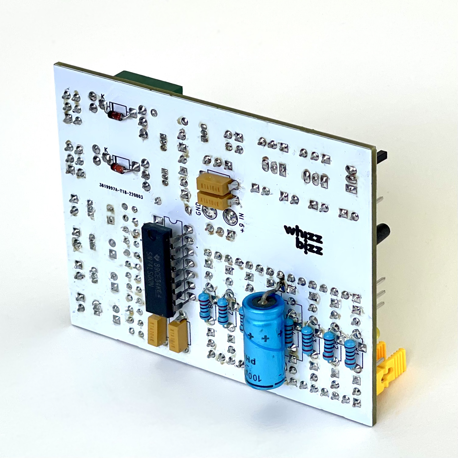
The front of the printed circuit board obviously had to be used optimally for the placement of useful switches, LEDs and push buttons. The two SR latches were constructed from the four NAND ports of a 74LS00, which is mounted on the back of the circuit board in SMD style for this reason. The series resistors for the LEDs and a few other small parts could also found a place there, nicely out of sight.
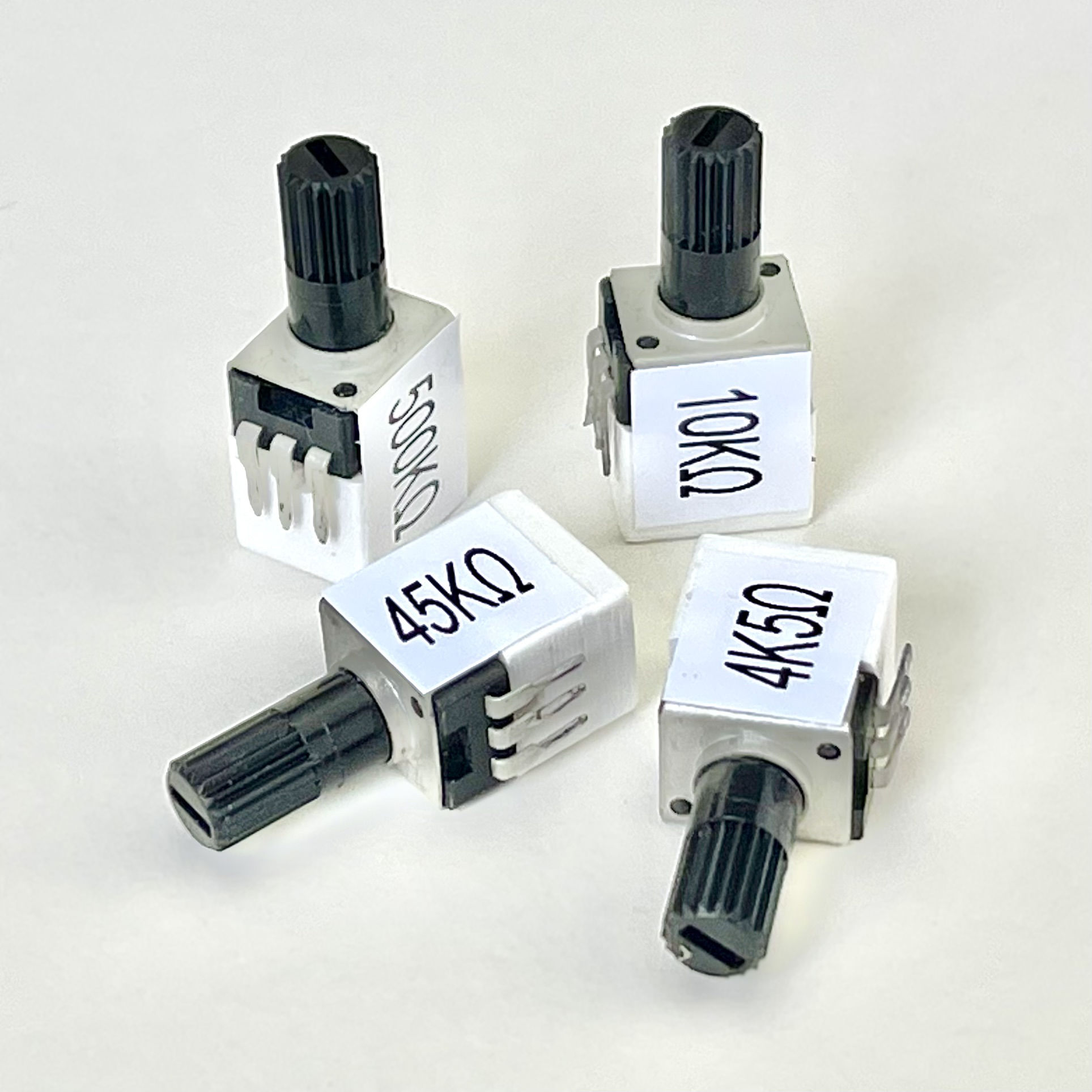
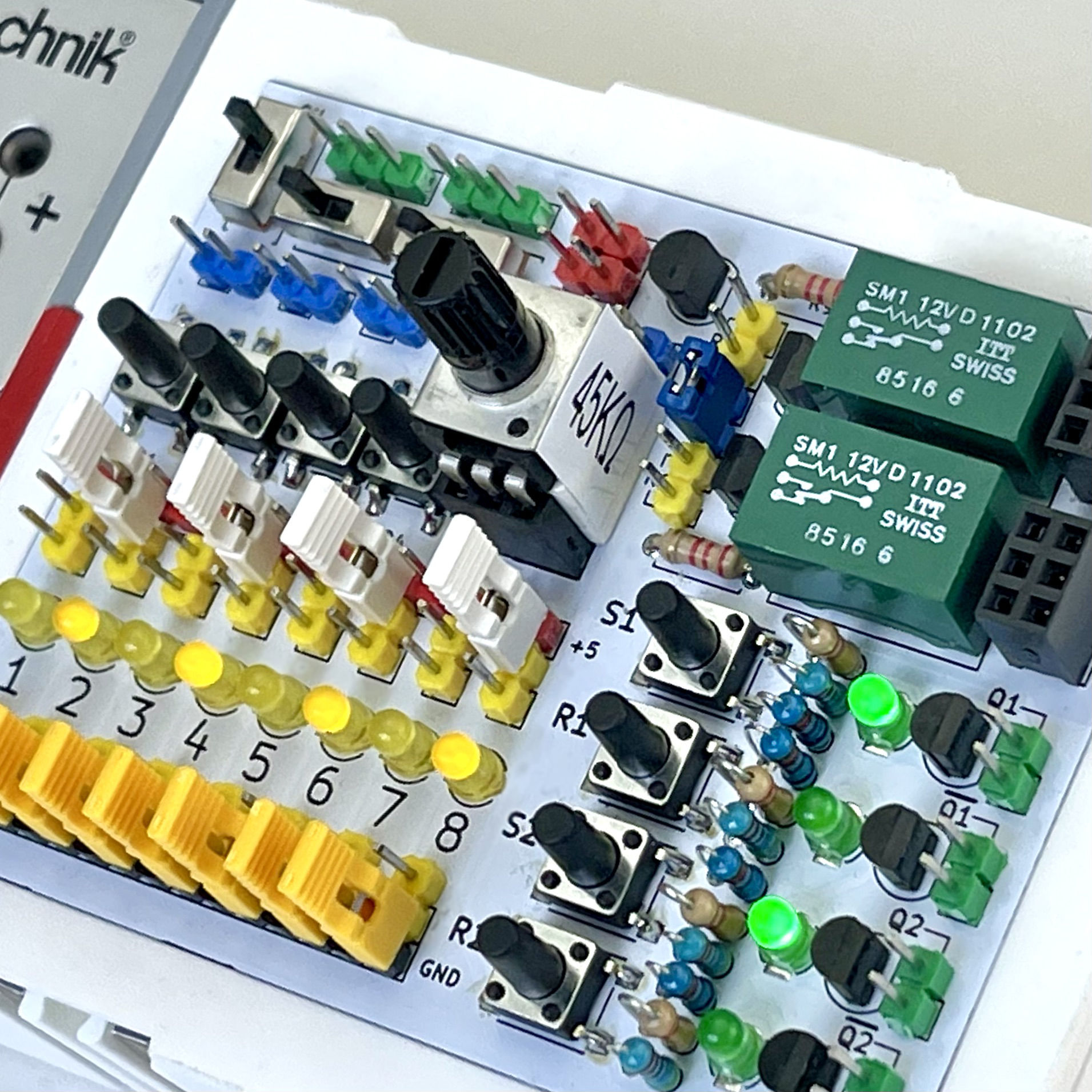
In order to be able to choose the most suitable potentiometer value for each project, potentiometers of 4K5Ω, 10KΩ, 45KΩ or 500KΩ with 3D-printed fittings can be placed on the board. Two separate relays with one changeover contact each, offer additional flexibility compared to one relay with double changeover contacts. With the blue jumper (see photo) the (amplified) signal input can be combined to a relay function with double changeover contact. In that case only one input signal needs to be connected. The board also offers extra connection pins to dispatch ground, 5 and 9 volts to the test circuit on the experiment board.
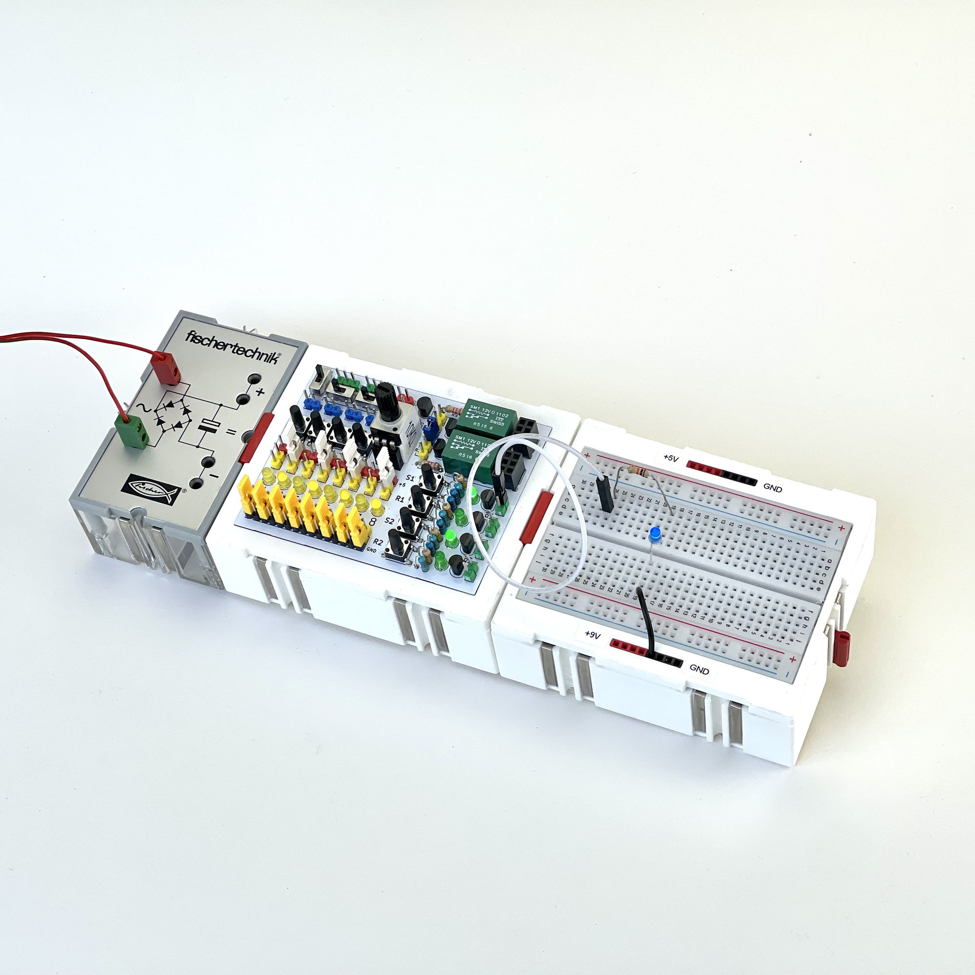
The modules discussed here have already made various electronics experiments considerably more pleasant. I've used them in various combinations. Test leads are organized, out of the way and won't come loose. The small breadboard offers enough space to build a principle circuit more often when the peripheral board is used. The interchangeable potentiometers make it easier to choose an appropriate value. The SR latches with which their 'clean' clock pulses free of contact noise will soon come in handy when experimenting with CMOS counters.
But first it's time to start working on the nostalgic desire to build that classic fischertechnik experiments! I will devote a separate article in the German engineering magazine ft:pedia for the seriously interested 'fischertechniker' to that! 🤓