
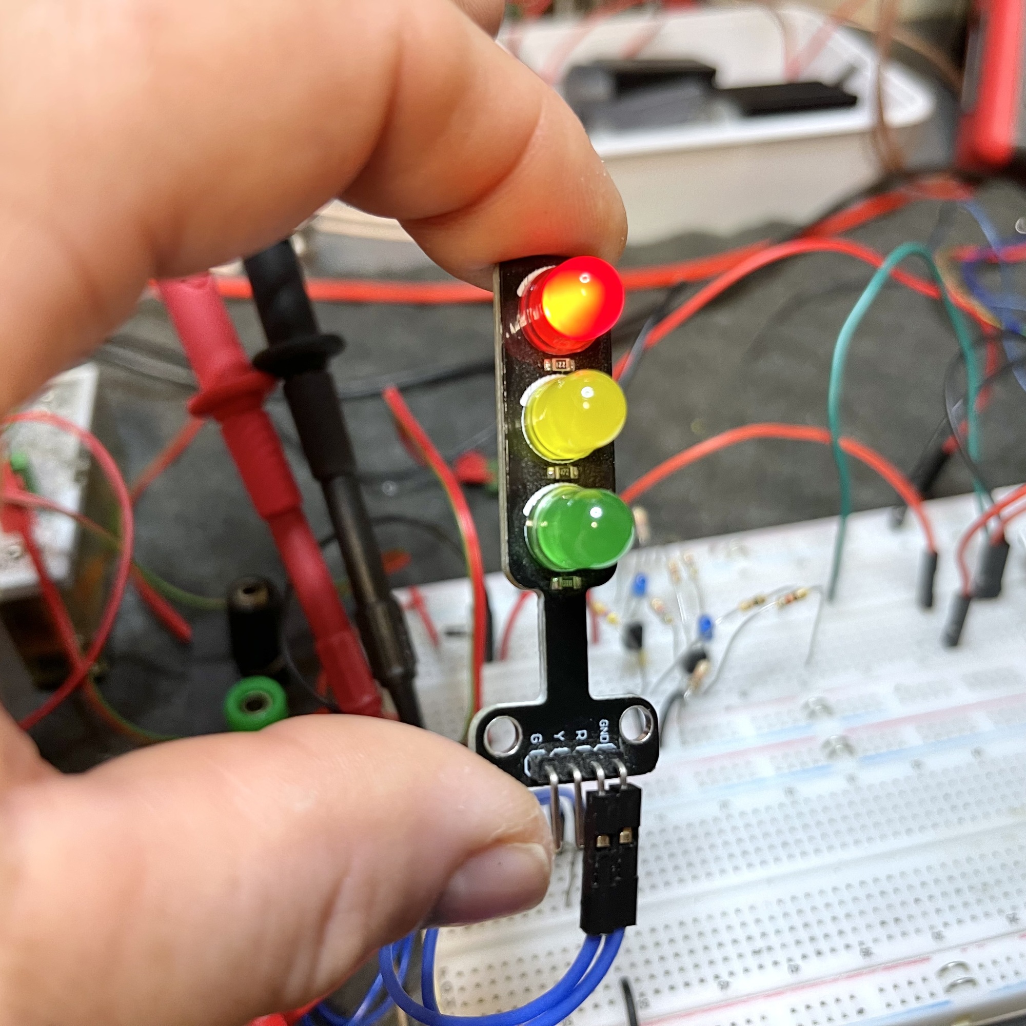
While browsing through the microcontroller gadgets and electronics modules offered online, I came across a model traffic light with three large LEDs. The module consists of a red, yellow and green LED including their necessary series resistors brought together on a small circuit board. After some modifications it turned out to be relatively easy to make a working traffic control for two directions with these funny PCBs. The use of a microcontroller is of course obvious, but probably the traffic lights also lend themselves perfectly to the visualization of traffic controls that are build from classical discrete electronics, or even electromechanical solutions.
The LEDs on the board share a so-called “common cathode,” so only one common minus pole needs to be connected. The product description already indicates that the boards should be suitable for 5 volts, so in principle they should be able to be driven directly by the digital outputs of a microcontroller, such as an Arduino or Raspberry Pi.
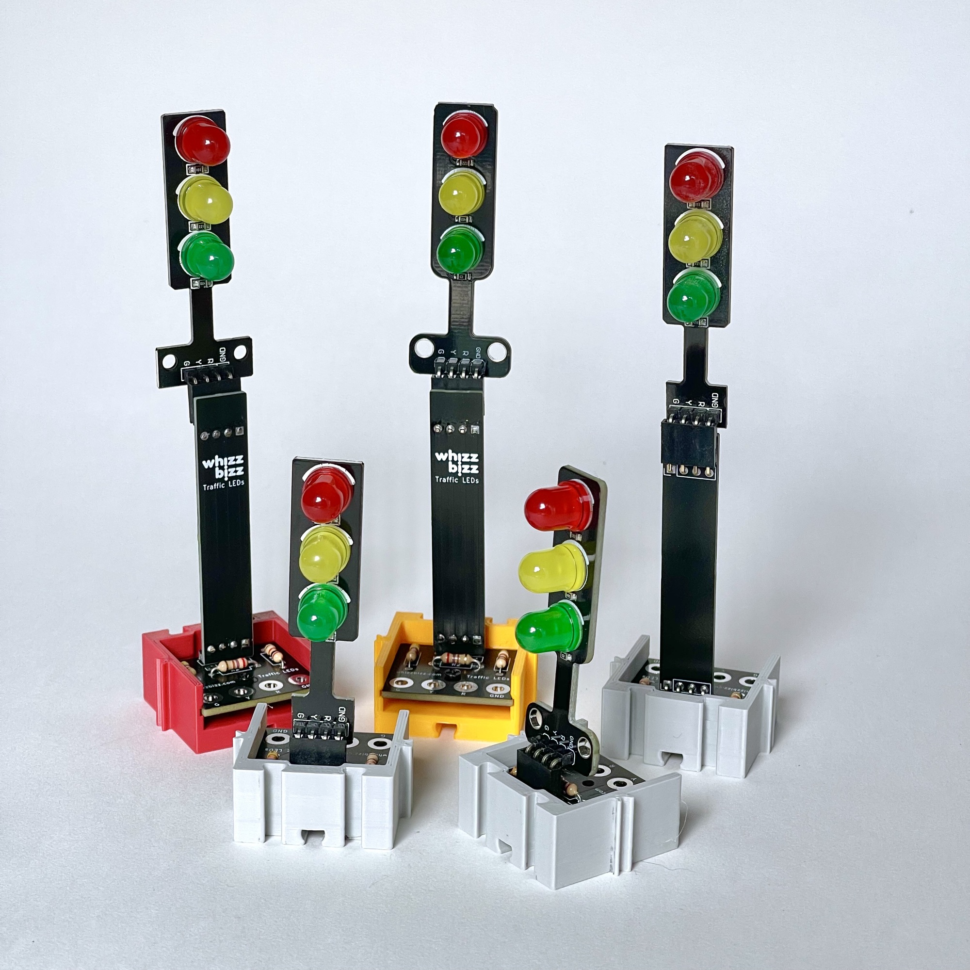
Since I could imagine that they would also be suitable for 9-volt operation with some modifications, I later ordered a few more. Afterwards, it turned out that I had ordered from two different dealers. And although both the product description and the title “Mini 5mm LED DC 5V Traffic Light LED Display Module Board for Arduino Mini-Traffic Light for Traffic Light System Model” matched completely, the boards turned out to be slightly different.
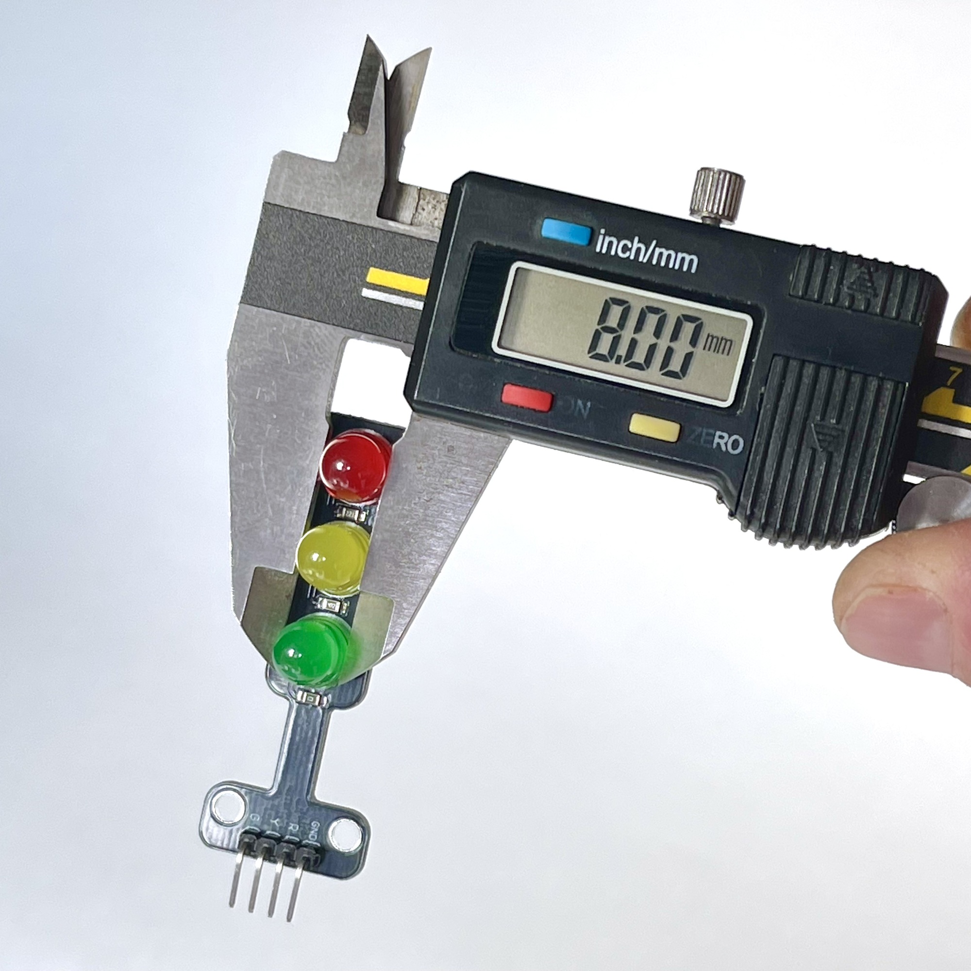
I had noticed before that many advertisers online blindly copy all photos and specifications from each other. Hence, I was pleased to note that the 5 mm LEDs mentioned in the description turned out to be the 8 mm ones I already recognized in the photos. So it is miraculous that the dealers themselves do not even measure (or understand?) what they are selling.
The PCB dimensions of the two types of PCBs turned out to be fairly similar, but there were some physical differences. For example, of the model with the rounded corners, which I will call 'PCB 1' further on, the mounting holes are real so-called via's with copper in the hole, while on the model with the angular PCB shape ('PCB 2') these are simple M3 drill holes.
From the specifications of both modules, it would be fair to say that they were both designed for 5 volts. And the 'operating currents' for the different colors are exactly the same for both boards was specified as: Red 13mA, Yellow 13mA, Green 25mA. That last value already seemed rather high to me because specifications of 8mm LEDs I found online showed that similair green 8mm LEDs should draw a nominal current of about 20mA at an operating voltage of 2.5 volts. And then again, 25mA for the green LED by itself seems relatively much. After all, the maximum output current of an Arduino output may be 40mA, but in practice 20mA is held as a practical limit.
So I first tried the stop lights just on 5 volts, also because I was curious how much current they drew and whether the three colors were more or less about the same brightness. Spoiler: they're not. The first thing to notice here is that the red LED on both models is actually almost too bright. [click on the table to enlarge]
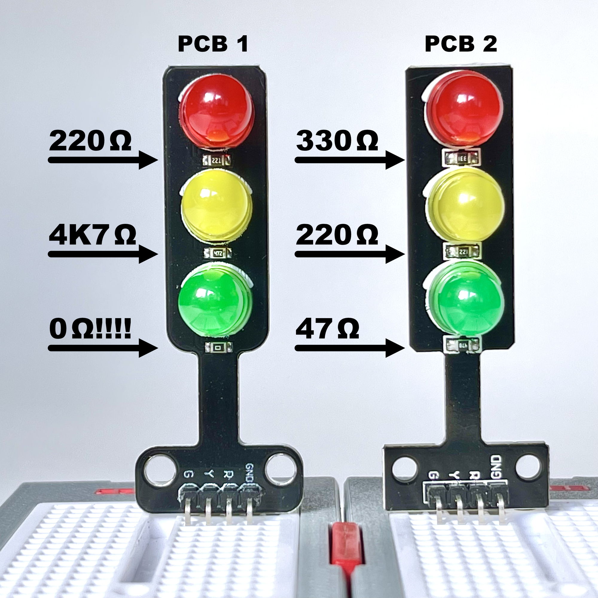
Because I was interested in how (and if) the brightness of the different LED colors was balanced, I studied the values of the SMD series resistors on the PCBs.
To my dismay, I had to conclude that the 'PCB 1' PCB has a 0Ω SMD resistor, actually just a jumper, as a series resistor for the green LED. This LED is thus directly connected to 5 volts and draws more than 110 mA! Since the nominal voltage across such an LED is only 2.4 volts, this LED will probably not have a tremendously long life. If you drive it directly from an Arduino, there might even be the question of what dies sooner: the respective output of the Arduino or the LED! The table above gives the values of the series resistors that had been used on my two different boards.
The tentative conclusion is that the first model board, with the 0Ω series resistor for the green LED, is not very useful in its current version for direct use on an Arduino and/or 5 volts. On the other hand, a far too large series resistor of 4K7Ω is soldered on this board for the yellow LED. This will have to be adjusted if we want this LED to be a little more visible and brighter and we want to balance the brightness of the three LEDs of this little traffic light at 5 volts a bit.
If you don't want to go changing SMD resistors, I recommend using this mini traffic light only on a 9 volt supply voltage with some added series resistors. See my findings further below.
On the other PCB model, the green LED does have a small, only 47Ω, series resistor but there the current flow is too high (~30mA) because the voltage across this LED is too high (~3.7 volts). So also not recommended to use this board directly at 5 volts. However, by adding additional resistors, it would be possible to make this board usable at 5 volts.
The picture shows the SMD-series resistors I found on my various boards, I assume that these may simply differ per order, or production batch! So please check first!
Before I started unsoldering and swapping SMD resistors, I thought it would be useful to identify which additional series resistors might be used to somewhat balance the brightness of the three colors.
After all, this would also solve the complete lack of a series resistor on the board itself. Experimentally, I determined these values for both 5 volts, for application with microcontrollers, and 9 volts for future circuits built from e.g. more concrete electronics or fischertechnik modules. [click on the table to enlarge]
However, the series resistor of the yellow LED on 'PCB 1' is way too high. Without desoldering and changing this SMD resistor it will always actually remain poorly visible at 5 volts. On top of that, the green LED is clearly not a low-current type. We could, by adding a series resistor of 150Ω ourselves, limit the current through the green LED to a value below 20mA. But at that current this green LED still burns relatively dimly. Because of this, it does not seem so easy to somewhat bring the luminosity of this color anywhere near the same level of the red 'low-current' LED of that same traffic light.
The other board, “PCB 2,” actually also has a rather large resistor value soldered on for the yellow LED, but we could take the brightness of this LED as a starting point. By including an additional series resistor of 1KΩ for the green and red LEDs, the brightnesses of the three colors are more or less balanced at a supply voltage of 5 volts. The green and red LEDs seem to be so-called low-current types with a high brightness at very low currents.
At a supply voltage of 9 volts, the brightness and visibility of the yellow LED on 'PCB 1' even becomes acceptable. An additional series resistor, as for the green and red LED, is not necessary for this board. See the values in the table for resistor values of which I personally think that the brightness of the three LEDs did not vary too much.
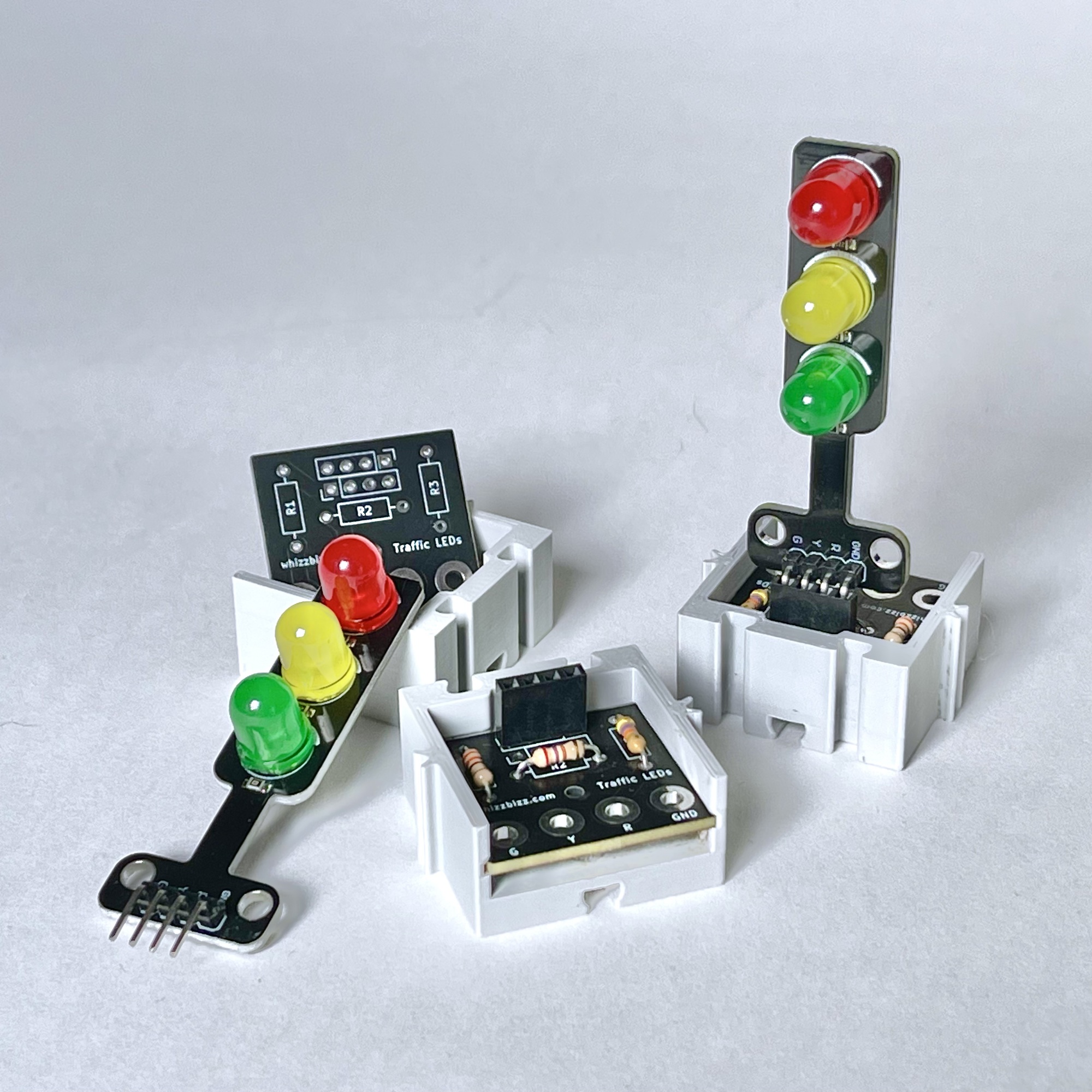
So, since there are apparently differences in brightness and pre-assembled series resistances of the various LED traffic lights, I thought it would be useful to design a small PCB on which the series resistors and brightness differences could be adjusted depending on the application. For future 9-volt projects, I thought it would be useful if the 2.5mm fischertechnik connectors could be connected directly to the PCB.
I duplicated the four-pin Dupont headers on the PCB to enable the traffic light module to be mounted in both directions. The traffic light board model 'PCB 2' seemed the most useful to me. The yellow LED then did not need an additional series resistor and the brightness of the other two LED could be balanced accordingly. I also designed an additional 'riser board' with which the traffic light could be extended another 6 centimeters.
Finally I designed a small casing with grooves for the fischertechnik system. Once that was all done, the experimenting could begin.
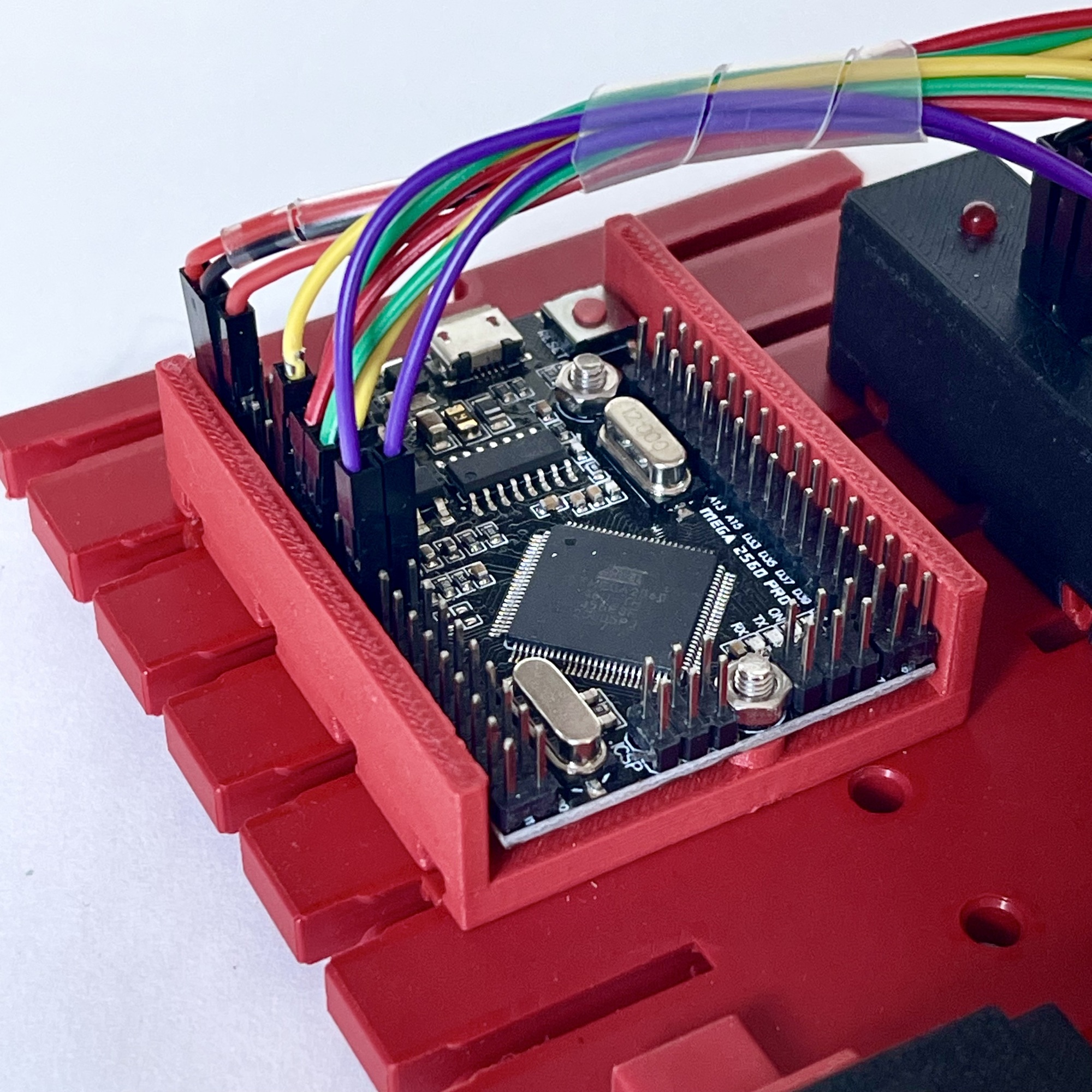
To control the traffic lights, I used an Arduino Mega Pro Mini. To build the experiment with the fischertechnik system, an enclosure designed for this purpose for the Arduino came in handy (see rightmost photo above).
A 'traffic control' for one traffic light appeared to be quickly made. It was a nice test for “Duino Code Generator,” which can make suggestions for Arduino software using Artificial Intelligence (AI). After entering the descriptive definition “Generate a program to control 3 LEDs like a traffic light” a program was shown that allowed itself to be uploaded into the Arduino used by the one I used for this project without compile errors. After connecting the three control signals for the LEDs to pins D2, D3 and D4 and connecting the common ground of the traffic light, this indeed turned out to produce some sort of traffic control. At least the three LEDs of the mini traffic light came to life.
The LEDs were driven alternately. However, the duration of each step was hard-coded, and more importantly, the sequence was still not quite right. Still, such a jumpstart obviously already gives a nice starting point where a working result is immediately achieved that can be easily adjusted afterwards by yourself.
After some “intellectual fine tuning” of the first automatically generated software, I tried how far the AI Code Generator would get at controlling two mini LED traffic lights for two different traffic directions. The input this time was “Generate a program to control two traffic light poles with 3 LEDs each for traffic control of two traffic directions.”
The result was a long way in the right direction, proposing to connect the three additional LEDs to pins D5, D6 and D7. However, the software was not very economically programmed. For example, it included a separate function for each lamp that turns on only that lamp and turns off the other two. Worse, the code was syntactically flawed. The commands for configuring the Arduino pinModes for the output pins used caused compiler errors. After manually moving this piece of code within the setup() routine designated for this purpose, the program could be compiled and uploaded. However, the control of the two traffic lights then had to be extended and corrected by hand, as in the previous example.
The proof of concept had succeeded. The usability of the small LED traffic lights had been demonstrated, but the sequence in which the lights light up sequentially and their timing was still completely fixed in the mainly automatically generated software.
However, the cycle in which the colored lights alternate or illuminate simultaneously differed from country to country. In the Netherlands, two bulbs of a tri-color traffic light never light up at the same time. Here, the red light jumps directly to green. In many other countries, such as Sweden, Great Britain, Austria or Germany for example, before the red light turns green, the orange light is first illuminated in combination with the red light as a sign that the green light is coming and one can already drive on.
It would be more useful if the traffic control could be configurable such that different controls could be called up at the push of a button. I decided to build the software a bit more flexible and intelligent and use two touch switches for configuration. The idea was that the left switch should allow to choose between the “Dutch” and the “German” traffic control, and that the right switch if activated would override this setting with a simple blinking behavior of the traffic light. For this, in addition to scanning two additional inputs to make the touch switches operative, the program would preferably have to store the entire lamp sequence and timing of it in configurable arrays.
Hoping to quickly obtain a syntactically correct basic program, I tried the “Duino Code Generator” with the phrase “Generate a program to control two traffic light poles with 3 LEDs each for traffic control of two traffic directions. The lamp-sequence and timing must be configurable in an array of structs.”
The result was a syntactically correct, but unfortunately rather cluttered program. While the necessary configuration of the LED pins was correctly placed in the setup() function this time, the “structs” were at the traffic light level and therefore contained only the necessary three parameters for the three lamps. The timing of the different lamps was contained in arrays.
In contrast, my starting point was a more coherent structure where each individual step in the lights sequence of a traffic control is contained in a struct. That way, a duration and the lighting or not lighting of each of the six lights could be configured for each step in one array item. So, by creating an array of these structs, it would then be possible to very flexibly configure different “traffic controls". Ideally, the definition of a structure of a 'step' should be something like the definition of the struct lightsStep below.
The boolean in this struct indicates with a value 'true' or 'false' whether a lamp is lit or extinguished in this step or 'state'. With an array of these structs, we can then configure each of the three desired traffic control sequences as an array as shown on the right.
Here, trafficControl_nl is the traffic program with a typical Dutch lamp sequence. In the traffic program trafficControl_de, the second and fourth steps are modified so that the yellow lamp joins the red one before the green lamp is lit in the next step and the red light is lit for the other direction of travel. Finally, trafficControl_blink is a program in which the yellow lamps flash alternately. This mode is often used when the traffic lights are not in operation.
In the final program, or video, you can see how, based on the defined arrays, the traffic programs are run during the execution of the program.
// Define struct for traffic light sequence
struct LightsStep {
  int duration; // Time in ms for this step in the sequence
  bool red1;    // Red light 1
  bool yellow1; // Yellow light 1
  bool green1;  // Green light 1
  bool red2;    // Red light 2
  bool yellow2; // Yellow light 2
  bool green2;  // Green light 2
};

// Define array of structs for traffic light sequences
LightsStep trafficControl_nl[] = {
  { 5000, true, false, false, false, false, true }, // Red1 & Green2 are on...
  { 3000, true, false, false, false, true, false }, // Red1 stays, Green2 --> Yellow2...
  { 5000, false, false, true, true, false, false }, // Green1 & Red2 are on...
  { 3000, false, true, false, true, false, false }  // Green1-->Yellow1, Red2 stays on...
};

LightsStep trafficControl_de[] = {
  { 5000, true, false, false, false, false, true }, // Red1 & Green2 are on...
  { 3000, true, true, false, false, true, false },  // Red1+Yellow1 are on, Green2 --> Yellow2...
  { 5000, false, false, true, true, false, false }, // Green1 & Red2 are on...
  { 3000, false, true, false, true, true, false },  // Green1-->Yellow1, Red2+Yellow2 are on...
};

LightsStep trafficControl_blink[] = {
  { 800, false, true, false, false, false, false },  // Yellow1 & Yellow2 on...
  { 800, false, false, false, false, true, false } // All lamps off...
};

uint8_t controlSequence = 0; // 1=nl, 2=de, 3=blink. Set to 0 to force initialisation...
uint8_t SequenceStep = 0;    // Current step/state in the sequence...
int SequenceSteps;           // Number of steps in the active sequence. This is size/8 because each struct has a size of 8 bytes...
LightsStep *currentSequence; // Pointer to the current traffic control sequence...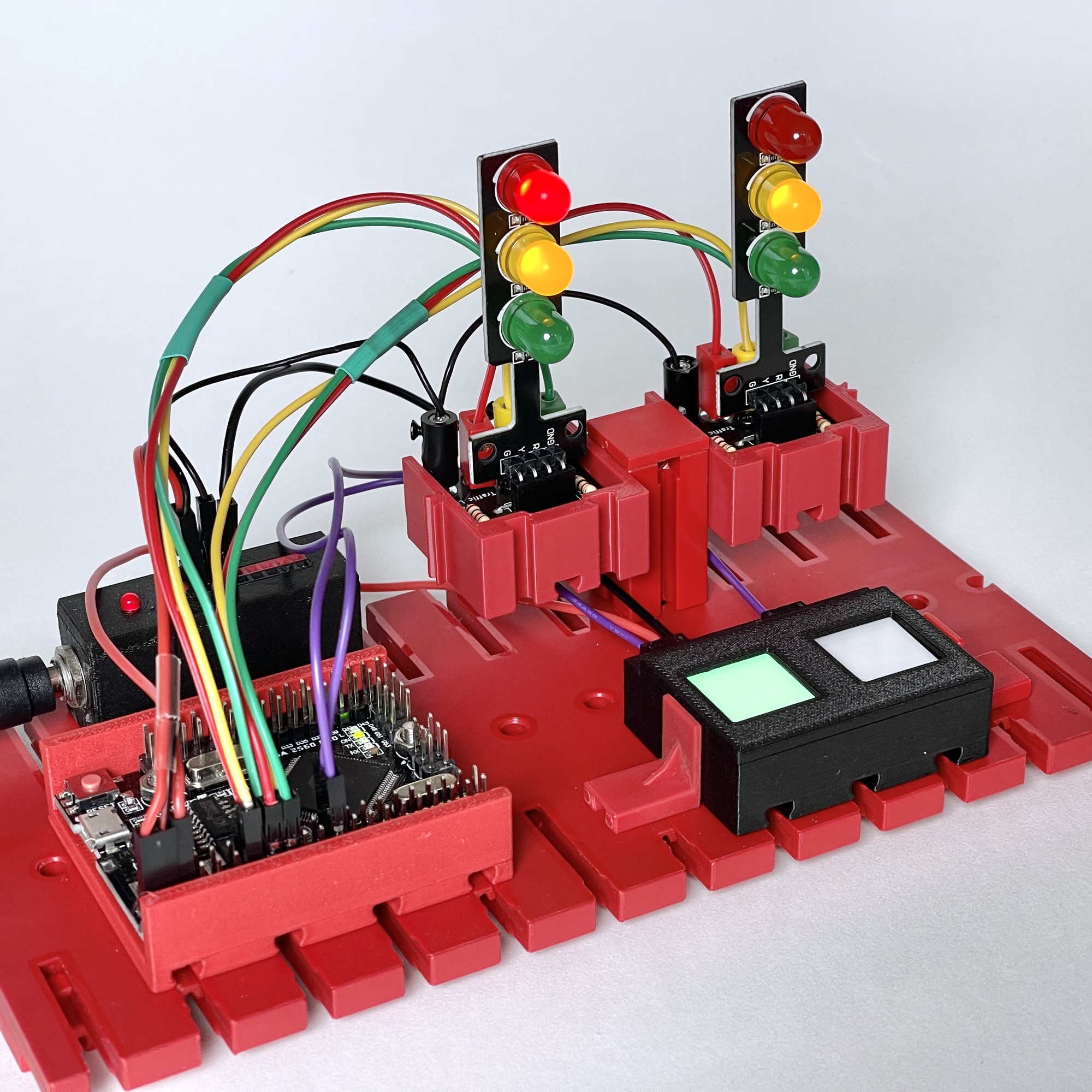
The Arduino controls the six different LEDs via the Input/Outputs D2 through D7 configured as outputs. In a previous project I already experimented with HTTM touch sensors. Connecting and using these with an Arduino or other microcontroller is straightforward. An advantage is that the touch sensor itself can already be configured to work as a toggle switch. The first touch activates the switch, the next touch deactivates it, and so on. No additional provisions need to be made for this in the Arduino software. Nor does the switching noise of a physical switch need to be suppressed in the software.
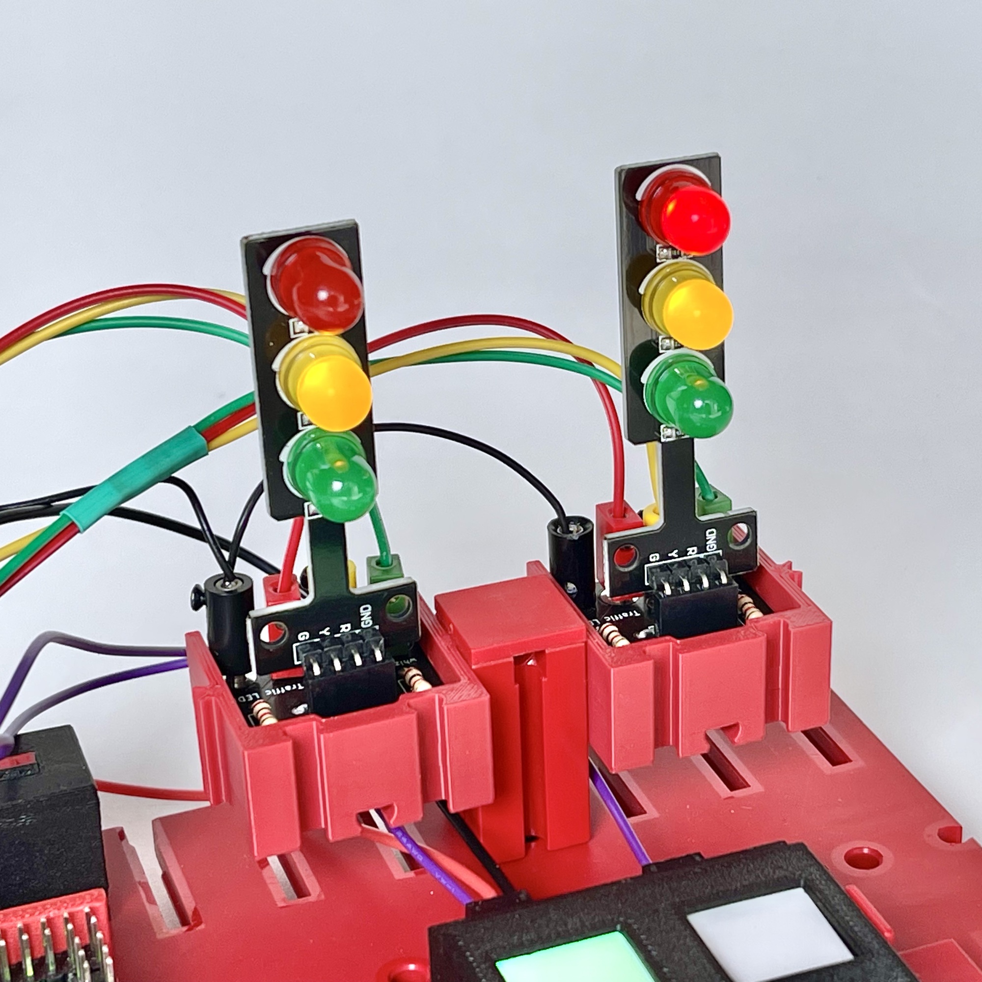
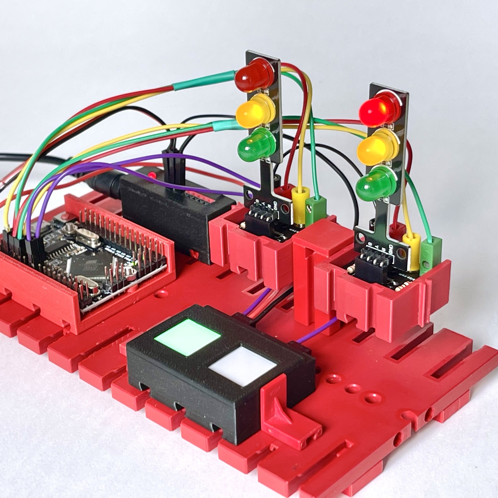
The picture shows the complete setup of my traffic light experiment. The two touch sensors were connected to inputs D12 and D13. As mentioned, I used an Arduino Mega Pro Mini, but of course the circuit can also be built with an Arduino Uno, Nano, or any other microcontroller with at least 2 inputs and 6 outputs.
I opted that when the left touch toggle-switch is activated, the program switches from the typical “Dutch” to the “German” traffic control. The right touch switch has a higher priority. When activated, the yellow lights flash alternately in 'service' mode. Below is the Arduino Sketch of my experiment in which it may be easy to make the changes for your specific situation.
The “Mini 5mm LED DC 5V Traffic Light LED Display Module Board for Arduino” LED boards offered online are very useful for experimenting with traffic controls. But before you connect them, check what series resistors the manufacturer has soldered in. If values are too high, the corresponding SMD resistor on the module itself will have to be replaced, but if values are too low (like the 0Ω found on my boards!) this can be corrected with additional resistors on the small circuit board I developed for this experiment.
This small circuit board, mounted in the small building block (to be used with fischertechnik), may serve as a base for the small traffic lights boards. The 2.5mm plugs of the fischertechnik system can be connected to it directly. But of course it is also possible to solve this simply by placing the traffic lights on a breadboard or small piece of experimental circuit board.
It was relatively easy, especially with the headstart provided by the 'Duino Code Generator', to quickly build a working traffic control with the small LED boards. The touch switches are a useful addition for 'live' switching between the different traffic controls. A possible future extension could be a potentiometer on one of the analog inputs to adjust the speed of the sequence. This I leave to you!
The Arduino Sketch can be downloaded above. The STL files of the Arduino Mini Mega holder and the building block for the traffic light can be downloaded from Printables and Thingiverse. Those looking for the Gerber files of the small circuit board can find them on GitHub. There, everything can also be downloaded at once as a collection. Just contact me if you're looking for individual parts such as the circuit board, a kit or the ready built traffic lights. I am of course happy to help with any customization.