I always try to finish my homebrew electronics modules with as professional-looking faceplate as possible. After being fitted with the necessary openings and holes, this should ideally be able to be glued into a slightly recessed part of the final faceplate or lid. In recent years, I have found several ways to print such a lid with raised edge all around.
However, the most obvious printing method takes a lot of support material, relatively a lot of post-processing and does not produce the smoothest surface of the recessed part. Finally I found a method that works well for me without all these disadvantages.
I regularly use my 3D printer for printing enclosures for electronics modules or projects. Eventually the LEDs, dials or sockets stick through the lid, or one of the sides, of such an enclosure. A recurring challenge is how to shape the captions, scales, etc. around these controls and connectors.
With most mass-produced devices, the texts and captions are on the thinnest possible faceplate glued to the front or casing. I myself have already tried anodized aluminum (outsourced relatively expensive, quite a hassle if done yourself), silk-screen text on a circuit board (rather low resolution text only) and laser engraving (damages quickly when manually reworked), but each of these methods has its own drawbacks.
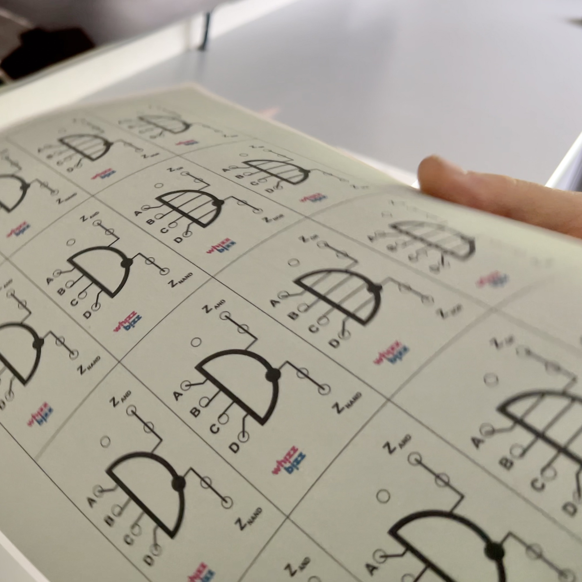
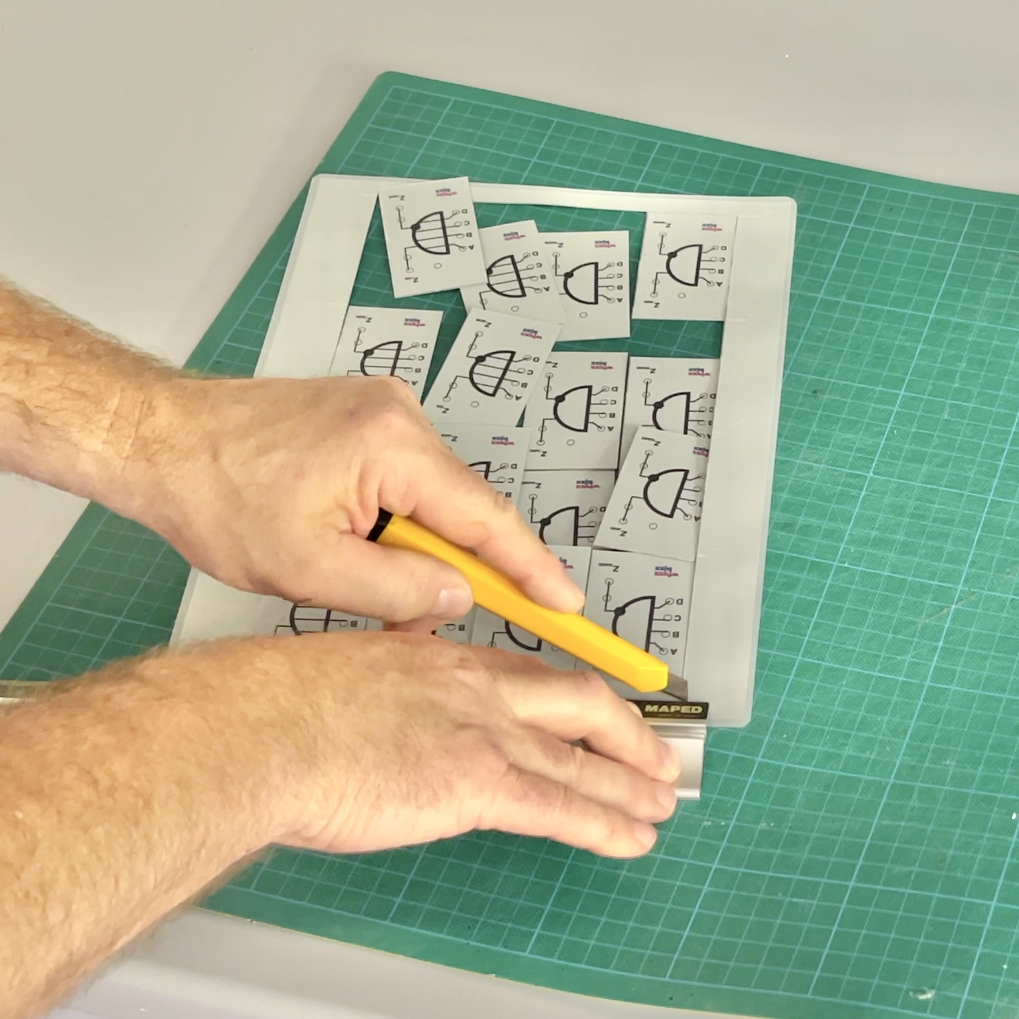
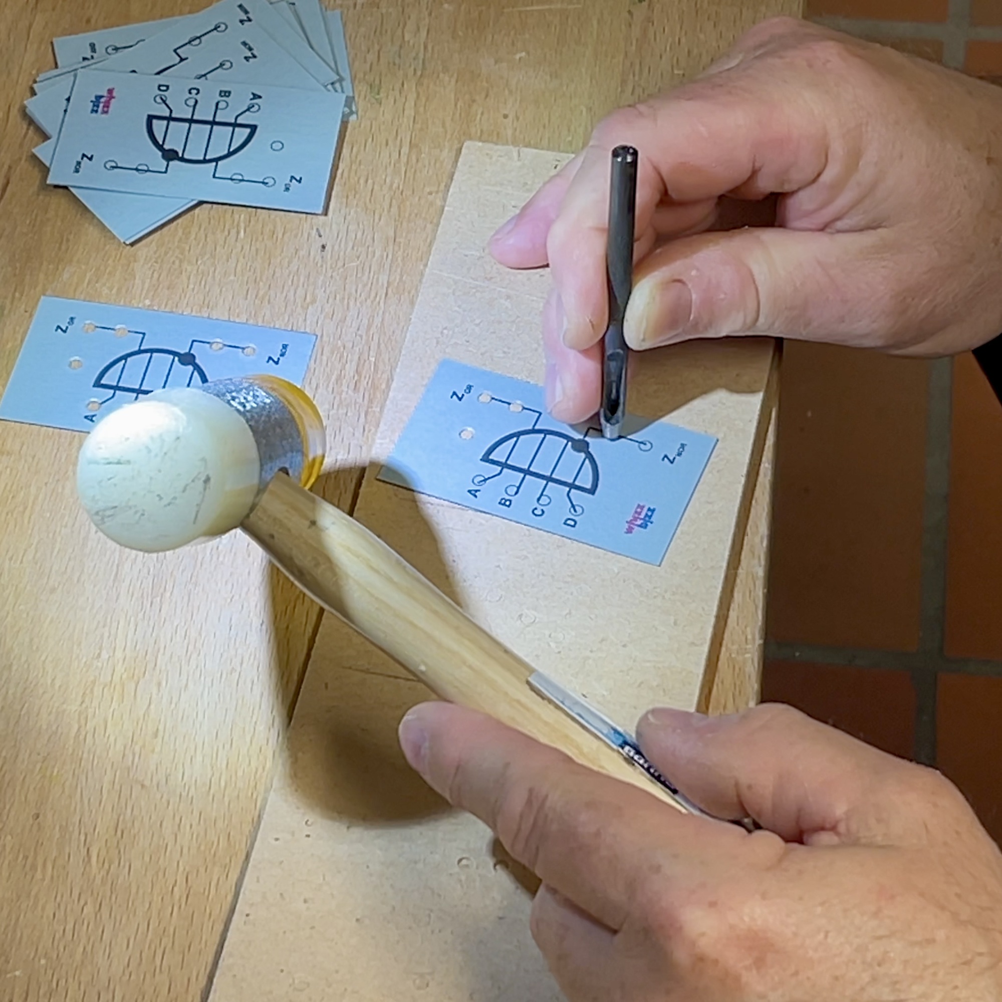
Lately, I have been making these faceplates simply on the laser printer. I print them, in color if desired, on aluminum-colored paper, which I laminate with a matte lamination cover. That way, the faceplate is less susceptible to dirt. After cutting the individual faceplates loose, I punch the round holes with a hollow punch and cut out the square openings by hand. Then I literally iron the foil around the openings with a not-too-hot iron. That way, the holes become nicely round and the adhesive strength around the cuts and punched out holes is restored.
Despite this, of course, these laminated paper faceplates remain relatively fragile, especially at the corner points. For best protection, it would therefore be nice if the plate could be glued slightly recessed into the lid of the case. For this, a lid would then ideally be printed on the 3D printer with a recessed area the size of the faceplate.
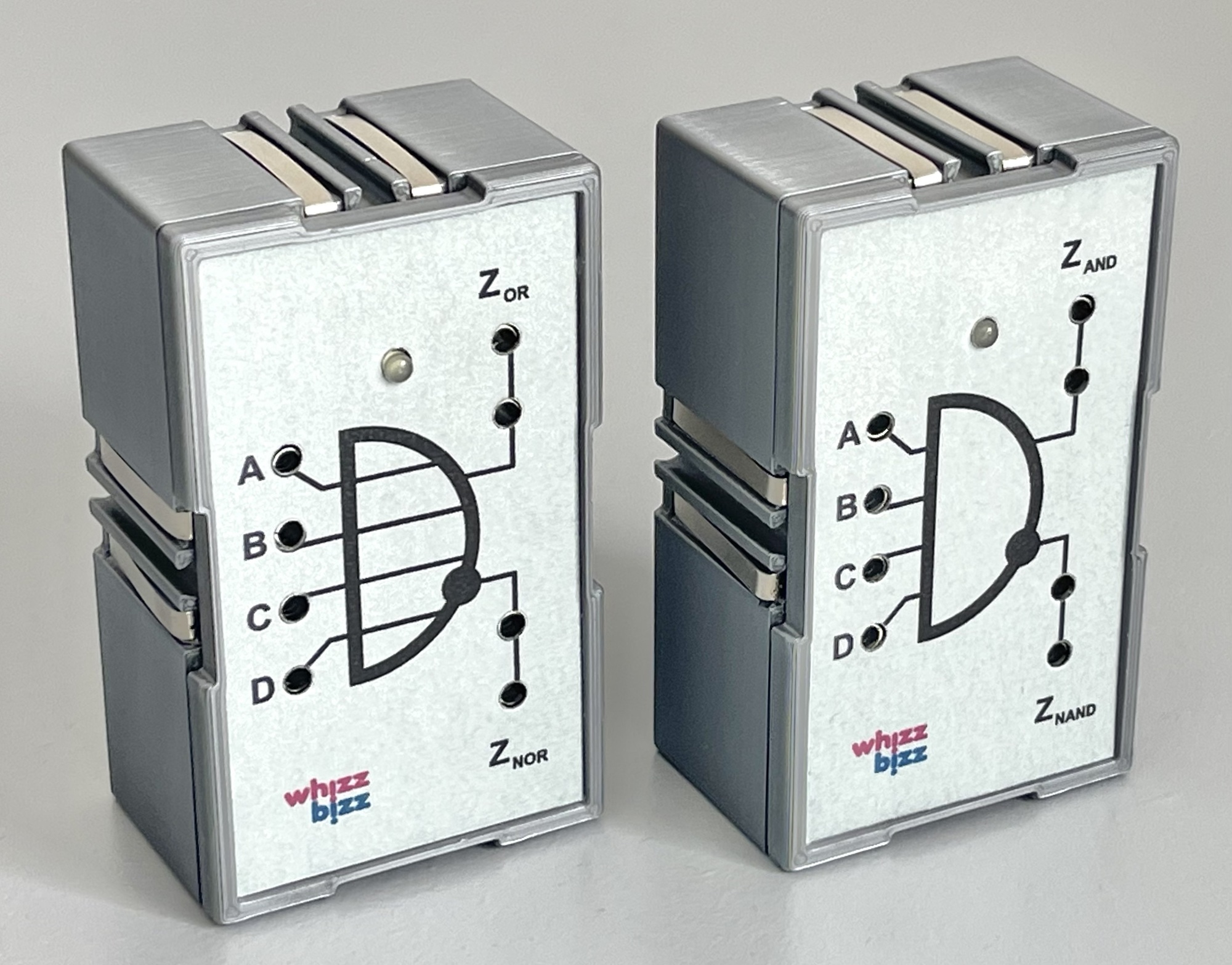
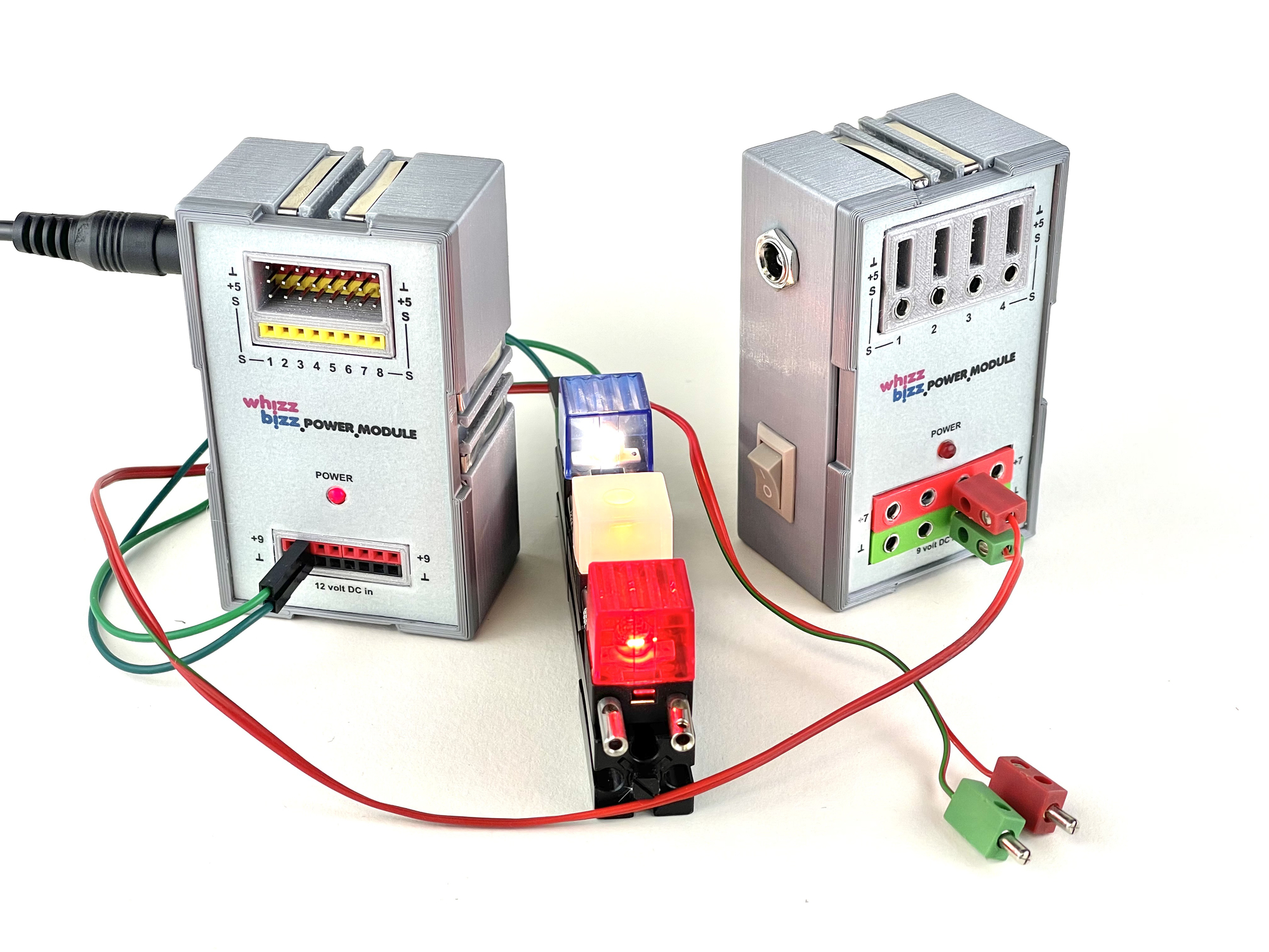
A good example are my own self-built electronics modules, such as the recreated 'Silberlingen' by fischertechnik and the various power supply modules I designed. The traditional 'Silberlingen' used anodized aluminum etched front plates. For single pieces, however, this is a rather expensive solution. Moreover, an additional disadvantage is that the holes around the connection sockets must be relatively wide, because the aluminum is conductive. This is something I don't have to consider with my non-conductive faceplates made of plastic (and paper). The only challenge was to find the most efficient printing method where this faceplate can be glued into a slightly recessed area of the lid.
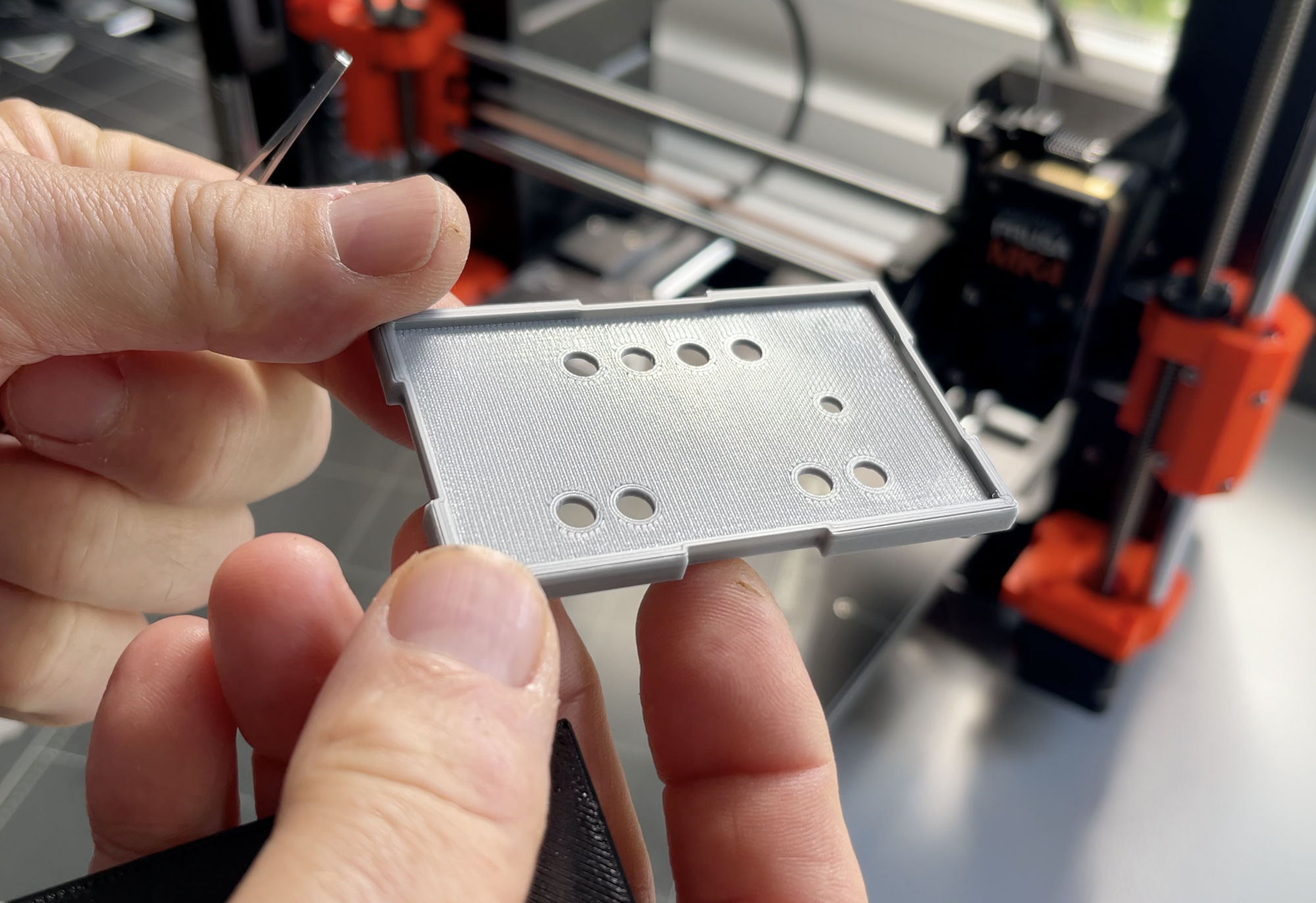
Those who want to print such a lid with the 3D printer run into a problem. After all, only the part printed directly on the printer bed can be printed nice and smooth. And, because there are four legs for the mounting screws on one side of the lid, the front side is the designated "flat side" that will have to be printed on the bed. So the lid will have to be printed upside down, but in doing so, the recessed part will have to be supported during printing by support material to be removed later. This is not efficient. Moreover, to remove the support structure afterwards, the recessed part must be at least 1mm deep. Moreover, after removing the support material, the final surface of the recessed part is relatively rough. This actually precludes the use of too thin sticker material or laser foil for the faceplates.
A first alternative I tried was to print the border separately. This can then later be glued to the front of the lid. One advantage is definitely that the front is beautifully flat, but it is always quite a bit of after-work where you really have to be careful not to glue your fingers as well. When the housing is relatively small, as here only 45 by 75 mm, and the final loose edge only thin and fragile, this is still not really easy.
Moreover, the seam remains slightly visible anyway. For single pieces a useful method, but for small series production not optimal. For series production, a special "stick-on tool" that makes it easier to align and clamp the edge would be worth considering. It was actually clear fairly quickly that this was not yet optimal.
This is why I tried the idea of separate printing the eventually deeper part of the front plate. The idea was to print this (can be "in place" where it remains a loose object), then press it a little deeper in and secure it from behind with super glue. This way of mounting is of course not very strong. If components, such as a potentiometer for example, are mounted on it through the holes on which forces can be applied, this glued in deeper part may eventually break loose.
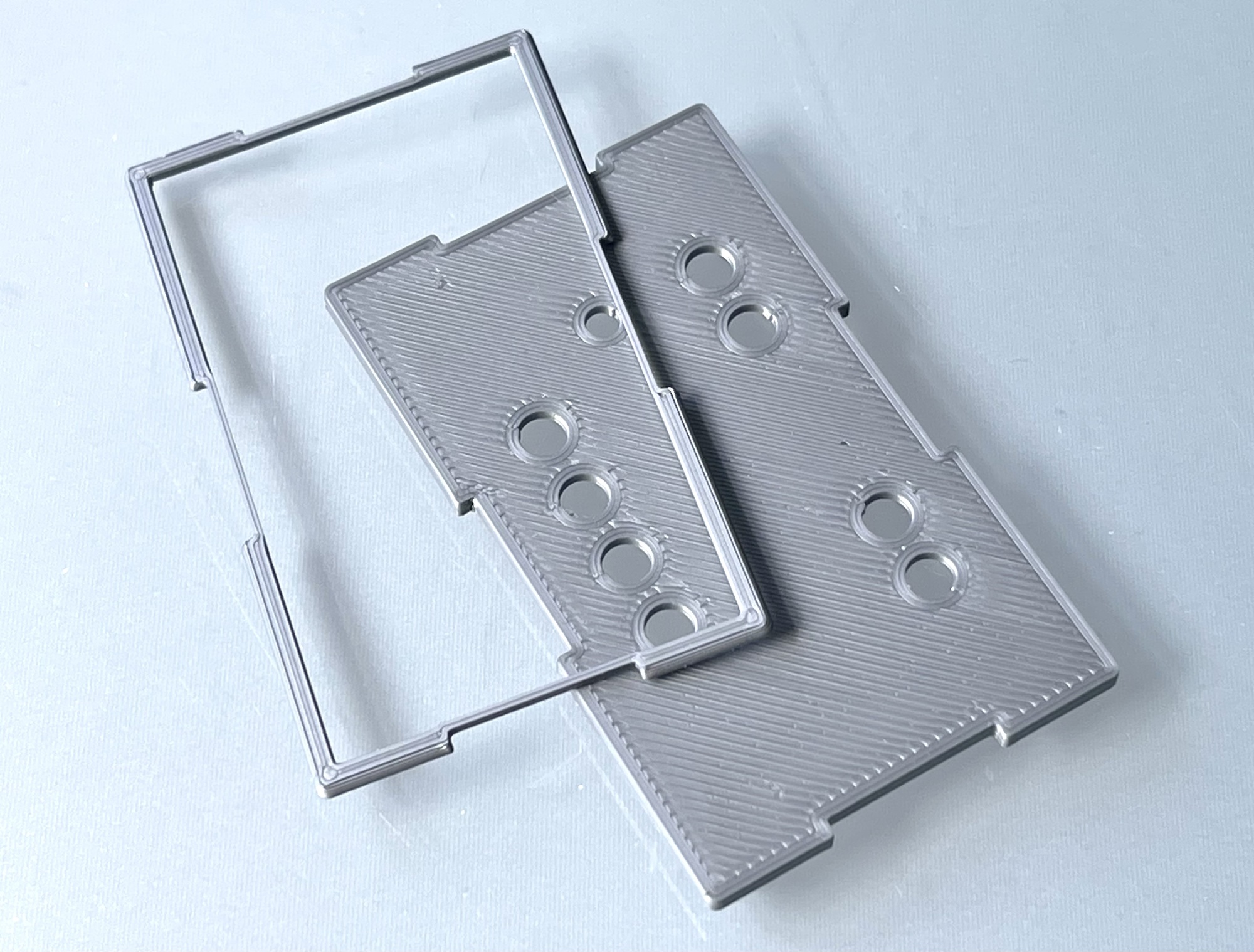
An improvement on this idea was to print small "support corners" that support the deeper part of the front, to which it can be glued and secured with a drop of glue. See photo to the right of the back. This is a great method that produces a neat smooth deeper area because it can be printed on the printer bed. So in the end this surface is neatly smooth. Perfectly usable and even immediately ready in enclosures where no separate front panel with captions is needed.
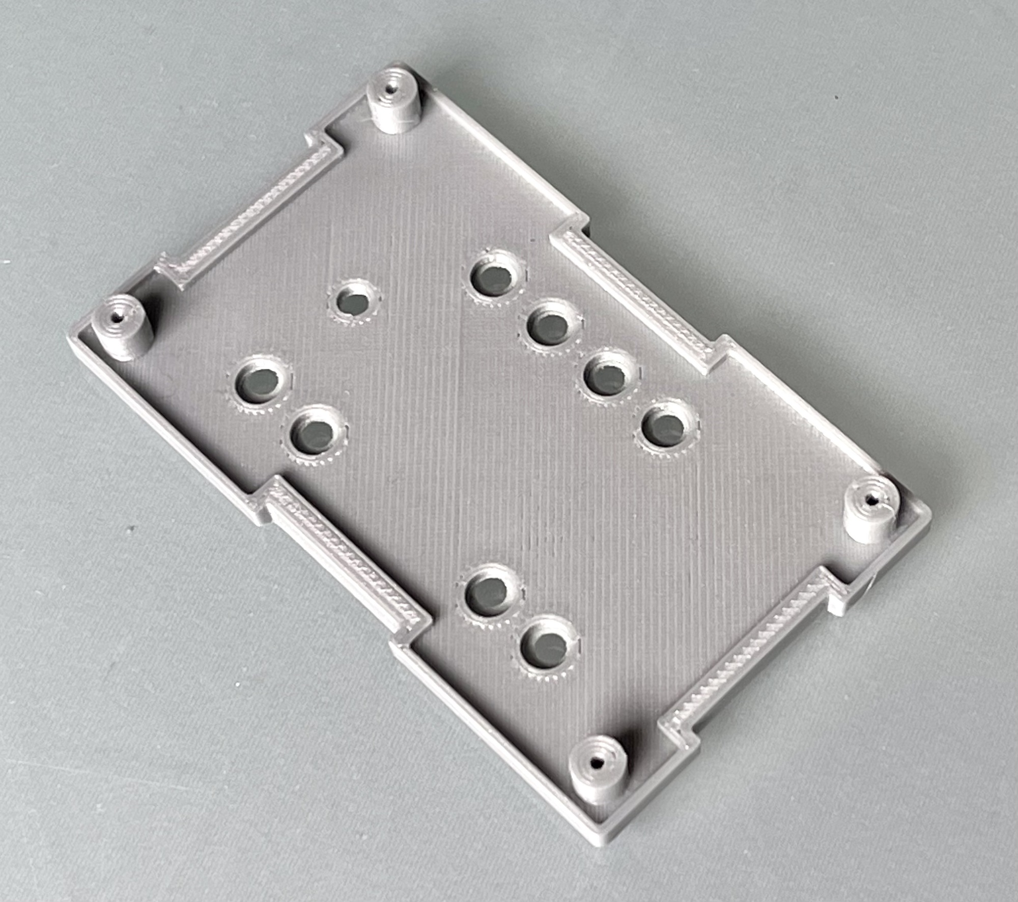
However, this method is more difficult to use for a lid with a relatively thin surrounding rim. Or where mounting feet are printed on the back. Moreover, the recessed area must still be glued in afterwards.
Printing the lid the other way around, with the final back/inside on the print bed, would of course be a solution, but then the mounting feet would have to be dropped and countersunk, later less accessible, screws would be used. Also, the ridges around which the lid aligns itself with the case would have to be dropped.
The search for a printing method without support material, minimal post-processing and with a smooth recessed area was therefore still not over.
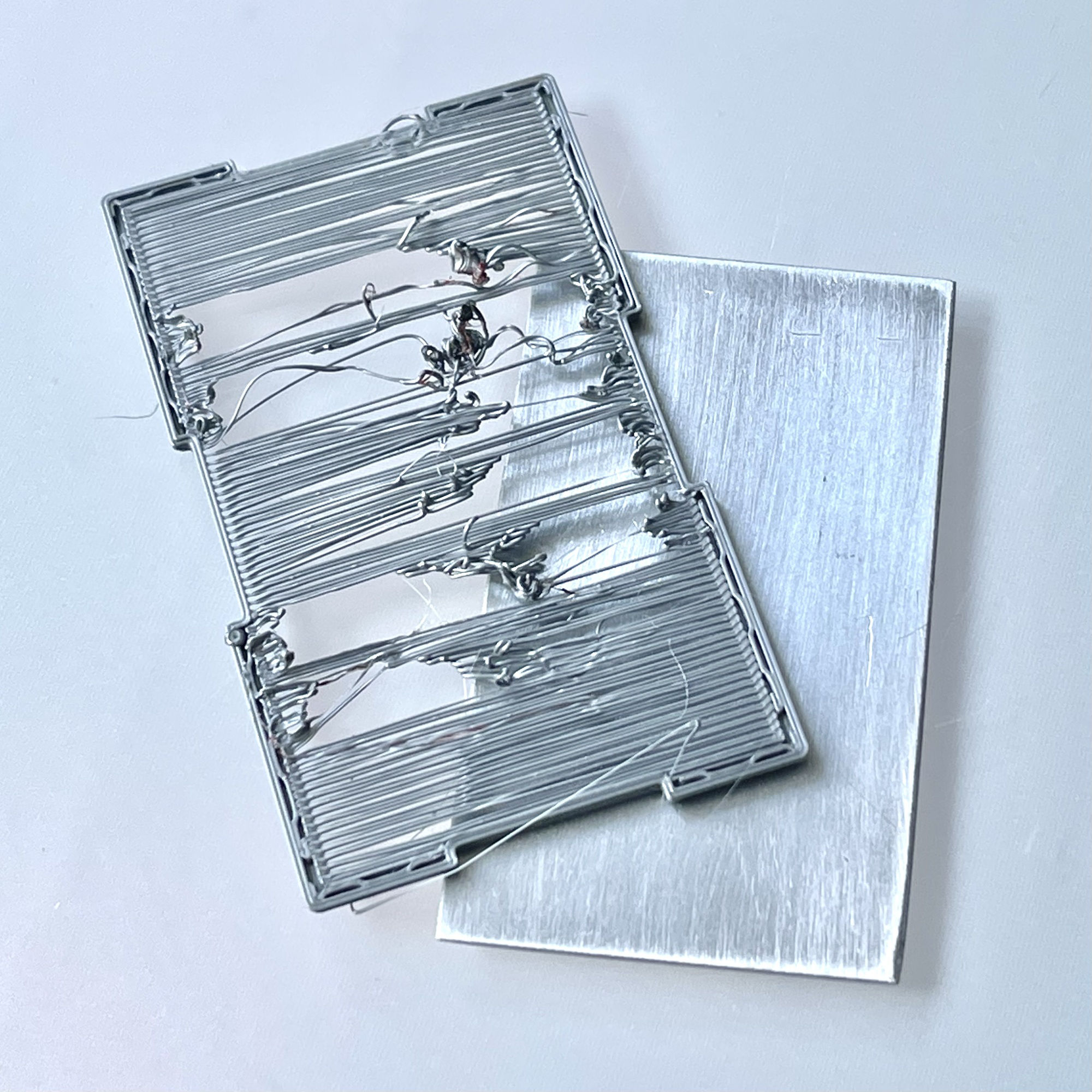
Printing a smooth recessed area up side down without backing material is quite difficult. Although the lid shown here is only 7.5 by 4.5 cm in size, the printer cannot "bridge" it to a smooth flat area without support material. To still save material or make it redundant, I devised an experiment with a custom-made aluminuim plate that, after printing the border, could be placed in the frame printed up to that point during a pause in the printing process.
But although the thickness of this sheet was very precisely 1.5mm (exactly the height of the border, after which the solid front can be printed) the adhesion of the following layers was not good. Special adhesion spray also did not offer a solution and these experiments remained disappointing.
It was clear that it would be better to use a plastic plate. Preferably with a slightly higher melting temperature than the PLA filament I use to print the lids. Since these plates could be printed on the same printer, it would also make it easier to experiment with the thickness of them.
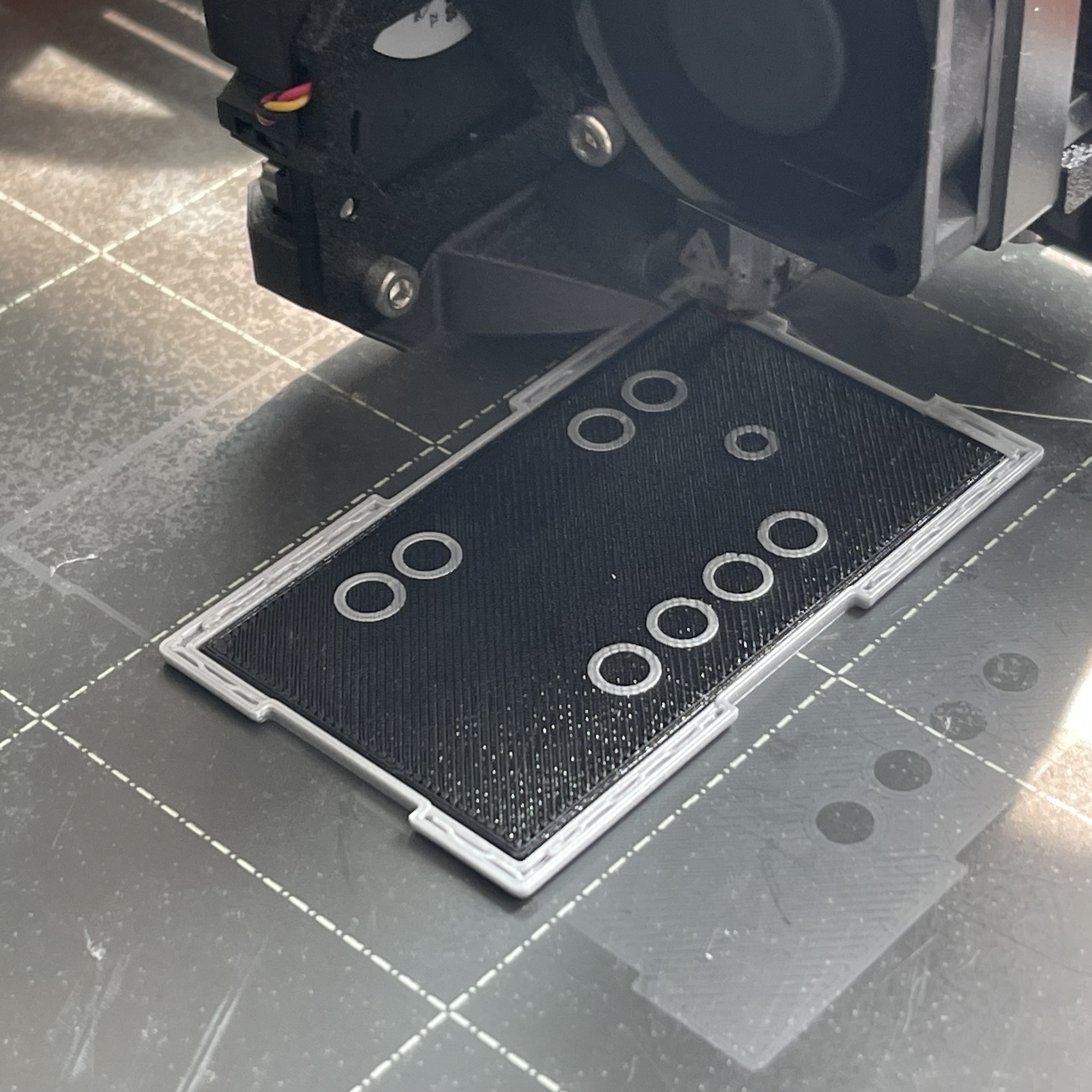
A great improvement was the use of a 1.5 mm thick PETG filament 'support-panel'. The results where much better than the experiments with the aluminum panel. Eventually I reduced the thickness to 1.4 mm and the adhesion of the subsequent layers and the result exceeded my expectations.
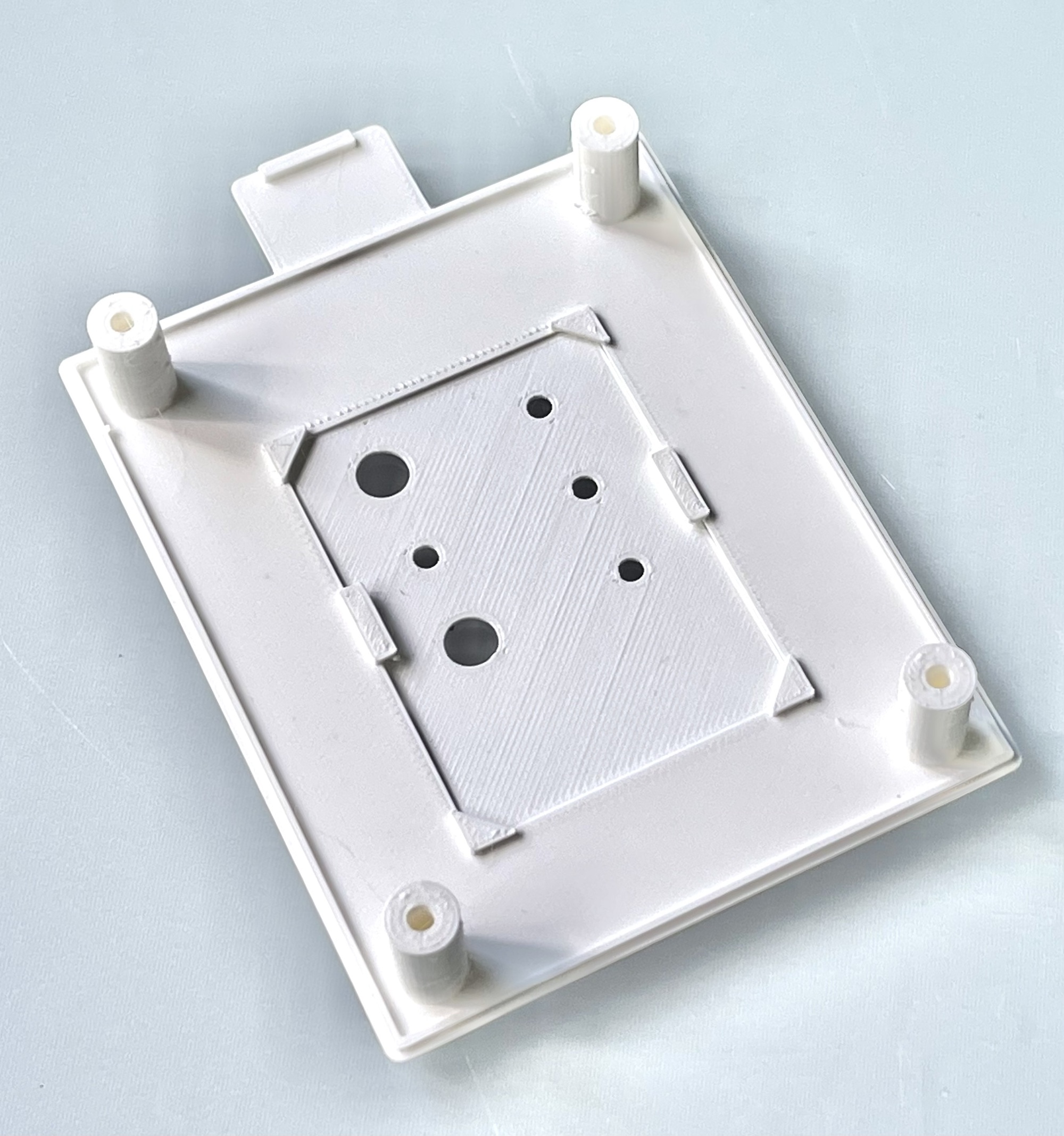
The temporary support plate can be very easily removed for reuse after printing and the surface of the deeper part is very nice and smooth while saving more than 26% material. Since this support material does not need to be removed and nothing needs to be glued, no finishing operations are required. The faceplate can be glued directly into the lid completing the finish.
The search had certainly yielded something. Depending on the housing and dimensions, I might still opt for loose printing and gluing in the deeper part, but for these small self-built modules, this PCB method is definitely recommended!