
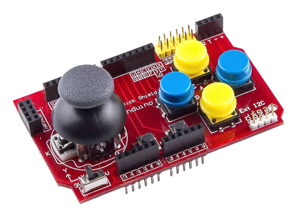
Recently I picked up a 'Funduino Joystick Shield V1.A' for a few bucks. This is an Arduino Uno compatible shield that allows you to create a game console or robotic controller. This nifty little shield features an 2-axis analogue joystick with switch, four large and two additional small switches (buttons) on the pcb.
Add an Arduino and some means of (wireless) communication to get a fully functional remote control unit and add game control or manual robot control type functionality to a project.
The features of the joystick shield (dimensions 3.4 x 2.05″) are:
The shield has a slide switch that allows you to select whether you are using it with a 5V board like an Arduino Uno or a 3.3V MCU like the Arduino Due. Be sure to set it to the correct voltage for the board you are using.
The X-axis potentiometer of the dual-axis joystick is connected to A0. The Y-axis potentiometer is connected to A1. The analog inputs on a microcontroller read values over a range of 0-1023 (for typical 10-bit ADC inputs). The X-axis and Y-axis controls should read somewhere around 512 (midpoint) when the control is at rest. As the joystick is moved, one or both of the controls will register higher or lower values depending on how the control is being moved. The joystick also has a button ‘K’ which is activated by pressing the joystick down. This button is connected to input D8.
There are a total of 6 buttons on the board (not including the one on the joystick) labeled A-F. The four large (blue/yellow) buttons are typically used for up/down/left/right or similar functions. The two smaller smd buttons are typically used for less commonly used functions such as ‘select’ or ‘start’ since they are less accessible and thus less likely to be pressed accidentally. All buttons have pull-up resistors and pull to ground when pressed.
The joystick board features seperate Bluetooth/Serial, I²C, nRF24L01 and Nokia display connectors.
The RX/TX (D0 and D1 respectively) lines are brought out to a separate 4-pin female header along with 3.3V and Ground. This can be used for connecting a 4-pin 3.3V Bluetooth device or a TTL serial device.
The I²C SDA and SCL lines (A4 and A5 respectively) are brought out to a separate 4-pin male header along with 5V and Ground. This is in addition to the normal A4/A5 location of these lines. This allows for easy attachment of I²C devices.
The 8-pin (dual row 2x4) female header on the left side of the board allows an nRF24L01 RF transceiver module to be plugged in. These 2.4GHz modules connect as follows:
Then there is the Nokia 5110 LCD connector. This female header connector is designed to mount the Nokia 5110 (PCD8544) LCD that was originally designed for Nokia phones and provides a 48×84 pixel matrix. This interface occupies the same D9-D13 pins as the nRF24L01, so you can’t use both at the same time unfortunately.
Finally the board provides an universal interface connector. This yellow dual row male header connector provides an alternative point of access to all the buttons, joystick pots, 3.3V, 5V and Ground. The pin-out of this connector is documented on the board to the left of the connector. I'm not too sure if this might be very useful, maybe if you like to read out the state of buttons with another device or want to combine the controls over multiple boards, although an extra power terminal might always be handy for additional stuff that may be fed through this board.
If you've been counting along, you'll find that there is not too mush unused plain input/output on the board left for your own experiments. The nRF24L01 and Nokia display share the SPI lines (D9 ~D13) and can therefore not be used together. All other (general purpose) inputs are used for button inputs, and two analogue inputs being used to read the joystick values. Because A4 and A5 are doubled with I²C's SDA and SCL, only A2 and A3 are left for quick experiments with e.g. LED's if you want to test the bidirectional communication nRF24L01 and Bluetooth might provide.
A better option is to connect an I²C display, or the Nokia display and trade the nRF24L01 for e.g. Bluetooth if you want to use the unit as a full-duplex remote control. For my proof of concept a single LED sufficed, so I connected this one to A2.
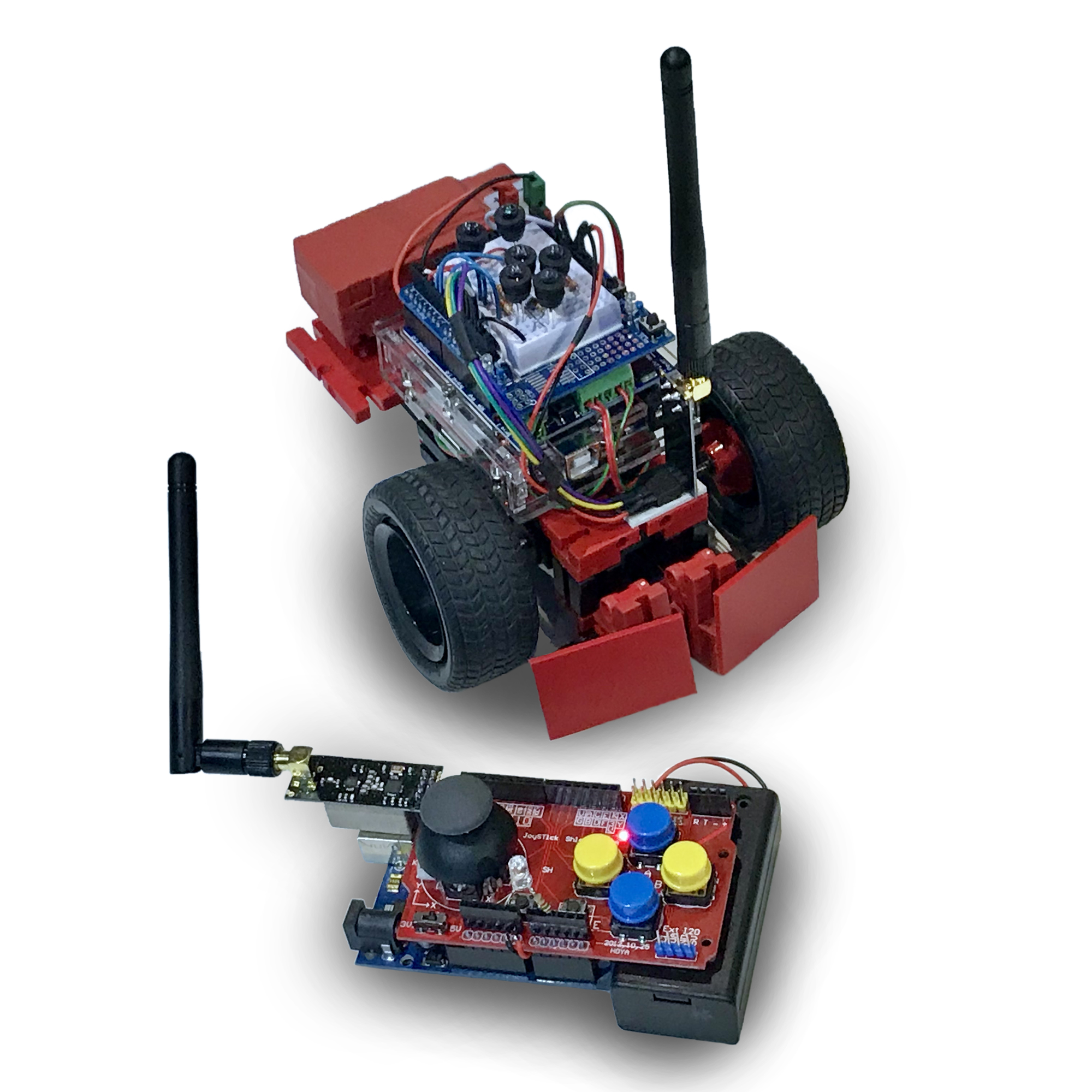
My first experiment with the joystick shield was to use it to radio control a smal buggy. And because the shield already features an interface for the nRF24L01 transceiver module, this seemed an obvious first thing to try.
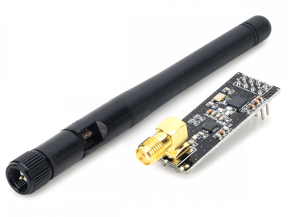
The nRF24L0+ transceiver module can often be obtained online for less than two dollars, and it seemed one of the most inexpensive bidirectional data communication options that you could get. According to the specs you’ll be able to communicate over a distance of 100 meters. Although that's more than enough for my simple experiments, I got greedy and aimed for the model with an external antenna, Power Amplifier (PA) and Low-Noise Amplifier (LNA) that is able to achieve a significantly larger transmission range of about 1000m.
The nRF24L01+ transceiver module is designed to operate in 2.4 GHz worldwide ISM frequency band and uses GFSK modulation for data transmission. The data transfer rate can be one of 250kbps, 1Mbps and 2Mbps. For my test, 250kbps seemed more than enough.
It is a 'transceiver', so the module can work as a transmitter, but also as a receiver. This makes it relatively easy to set up a very reliable and simple wireless communication over the SPI buses of two Arduinos with two of these modules. This connection can be seen from the software as a modem connection. If you're in for an in depth read, check the datasheet or this clear description.
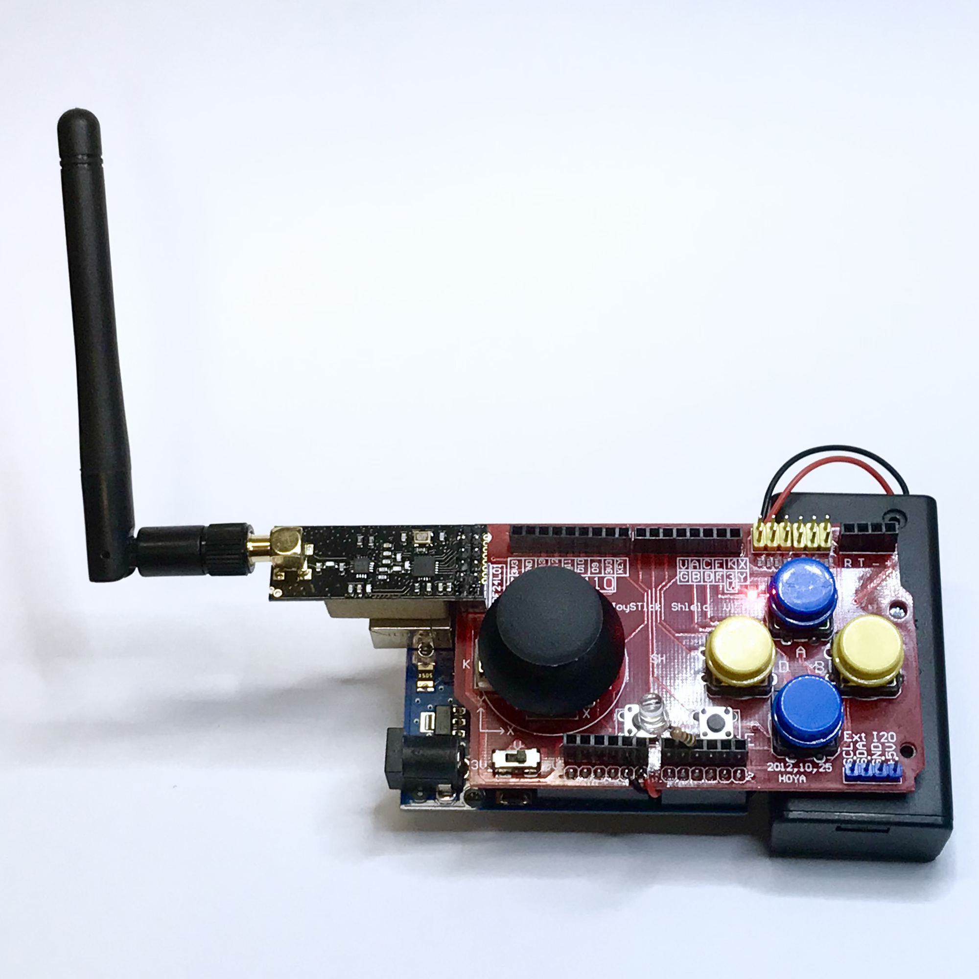
By equipping the joystick shield with an nRF24L01+ PA/LNA transceiver module, and some fiddling around with the available configuration options from the software, I managed to make a reliable handheld transmitter relatively quickly. As you can see in the picture (and in the video), I have not yet bothered to make a nice casing for it.
The power is supplied with a 9V battery in a compartment with an on / off switch. This is attached to the bottom of the print with Velcro. I have made a small support block to give the transceiver module some fysical support from the USB terminal. For an nRF24L01+ module without the antenna this may be an unnecessary overkill.
// Arnoud, last day of 2020 and further :-)
// Based on 'Arduino Joystick shield Code': https://maker.pro/arduino/projects/funduino-arduino-joystick-shield-controlled-robot
//
#include "nRF24L01.h"
#include "RF24.h"
#include "SPI.h"

#define DEBUG

#define CE_PIN  9
#define CSN_PIN 10

#define RECEIVE_LED A2 // Proof of concept to show receiving on the transmitter gamepad

#define button_A  2 // Button Blue - A
#define button_B  3 // Button Yellow - B
#define button_C  4 // Button Blue - C
#define button_D  5 // Button Yellow - D
#define button_E  7 // SMD button E on pcb
#define button_F  6 // SMD button F on pcb
#define button_joystick 8 // Button in joystick
#define x_axis A0
#define y_axis A1
int buttons[]={ button_A, button_B, button_C, button_D, button_E, button_F, button_joystick };

byte address[][6] = {"pipe1", "pipe2"}; // Set addresses of the 2 pipes for read and write
RF24 radio(CE_PIN,CSN_PIN);
int joystick[9]; // Array holding state of buttons and joystick X- and Y-reading
int received_value; // Value retreived from the other side...

void setup(){
  for (int i=0; i <7 ; i++) {
    pinMode(buttons[i], INPUT_PULLUP);
    digitalWrite(buttons[i], HIGH);
  }
  pinMode(RECEIVE_LED, OUTPUT);
  analogWrite(RECEIVE_LED, 0);

#ifdef DEBUG
  Serial.begin(115200);
#endif

  // Setup nRF240...
  radio.begin();
  radio.openWritingPipe(address[0]); // Open writing pipe to address pipe 1
  radio.openReadingPipe(1, address[1]); // Open reading pipe from address pipe 2
  radio.setDataRate(RF24_250KBPS);
  radio.setPALevel(RF24_PA_MIN); // Set RF power output to minimum: RF24_PA_MIN (change to RF24_PA_MAX if required)
  radio.setRetries(3,5); // delay, count
  radio.setChannel(110); // Set frequency to channel 110
}

void loop(){
  // Read digital buttons...
  for (int i=0; i <7 ; i++)
    joystick[i] = digitalRead(buttons[i]);

  // Read joystick values...
  joystick[7] = analogRead(x_axis);
  joystick[8] = analogRead(y_axis);

  // Write out values array...
  radio.write(joystick, sizeof(joystick));
  delay(20);

#ifdef DEBUG
  // Log...
  for (int i=0; i <9 ; i++) {
    Serial.print(joystick[i]);
    if (i<8)
      Serial.print(", ");
  }
  Serial.print("\n");
#endif

  radio.startListening();
  if (radio.available()) { // Get remote transmission
    radio.read(&received_value, sizeof(received_value));
    if (received_value>10) {
      analogWrite(RECEIVE_LED, 255);
#ifdef DEBUG
      Serial.print("received_value=");
      Serial.println(received_value);
#endif
    }
  } else
    analogWrite(RECEIVE_LED, 0);
  delay(20);
  radio.stopListening();
}
Both Sketches use the RF24 library for Arduino. Output A2 is used to drive the 'RECEIVE_LED' which can be switched on from the receiver to test the full duplex nature of the connection. Two 'channels' named "pipe1" and "pipe2" are set up which can be active alternately.
The values of the seven push buttons (four large, two smd type and the switch under the joystick) are put in an array. The last two values of the array are the X and Y value of the joystick, which can be between 0 and 1023.
Data communication with the RF24 radio is in bytes, so it can in principle be more economical, especially for communicating the binary button values. If you want to optimize things even further, you could even combine all these states in one byte.
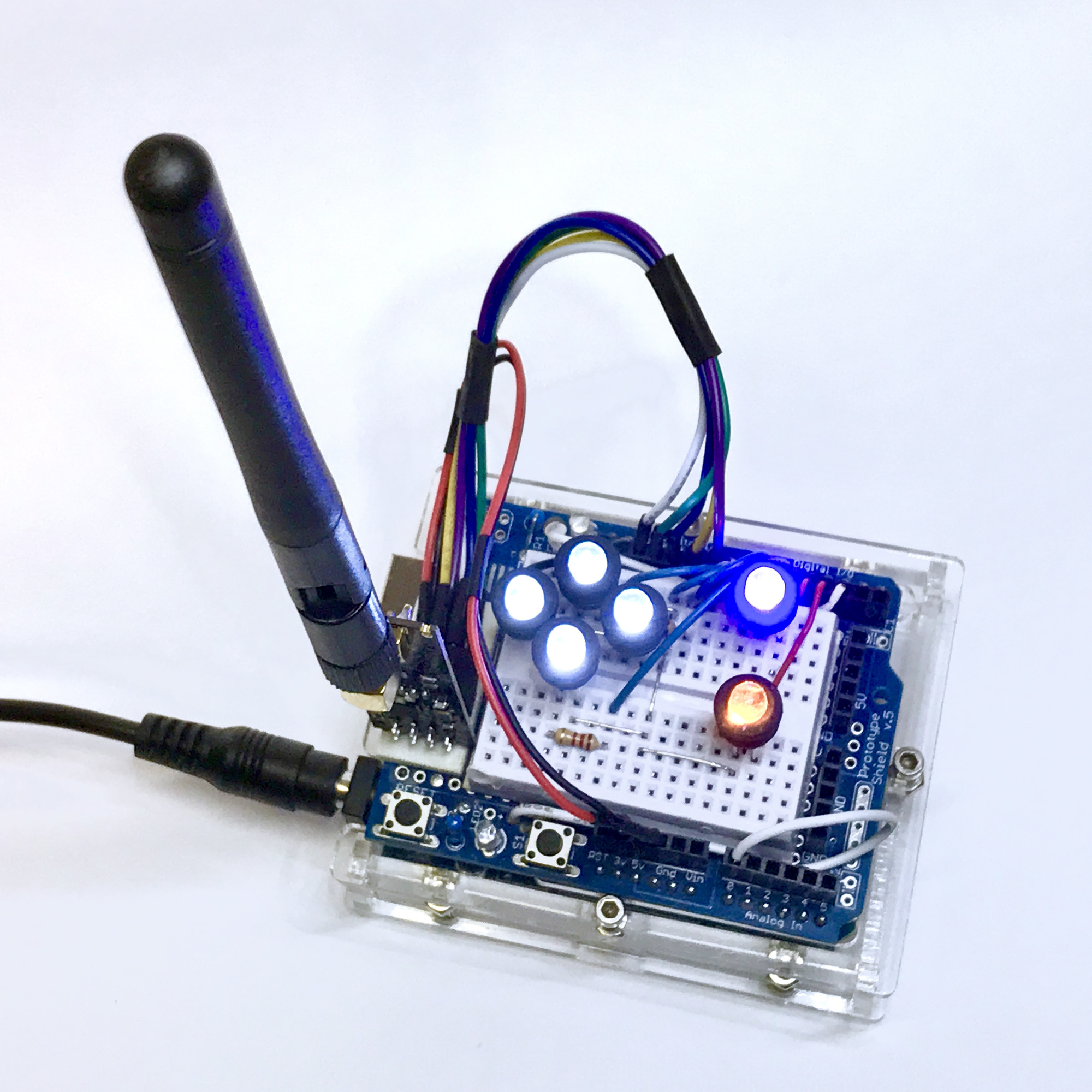
On the receiving side I equipped an Arduino Uno with a prototype shield so that I could accomodate some LEDs to test the connection and the sent commands from the joystick shield.
The possibilities that arise when two or more Arduino boards can communicate with each other wirelessly over a distance seemed very interesting to me. It will then be possible to monitor sensor data remotely, to control robots and to have them send back data, etc. As a test, I therefore used the switch on the prototype shield to return a signal and make the LED on the joystick shield light up. This proof of concept (communication back) has also been successful.
Of course these are not really useful functions yet, but that was not the intention for now either. To make things less theoretical however, I went a step further and made the joystick functional for driving the buggy.
// Arnoud, last day of 2020 and first week of 2021 :-)
// Based on 'Arduino Car Code': https://maker.pro/arduino/projects/funduino-arduino-joystick-shield-controlled-robot
//
// Connect motors (Adafruit Motor Shield):
//    Left Motor: MotorL (M1)
//    Right Motor: MotorR (M2)

#include "nRF24L01.h"
#include "RF24.h"
#include "RF24_config.h"
#include "SPI.h"
#include "Adafruit_MotorShield.h"

#define DEBUG // Outcomment for stealth/live operation...

// nRF24L01 defines...
#define CE_PIN  9
#define CSN_PIN 10

// Various defines...
#define LED_A 8  // Button A
#define LED_B 7  // Button B
#define LED_C 6  // Button C
#define LED_D 5  // Button D
#define LED_E 3  // Button E
#define LED_F 4  // Button F
#define LED_K 2  // Joystick button
#define SEND_BUTTON A1 // Switch to test talking back to joystick shield...
#define MaxSpeed 255   // Max motor speed
#define safeRange 50   // Safe range to ignore round midpoint of joystick readings...
#define Baudrate 115200

int leds[] = { LED_A, LED_B, LED_C, LED_D, LED_E, LED_F, LED_K };
int sendbutton;
int joystick[9]; // Communications array holding state of buttons and joystick X- and Y-reading
byte address[][6] = {"pipe1", "pipe2"}; // Set addresses of the 2 pipes for read and write
int dirMotorL = FORWARD;
int dirMotorR = FORWARD;
int motorSpeedL = 0;
int motorSpeedR = 0;
int speedDiff = 0;

RF24 radio(CE_PIN,CSN_PIN);
Adafruit_MotorShield MShield = Adafruit_MotorShield(0x60);
Adafruit_DCMotor *MotorL = MShield.getMotor(1); // Left motor
Adafruit_DCMotor *MotorR = MShield.getMotor(2); // Right motor

void buggycontrol() { // Control the Buggy
  // Show feedback with LEDs and log to serial during debug...
  for (int i=0; i <9 ; i++) {
    if (i<7) {
     if (joystick[i]==1)
       digitalWrite(leds[i], LOW);
     else
       digitalWrite(leds[i], HIGH);
    }
#ifdef DEBUG
    Serial.print(joystick[i]);
    if (i<8)
      Serial.print(", ");
#endif
  }
#ifdef DEBUG
  Serial.print("\n");
#endif

  // Determine (signed/directional) speed based on Y-axis joystick value reading,
  // ignore range around midpoint (theoretically 512) to prevent unwanted jitter...
  motorSpeedL = motorSpeedR = 0;
  if (joystick[8] < 512-safeRange) {
    motorSpeedL = map(joystick[8], 0, 512, -MaxSpeed, 0);
    motorSpeedR = motorSpeedL;
  } else if (joystick[8] > 512+safeRange) {
      motorSpeedL = map(joystick[8], 512, 1023, 0, MaxSpeed);
      motorSpeedR = motorSpeedL;
  }

  // Determine relative (signed/directional) curve-/turn-speed difference based on X-axis reading,
  // ignore range around midpoint (theoretically 512) to prevent unwanted jitter...
  speedDiff = 0;
  if (joystick[7] < 512-safeRange) {
    speedDiff = map(joystick[7], 0, 512, -255, 0);
  } else if (joystick[7] > 512+safeRange) {
      speedDiff = map(joystick[7], 512, 1023, 0, 255);
  }
  motorSpeedL = (motorSpeedL+speedDiff);
  motorSpeedR = (motorSpeedR-speedDiff);

  // Determine direction per motor...
  dirMotorL = FORWARD;
  dirMotorR = FORWARD;
  if (motorSpeedL<0) dirMotorL = BACKWARD; // Reverse...
  if (motorSpeedR<0) dirMotorR = BACKWARD; // Reverse...

  // Crop and absolutize motorspeeds...
  motorSpeedL = abs(motorSpeedL);
  motorSpeedR = abs(motorSpeedR);
  if (motorSpeedL>MaxSpeed) motorSpeedL = MaxSpeed;
  if (motorSpeedR>MaxSpeed) motorSpeedR = MaxSpeed;

#ifdef DEBUG
  Serial.print("\nmotorSpeedL = ");
  Serial.print(motorSpeedL);
  Serial.print(", motorSpeedR = ");
  Serial.print(motorSpeedR);
  Serial.print(", speedDiff = ");
  Serial.print(speedDiff);
  Serial.print(", dirMotorL=");
  Serial.print(dirMotorL);
  Serial.print(", dirMotorR=");
  Serial.print(dirMotorR);
  Serial.print("\n");
#endif

  MotorL->run(dirMotorL);
  MotorR->run(dirMotorR);
  MotorL->setSpeed(motorSpeedL);
  MotorR->setSpeed(motorSpeedR);
}

void setup() {
#ifdef DEBUG
  Serial.begin(Baudrate); // Start serial monitor...
#endif

  // Setup LEDs...
  pinMode(LED_A, OUTPUT);
  pinMode(LED_B, OUTPUT);
  pinMode(LED_C, OUTPUT);
  pinMode(LED_D, OUTPUT);
  pinMode(LED_E, OUTPUT);
  pinMode(LED_F, OUTPUT);
  pinMode(LED_K, OUTPUT);
  pinMode(SEND_BUTTON, INPUT_PULLUP);

  MShield.begin(); // Motor Shield initialize...
  Wire.setClock(400000); // Set I²C-Frequenz at 400 kHz

  // Initialize motors...
  MotorL->setSpeed(motorSpeedL);
  MotorR->setSpeed(motorSpeedR);

  // Setup nRF24L01 communication...
#ifdef DEBUG
    Serial.println("nRF24L01 setup");
#endif

  // Blink that we're alive: all LEDs on...
  digitalWrite(LED_A, HIGH);
  digitalWrite(LED_B, HIGH);
  digitalWrite(LED_C, HIGH);
  digitalWrite(LED_D, HIGH);
  digitalWrite(LED_E, HIGH);
  digitalWrite(LED_F, HIGH);
  digitalWrite(LED_K, HIGH);

  radio.begin();
  radio.openReadingPipe(1, address[0]); // Open reading pipe from address pipe 1
  radio.openWritingPipe(address[1]); // Open writing pipe to address pipe 2
  radio.setDataRate(RF24_250KBPS);
  radio.setPALevel(RF24_PA_MIN); // Set RF power output to minimum: RF24_PA_MIN (change to RF24_PA_MAX if required)
  radio.setRetries(3,5); // delay, count
  radio.setChannel(110); // Set frequency to channel 110

  delay(2000); // Signal power-up...

  // Blink: all LEDs off...
  digitalWrite(LED_A, LOW);
  digitalWrite(LED_B, LOW);
  digitalWrite(LED_C, LOW);
  digitalWrite(LED_D, LOW);
  digitalWrite(LED_E, LOW);
  digitalWrite(LED_F, LOW);
  digitalWrite(LED_K, LOW);

  radio.startListening();
}

void loop() {
  if (radio.available()) { // Get remote transmission
    radio.read(joystick, sizeof(joystick));
    buggycontrol(); // Control the Buggy...
  }

  sendbutton = analogRead(SEND_BUTTON);
  if (sendbutton<100) {
    radio.stopListening();
    radio.write(&sendbutton, sizeof(sendbutton)); // Send state to other Arduino board
#ifdef DEBUG
    Serial.print("SEND_BUTTON=");
    Serial.println(sendbutton);
#endif
    radio.startListening();
  }
}
I used the Buggy as a practical example of useful remote control. Earlier I had made it controllable with an infrared remote control, but since the joystick control is much more precise and analog, the software for controlling both motors had to be rewritten.
The x-axis joystick controls the difference in running speed between both motors. Because the directional difference is thus superimposed in this way, it is now possible to make very precise turns at any speed or direction. This also makes it possible to let the buggy twist in place without any forward speed. Both motors then run at the same speed, but in opposite directions.
Because a motor shield was used in the Buggy, I have drawn the connections to it below. Naturally, the nRF24L01 can also be connected directly to the corresponding ports of an Arduino Uno without a motor shield.
The whole invites further experimentation. For example, I will certainly investigate the possibilities of Bluetooth and controlling a small display on the joystick shield (with, for example, sensor data from the controlled model).
Perhaps it may be worthwhile to make a more robust casing from, for example, a few sheets of plexiglass. But even now, the joystick shield is very useful to easily add game control or manual robot control type functionality to a project. For most controls, one joystick and a few additional switches are more than enough.
After some unsuccessful experiments, communication with the nRF24L01 module turned out to be set up quite easily. I found however few solid programming examples of the bidirectional communication. The Arduino Sketches I made can be found here for download. Notify me of your own improvements and have fun!