
With the mechanically constructed gearbox, the ratios between rotational speeds simply follow from the gear ratios of the gear into which the gearbox is switched. But it is useful to know what the ground speed (in revolutions per minute; rpm) is at any given time.
I started experimenting with IR obstacle sensors to measure small reflective stripes on the wheels. My rpm meter directly measures several sensors and can also display the (approximate) ratio directly on an LCD screen.
With a mechanical gearbox, various derived rotational speeds can be made from one incoming motor drive. Since only one motor is used, the ratios of rotational speeds simply follow the gear ratios.
With electronic control, however, two separate motors are required. Insight into the precise final turning speeds and ratios then becomes more difficult. Differences in the pulse widths of the control or the friction or play in the mechanical construction all play a role. Because both movements do not originate from one source, the final individual rotational speeds are influenced both electronically and mechanically.
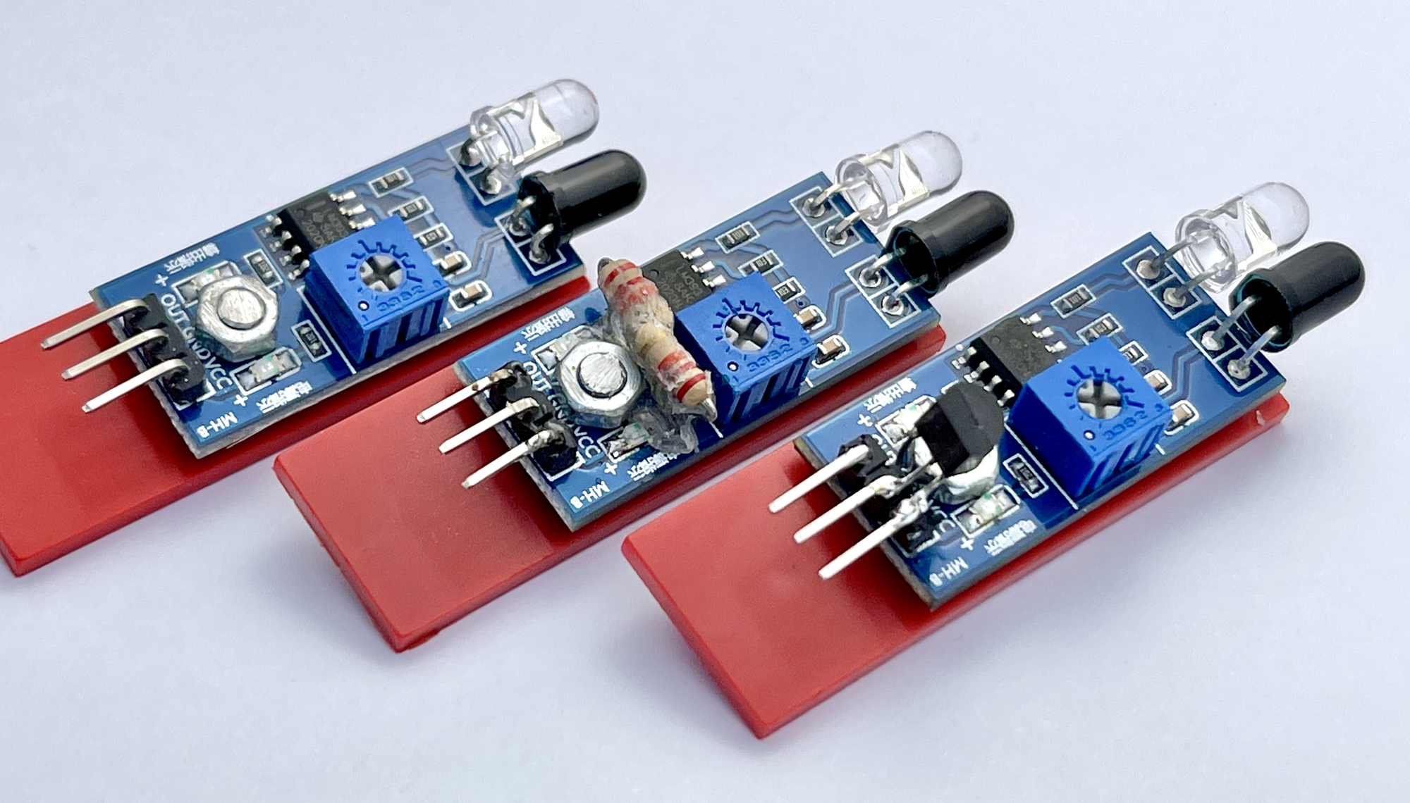
For measuring the rotational speed I came across some principles online. Some used the IR sensors that had already been used in a former project for this.
I found some examples online, but none of them were sufficient for relatively low speeds. In addition, they could measure only one rotational speed without exception and therefore lacked a mode in which the ratio between two speeds is displayed anyway.
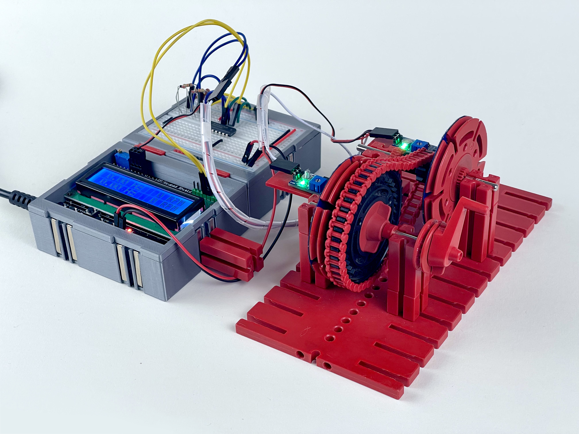
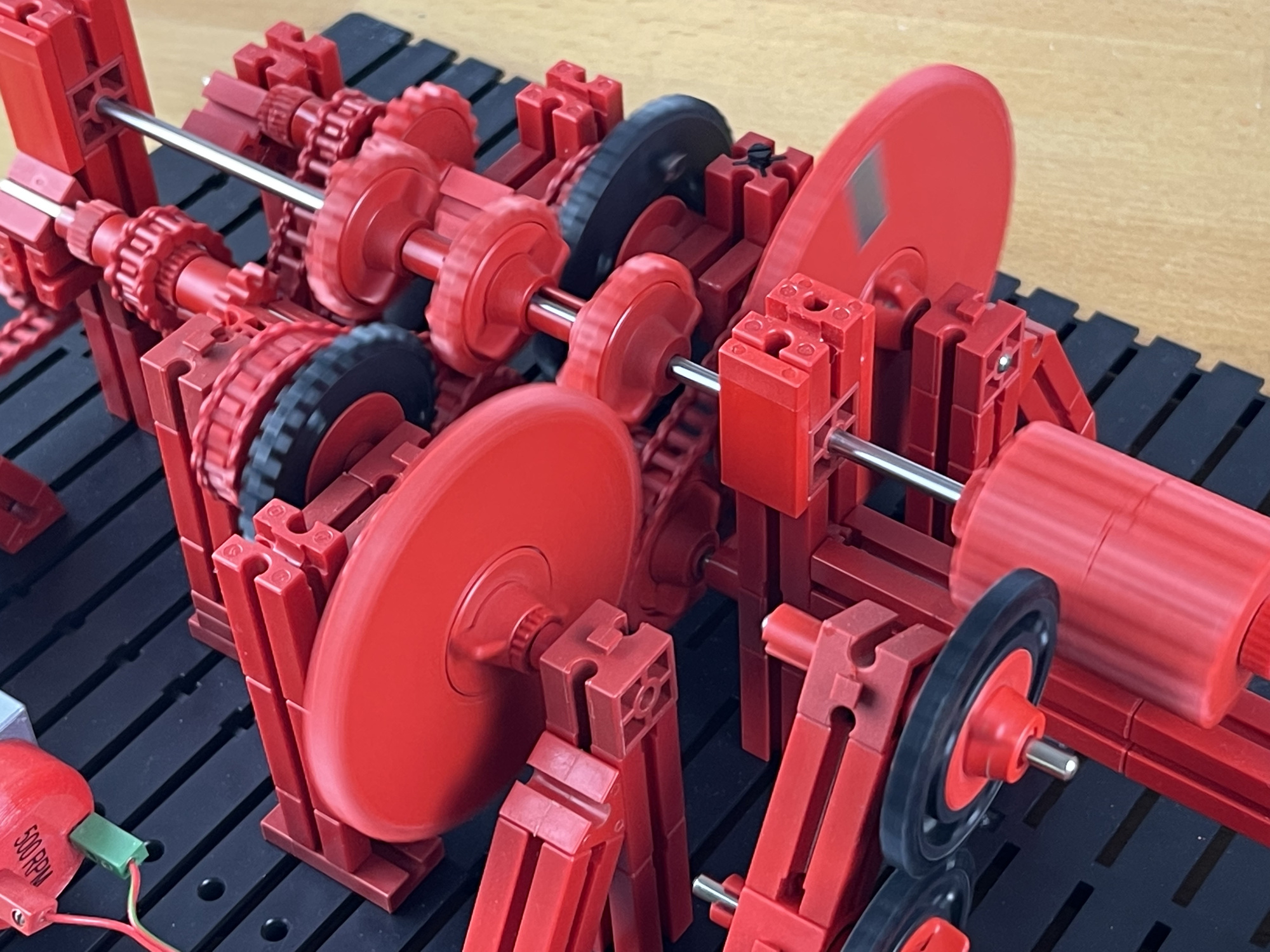
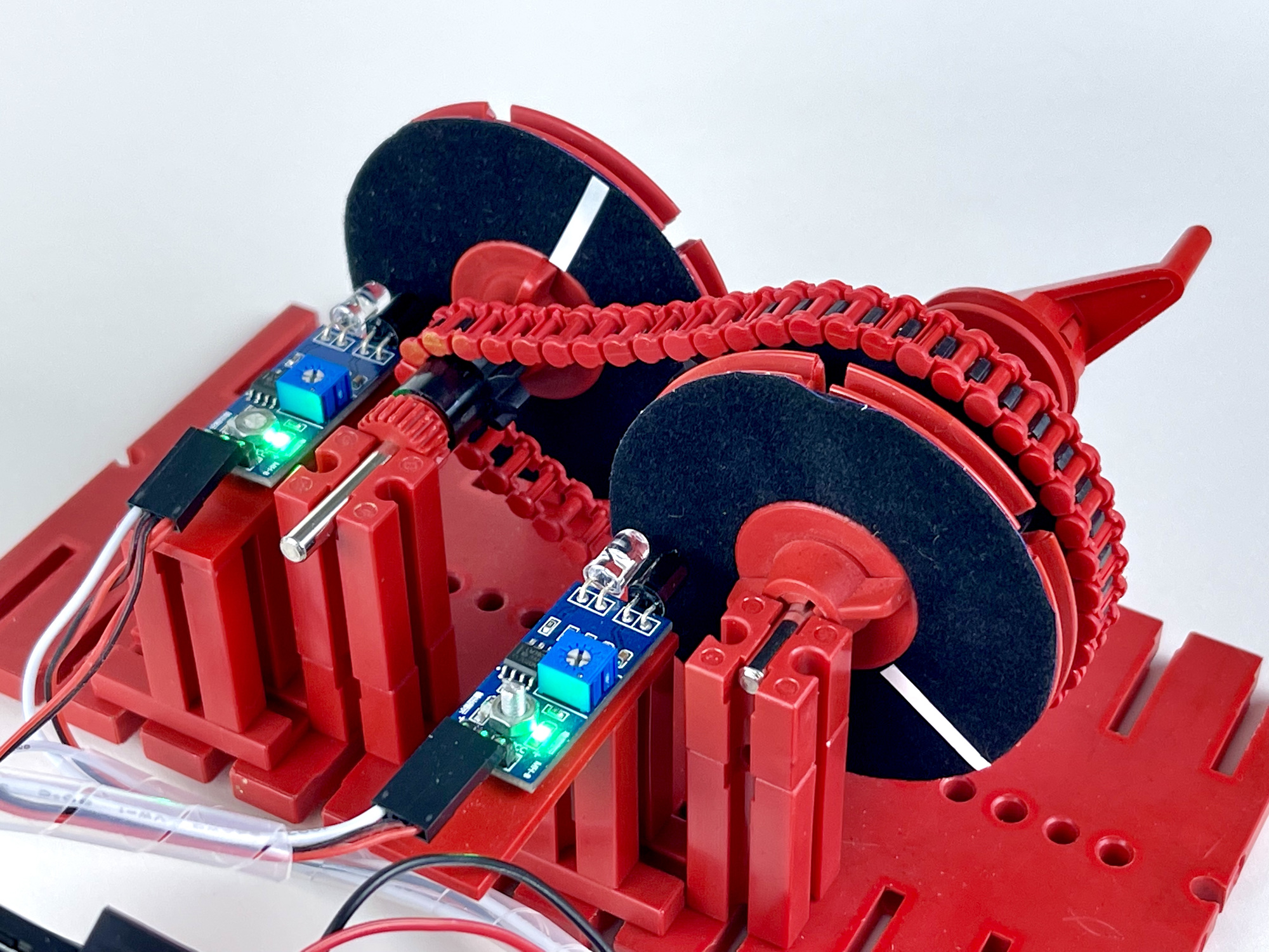
I preferred to use a universal Arduino Uno with LCD Keypad Shield. Because this microcontroller has two hardware interrupts, it would be possible to measure two speeds at once. The IR obstacle sensors can be adjusted to be triggered by a passing reflective strip on the wheel whose rotational speed is to be measured. As shown in the picture of the gearbox opposite, I already stuck a strip on the largest sprocket on which the basic rotational speed of the gearbox could be measured.
The idea would be to have this pulse edge trigger a hardware interrupt from the Arduino. This has the advantage that the measurement is independent of the delay in the main loop of the program that controls the display, among other things.
However, it soon became clear that the detection edge of such optical measurements absolutely cannot be used to trigger an interrupt on the Arduino. As shown in the adjacent image (yellow top curve), at a lower rotational speed it can quickly go towards 1 ms. Such an edge simply immediately triggers dozens of interrupts!
Therefore I buffered (and inverted) the sensor signal with a so-called Schmitt inverter. This 'flips around' at one point and makes the pulse edge nice and sharp again. See the bottom green pulse. Now a passing reflective dash on the wheel produced only one interrupt each time.
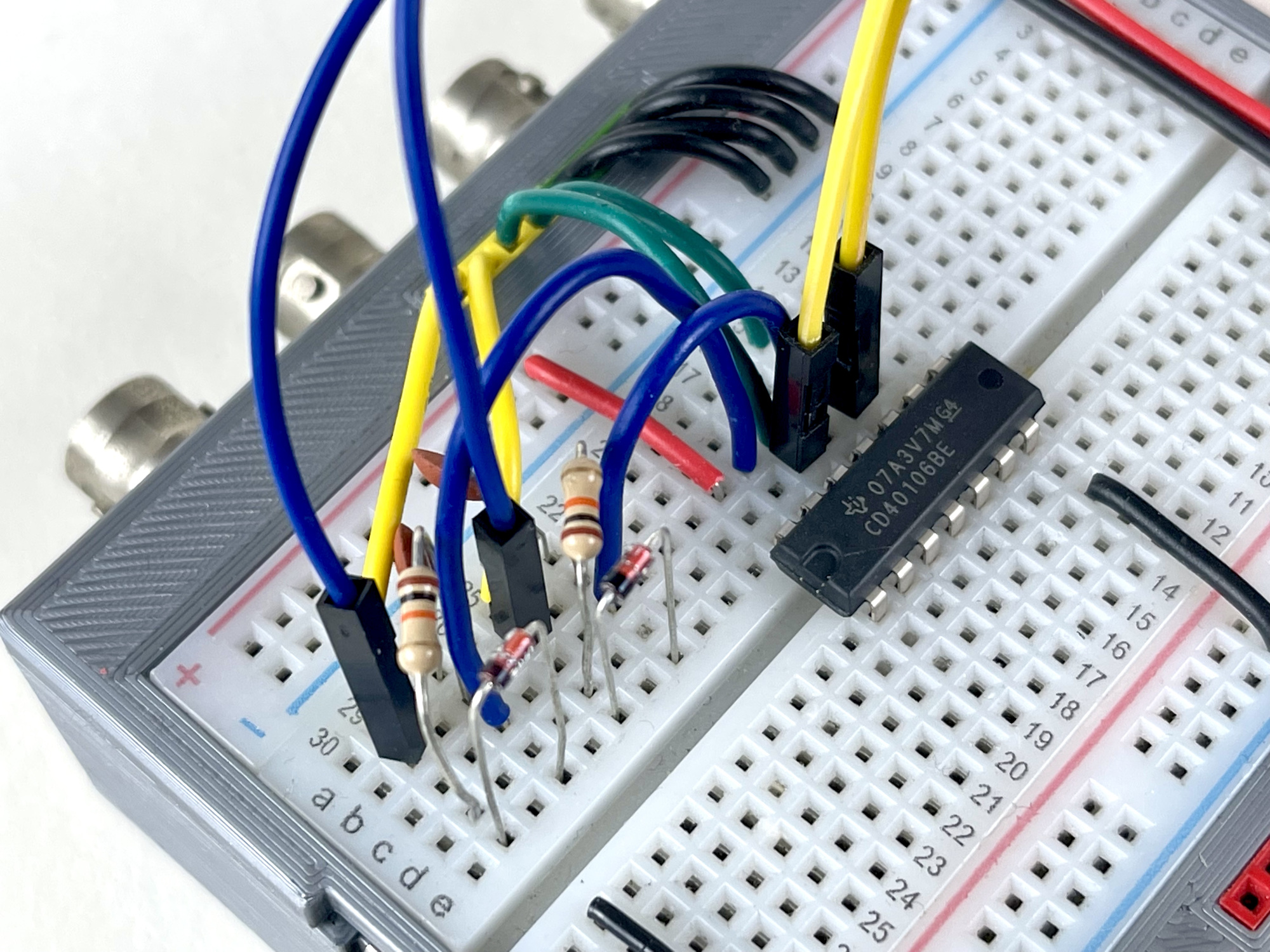
The photos show the experimental set-up with two test sensors. Because the used Schmitt IC (CD40106) contains six inverters, it seems sensible to make a separate module so that the pulses from these sensors can also be used more flexibly in the future as inputs for flip-flops, counters or other discrete digital logic for which steep (clock) pulses are indispensable.
Because the pulses are then polished close to 'processing', the influence of lead capacitance, crosstalk and sensor leads impedance is reduced as well. This certainly improves the precision of the measurements.
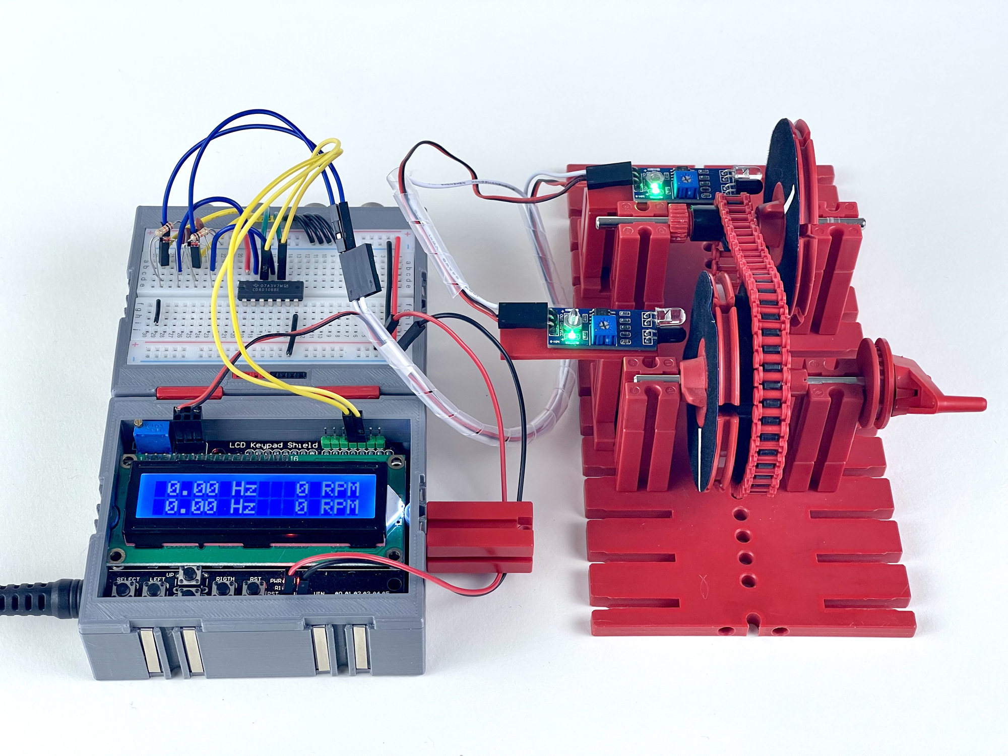
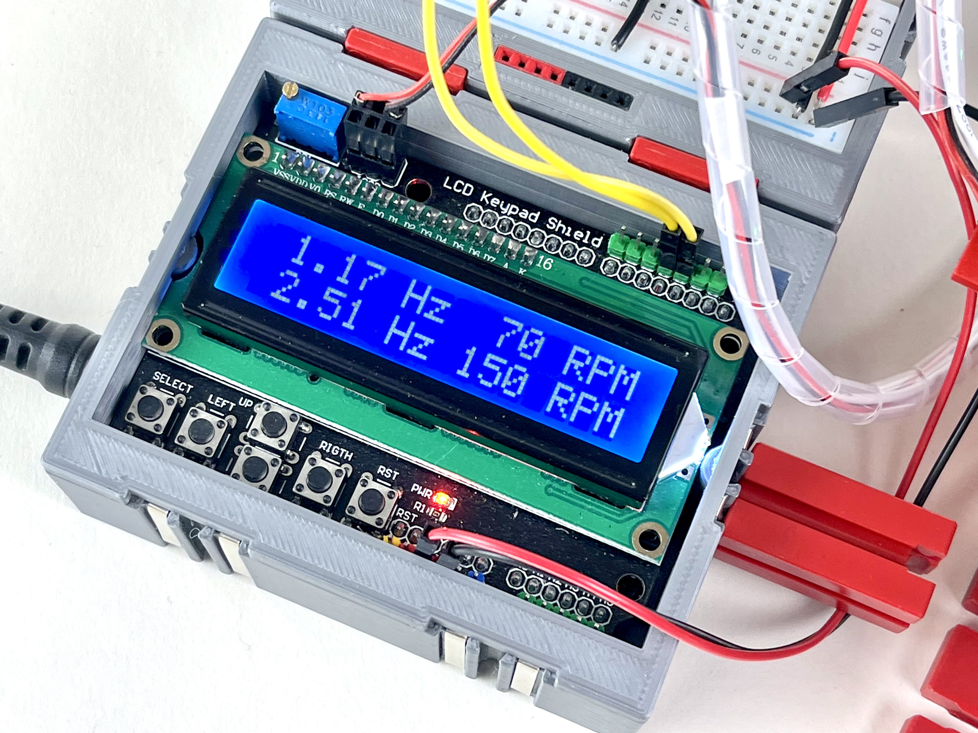
On the right (the first version of) the Sketch that I wrote to read two sensors. It is based on an Arduino Uno on which the LCD Keypad Shield is mounted. The sensor outputs are connected to P2 and P3. I take the 5 volt supply voltage for the sensors from the ICSP connector of the shield.
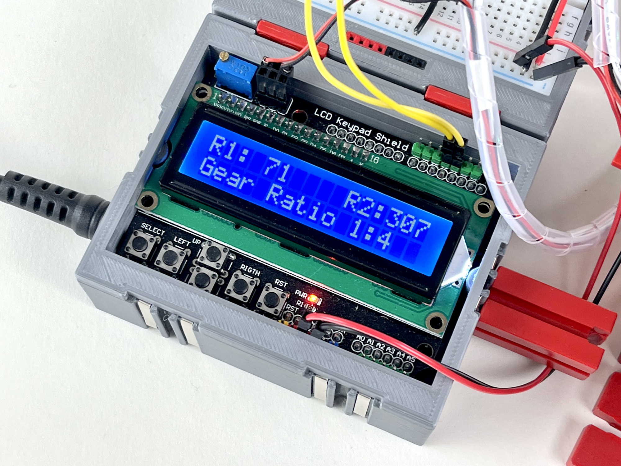
The display lighting can be switched off and on again with the 'Select' button. With the 'Right' button (called 'Rigth' on my cheap Chinese clone, haha) the display mode can be switched between Hz/rpm and the gear ratio between the two rotational speeds.
// Simple dual freq/RPM meter with IR-obstacle detectors - WhizzBizz.com Arnoud van Delden 9th feb 2023
// Buttons reading based on sketch at https://www.elecrow.com/wiki/index.php?title=LCD_Keypad_Shield
// Interrupt stuff on https://projecthub.arduino.cc/BEASTIDREES62/d4a796a9-5bdf-4d5e-96ae-cd7fce0a4dc7

//Sample using LiquidCrystal library
#include

// select the pins used on the LCD panel
LiquidCrystal lcd(8, 9, 4, 5, 6, 7);

// define some values used by the panel and buttons
int lcd_key     = 0;
int adc_key_in  = 0;
#define btnRIGHT  0
#define btnUP     1
#define btnDOWN   2
#define btnLEFT   3
#define btnSELECT 4
#define btnNONE   5
#define BACKLIT   10
#define SENS1SIG  2
#define SENS2SIG  3
#define DISPL_UPD 1000 // Every x ms...

bool backlitOn = true;
bool rpmFactorMode = false; // Display mode toggle...
volatile unsigned long difftime;
volatile bool tooslow = 1;
unsigned long lastdisplay;
float factor;

// Rpm1
volatile unsigned long lasttime1;
volatile unsigned long rpmtime1;
float period1;
float hrz1;
unsigned int rpm1;

// Rpm2
volatile unsigned long lasttime2;
volatile unsigned long rpmtime2;
float period2;
float hrz2;
unsigned int rpm2;

// Display output...
char lcd_line0[17]; // Line buffers for LCD
char lcd_line1[17];

// read the buttons
int read_LCD_buttons() {
  adc_key_in = analogRead(0);      // read the value from the sensor
  // Serial.print("Key value: ");
  // Serial.println(adc_key_in);

  // Button values of my perticulair board: 0, 135, 313, 486, 725
  // we add approx 50 to those values and check to see if we are close
  if (adc_key_in > 1000) return btnNONE; // We make this the 1st option for speed reasons since it will be the most likely result
  if (adc_key_in < 50)   return btnRIGHT;
  if (adc_key_in < 150)  return btnUP;
  if (adc_key_in < 350)  return btnDOWN;
  if (adc_key_in < 500)  return btnLEFT;
  if (adc_key_in < 750)  return btnSELECT;
  return btnNONE;  // when all others fail, return this...
}

void setup() {
  Serial.begin (115200);
  pinMode (BACKLIT,OUTPUT); // Display backlit...

  lcd.begin(16, 2);              // start the library
  lcd.setCursor(0,0);

  // Set up timers and interrupts for sensor inputs...
  TCCR1A = 0;
  TCCR1B = 0;
  TCCR1B |= (1 << CS12);  // Prescaler 256
  TIMSK1 |= (1 << TOIE1); // Enable timer overflow
  pinMode (SENS1SIG, INPUT_PULLUP);
  attachInterrupt(0, RPM1, FALLING);
  pinMode (SENS2SIG, INPUT_PULLUP);
  attachInterrupt(1, RPM2, FALLING);
  //oneSecond = millis();
}

void loop() {
  if (millis()-lastdisplay>DISPL_UPD) {
    updateDisplay();
    lastdisplay = millis();
  }

  // Read buttons...
  lcd_key = read_LCD_buttons();  // read the buttons
  //lcd.setCursor(0,1);          // move to the begining of the second line
  switch (lcd_key) {             // depending on which button was pushed, we perform an action
    case btnRIGHT:
      //lcd.print("RIGHT ");
      while (read_LCD_buttons()==btnRIGHT) delay(10); // Wait until released...
      rpmFactorMode = !rpmFactorMode; // Switch display mode...
      break;
    case btnLEFT:
      //lcd.print("LEFT   ");
      break;
    case btnUP:
      //lcd.print("UP    ");
      break;
    case btnDOWN:
      //lcd.print("DOWN  ");
      break;
    case btnSELECT: // Toggle backlit of LCD...
      //lcd.print("SELECT");
      while (read_LCD_buttons()==btnSELECT) delay(10); // Wait until released...
      backlitOn = !backlitOn;
      break;
    case btnNONE:
      //lcd.print("NONE  ");
      break;
  }

  if (backlitOn==true) {
    digitalWrite(BACKLIT, HIGH);
  } else {
    digitalWrite(BACKLIT, LOW);
  }

}

void updateDisplay() { // Update the display...
  if (tooslow) { // Flush values...
    hrz1 = 0;
    rpm1 = 0;
    hrz2 = 0;
    rpm2 = 0;
    factor = 0;
  } else { // Show calculated values...
    period1 = (rpmtime1 / 1000.00);
    hrz1 = (1 / period1);
    rpm1 = (60 * hrz1);
    period2 = (rpmtime2 / 1000.00);
    hrz2 = (1 / period2);
    rpm2 = (60 * hrz2);
    if (hrz1>0 && hrz2>0) {
      if (hrz1>hrz2)
        factor = hrz1/hrz2;
      else
        factor = hrz2/hrz1;
    } else
      factor = 0;
  }

  if (!rpmFactorMode) {
  // Trick to correctly print the float value using sprintf...
    sprintf(lcd_line0, "%2d.%02d Hz %3d RPM", (int)hrz1, (int)(hrz1*100)%100, rpm1);
    sprintf(lcd_line1, "%2d.%02d Hz %3d RPM", (int)hrz2, (int)(hrz2*100)%100, rpm2);
  } else {
    sprintf(lcd_line0, "R1:%3d    R2:%3d", rpm1, rpm2);
    if (factor>0)
      sprintf(lcd_line1, "Gear Ratio 1:%d  ", round(factor));
    else
      sprintf(lcd_line1, "Gear Ratio 1:?  ", round(factor));
  }

  // Write to display...
  lcd.setCursor(0,0);
  lcd.print(lcd_line0);
  lcd.setCursor(0,1);
  lcd.print(lcd_line1);
}

ISR(TIMER1_OVF_vect) {
  tooslow = 1; // No pulses received for ~1 sec...
}

void RPM1 () {
  difftime = millis()-lasttime1;
  rpmtime1 = difftime;
  lasttime1 = millis();
  tooslow = 0;
}

void RPM2 () {
  difftime = millis()-lasttime2;
  rpmtime2 = difftime;
  lasttime2 = millis();
  tooslow = 0;
}
The dual rpm and turning ratio meter will mainly be used in the next project to measure the basic turning speed. After all, with the mechanical gearbox, the ratio between the rotational speeds can be read directly as the selected 'gear'.
However, as soon as two separate motors are used, and these will have to be controlled individually with electronics, it will really be able to prove its worth. The readout mode in which the ratio between the two rotation speeds is immediately shown on the display is already built in... 😉 To be continued...