This article describes some common methods of back-and-forth and up-and-down movement. I try out some controls for an up and down elevator.
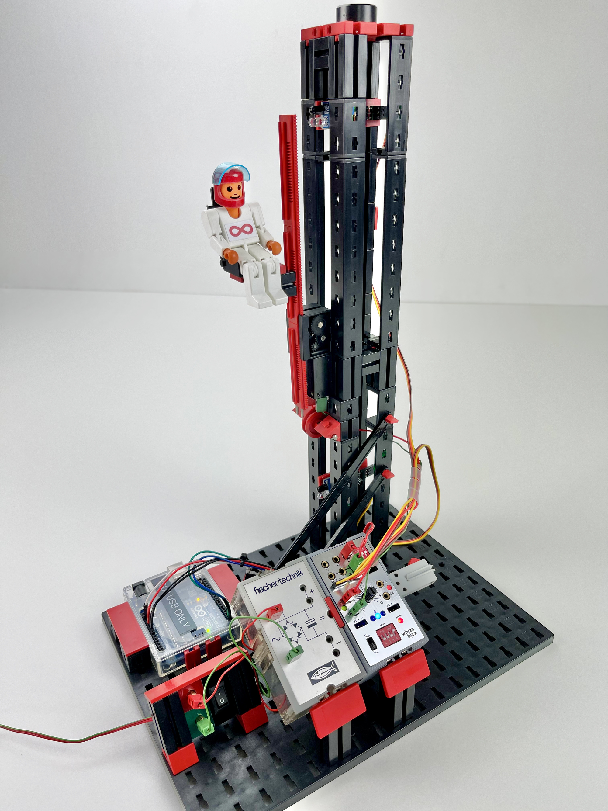
In a previous project I've built a small microcontroller for use with the traditional fischertechnik 'Silberlings' that enabled the use of infrared sensors in this elevator experiment. It was a good project to experiment with a gradual speed curve for the motor as well.
The newfangled magician is in the wings. The magic wand has been polished. The first spells have been learned. It is not perfect yet, but the great magic book can always be supplemented or improved upon. In a few seconds he will see a room full of old acquaintances with whom he can work. That's where the curtain goes. The time has come to show his magical arts!

A recurring challenge for the builder of moving fischertechnik models is the back-and-forth or up-and-down movement. A lift has to go up and down, a cart from left to right, a slide open and closed or a push bar from front to back. Although the use of a servo is the obvious choice for the smaller motion nowadays, for a larger stroke you cannot avoid the use of a mechanical construction or a motor that is reversed at the extremes.
Most ideal is a solution with contactless sensors in which the motor is not bluntly reversed at its extreme points, but the directional change is along smooth rotational speed curve. In this article I describe my quest and investigate the role the magic of the Zauberling could play in this.
A solution without any help from electronics is the pure mechanical movement. With an egg-wheel, acentrically rotating rod or crankshaft construction (cardan), a rotating motion can be converted into a linear one. This 'Straight stroke crank' principle is also nicely explained in the fischertechnik Hobby books, such as Hobby 1, volume 2 (German: 'Geradshub Kurbelgetriebe') on page 54. The movements of a sewing machine or jigsaw are good examples of this. When the moving rod drives another rod with a pivot point, a swinging movement is created, such as we know from our windshield wipers, for example. Those who are interested can find more background information in the 'Elemente der Technik' books in the library on the website of the Dutch fischertechnik club (Elementen der Technik - Part 1, page 15).
A purely mechanical method is reliable and simple. The speed around the 'turning point' of the sliding movement follows a gradual speed course. The movement at the extreme points of the movement is not abrupt or jerky. As a result, the inertia of the moving (sliding) part puts minimal stress on the construction. The rotation has a fixed speed and the motor can simply continue to rotate in one direction. And because it works without interference-prone contacts or sensors, no protections need to be built in to prevent the sliding movement from unexpectedly exceeding its limits and the construction 'twisting itself to pieces'.
For a mechanical method, however, relatively much auxiliary construction is required for transmissions, etc. Moreover, the installation space is relatively large compared to the relatively limited stroke of the sliding motion.
The simplest electromechanical solution is by using a reverse polarity switch. If the wiring has sufficient freedom of movement and the movement is relatively small, the polarity reversal switch can be mounted on the moving part of the structure. For longer trajectories, bump cams can alternately actuate the switch positioned along the trajectory. Another solution is to run a string attached to the moving element through the lever of the reversing switch, which operates the reversing switch with buttons in the right place.
Leds connected in opposite phase can light up directly alternately with the direction of movement as an indication without much additional wiring. Of course we can also achieve this behavior by using a few diodes in the connections of traditional light bulbs.
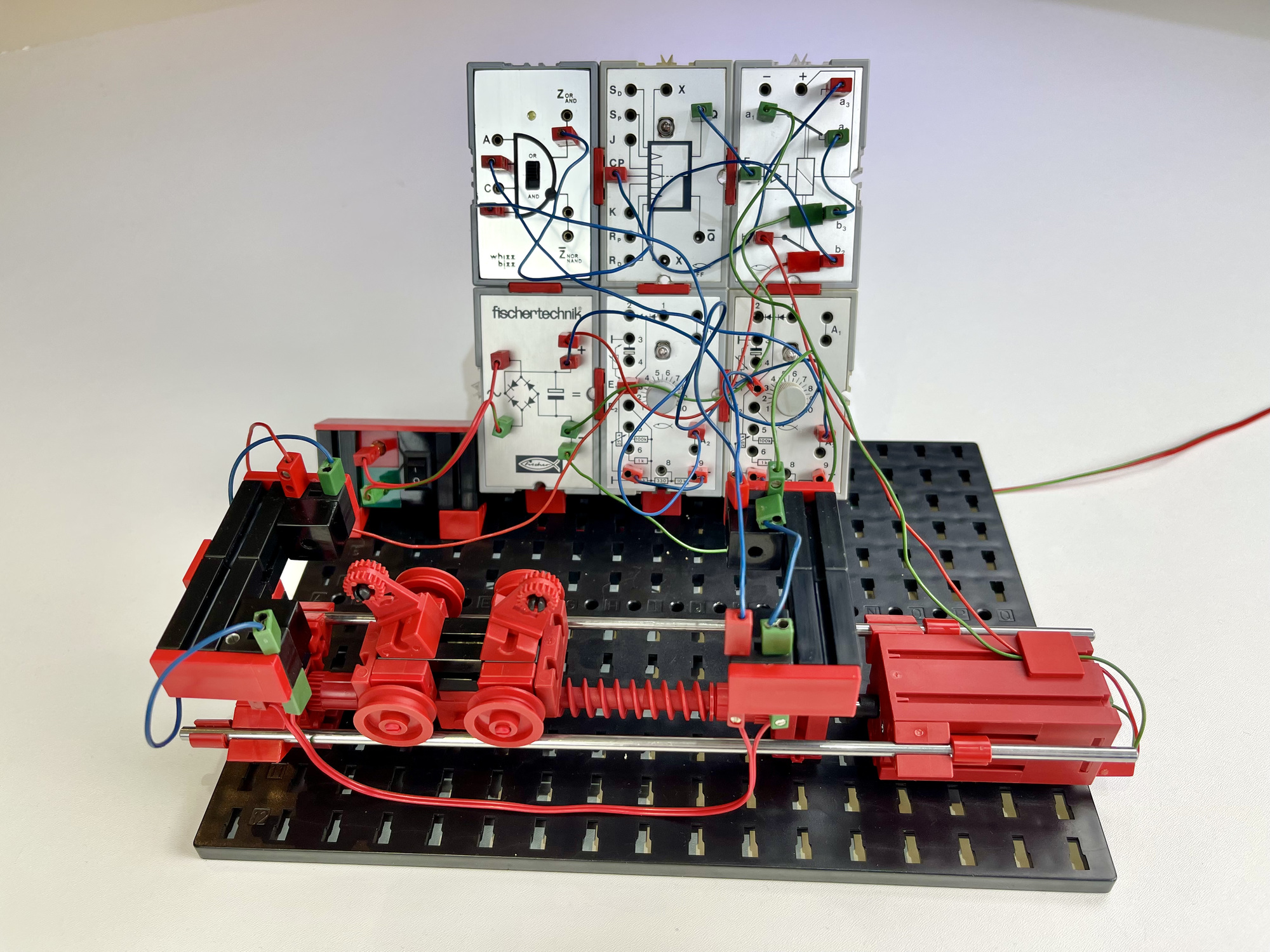
Those who are nostalgic can build the above solution with the traditional 'Silberlings' Flipflop h4 FF (30815) in which the relay module h4 RB (30812) always reverses the supply voltage of the motor. Switches (with 'suppressor' capacitors of 100nf, see Hobby 4 part 3 fig. 66.3 and 66.4) can be connected to the Flipflop pulse inputs in this way. For non-contact sensors, such as photoresistors or transistors, for which the detection threshold must be adjustable, these signals are routed via Grundbaustein (Electronics Basic Building Block) h4 G (30813). Theory and numerous building examples can be found in the booklet of the 'IC Digital Praktikum' or Hobby 4, Volume 3.
In this experiment, photo-resistors were used as limit sensors, but photo-transistors can of course also be used as light sensors. Another contactless way of end point detection is possible with a reed-contact.
With mechanical impulse switches or magnetic switches at the extreme points of the movement, an electronic solution can be created with the flip-flop Silberling. We can use the edge-sensitive inputs Sp and Rp for this. However, do not forget the interference suppression with a 100 nf capacitor against switching noise and spurious impulses that can occur with mechanical impulse switches.
When using non-contact sensors such as the photo-resistor or photo-transistor, the threshold detection can be set with the Grundbaustein. The two output signals of the Grundbausteinen can be connected to the Cp via an OR gate so that the sensors start to work as a toggle.
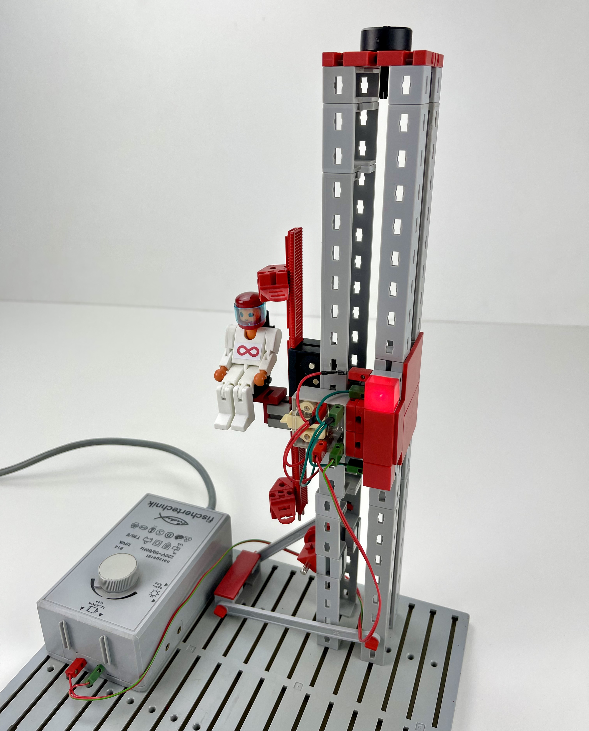
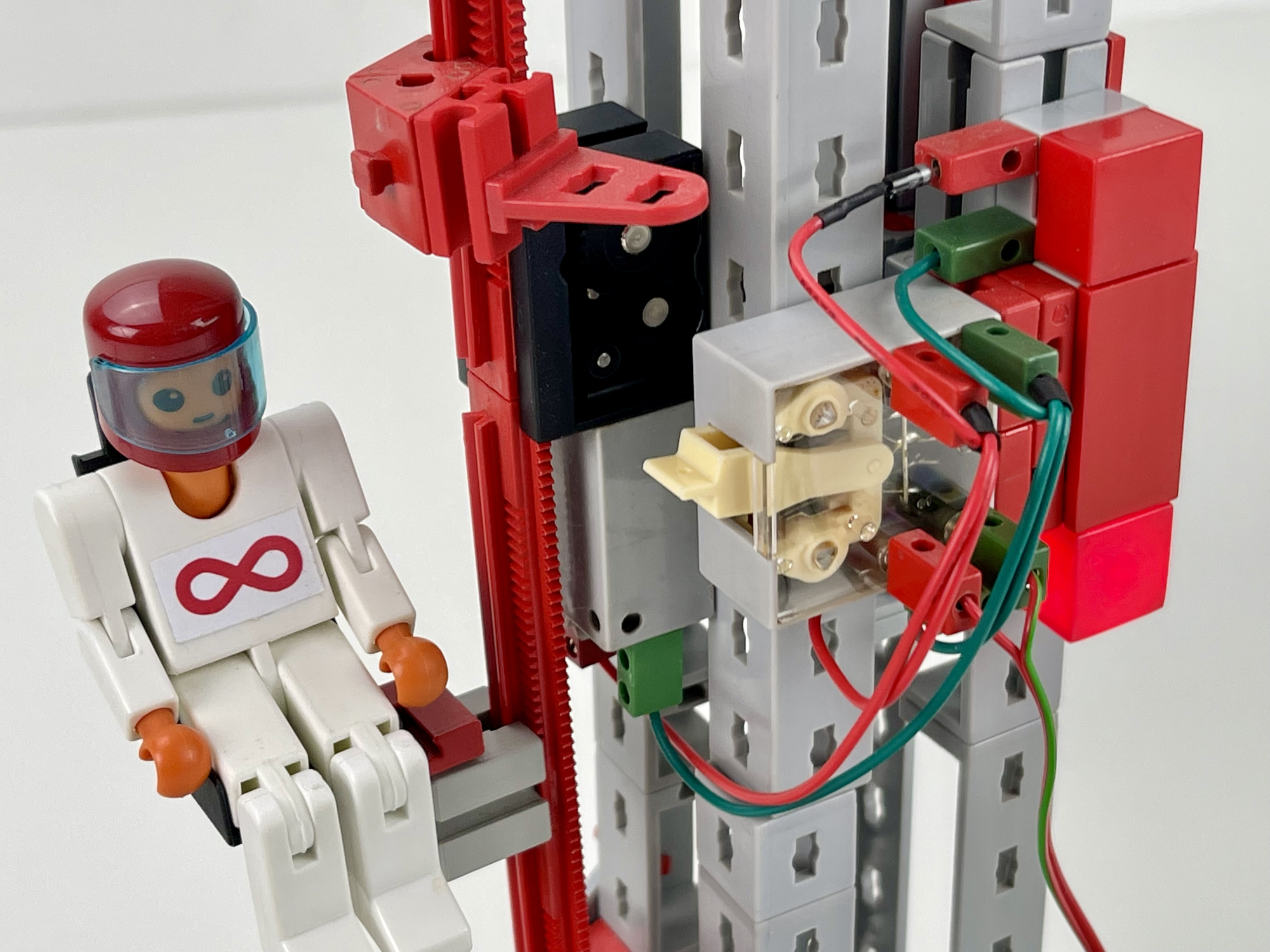
Instead of a light box, it seemed like a fun experiment to use two IR-obstacle sensors to detect the endpoints. These are 'active' sensors that require a supply voltage of 5 volts and output their supply voltage at the output when at rest. As soon as an object is detected within the distance that can be set on the module, this output voltage drops to zero. This is basically the same negative logic that the Silberlingen use.
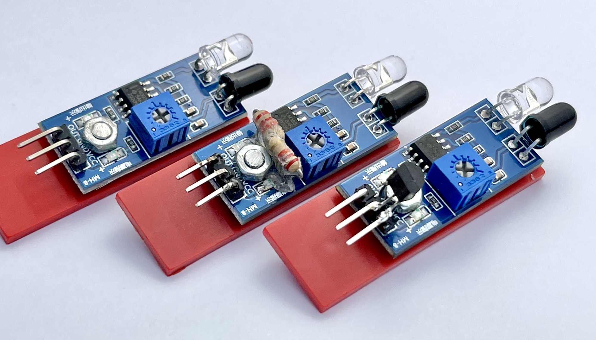
An additional advantage is that these modules can operate electronically without major problems at a higher supply voltage, such as the 9 volts of the Silberling. According to the datasheet, the LM393 voltage comparator used on the module can even handle up to 36 volts without any problems. The only problem is that the two smd leds on the PCB are set to 5 volts and light up very brightly at a voltage of 9 volts. And this visual detection feedback is actually very useful, so it would be a shame if they burn out because of this.
To make these sensors suitable for use with the Silberlingen (or the TXT controller) I tried two different modifications, both of which worked fine:
After a short test in which I replaced the photo-resistors from the previous model with the Silberlingen with the modified IR-obstacle sensors, the Zauberling came on the scene.
This allowed a number of points to be improved:
The Zauberling solved some practical problems as if by magic. Its flexible inputs make it possible to experiment with practical sensors outside the well-known fischertechnik range. The gradual changes of direction of rotation are much appreciated by fischertechnik motors and could not be achieved so easily with discrete electronics.
It's a nice first trick from the Zauberling. I'm curious what else he will conjure up from the top hat in the future. It will not be the cooperation with the Silberlingen, he has now been lovingly accepted into this traditional fischertechnik family and Mr. Lemniscate insisted that he be allowed to sit on the so wonderfully gradual 'floating' chair.