In the previous project, a contactless touch switch was proposed, the output of which can be used for digital applications without disturbing switching noise. These sensors require a supply voltage of 5 volts. To make them more suitable for use with the classic fischertechnik electronics modules that I like to use in experiments, I investigated, among other things, the signal output level of these sensors. Because I also came across a nice alternative to the touch switch discussed last time, I developed a small printed circuit board and a few different 3D-printable housings to be able to use the sensors worry-free at 9 volts with the so called 'Silberlingen' and other electronics modules from the fischertechnik system.
The sensor boards introduced last time are built with a TTP223 'Human Body Detector' chip. The TTP223-ASB chip is a 16-pin SMD component, but the sensor boards available online usually use a variant of this chip (TTP223E-HA6) with only 6 pins and slightly fewer configuration options. By default, the sensor behaves as a momentary push button, but by closing the solder jumper 'B' an on/off switching function (T-flip-flop) is obtained.
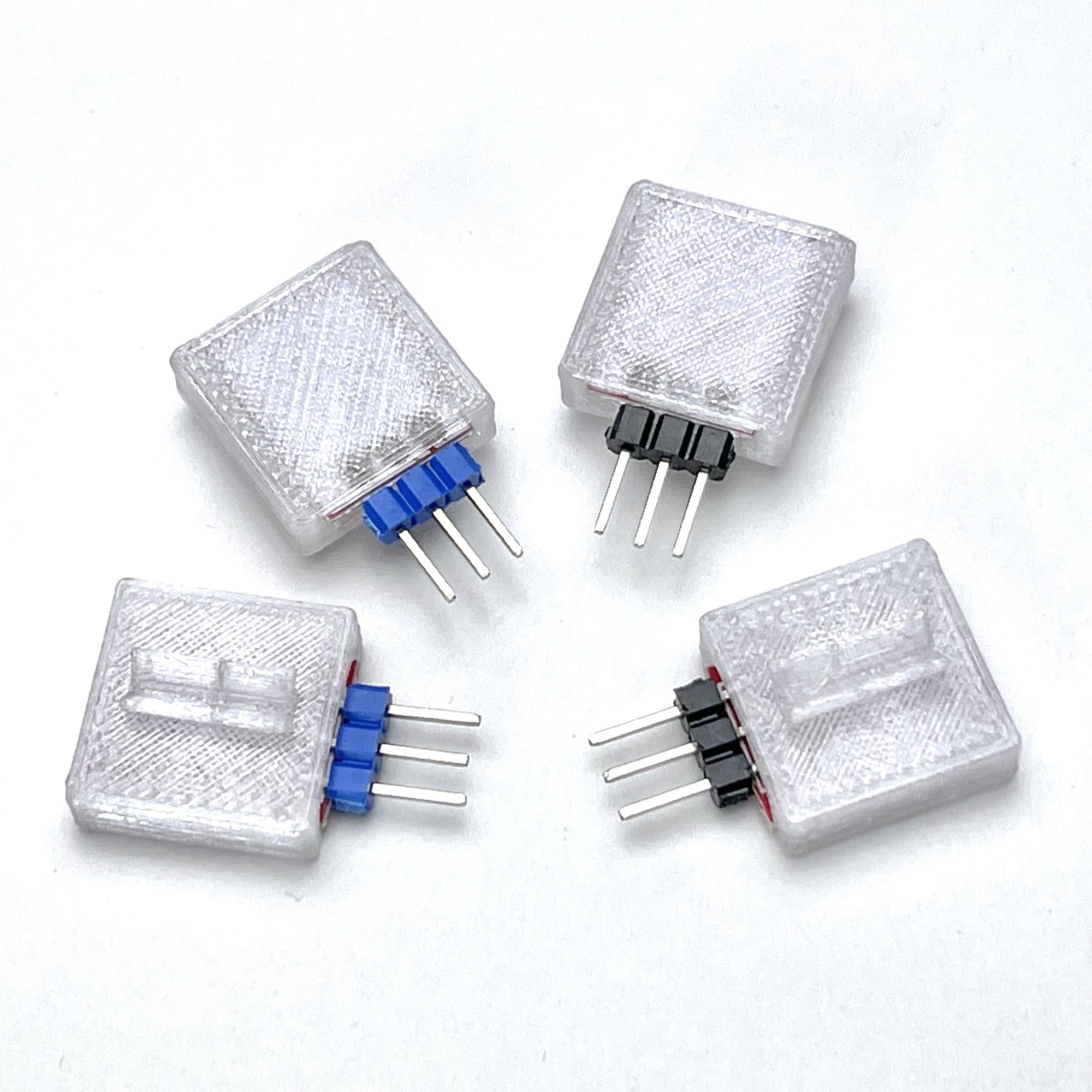
The image shows two DIY variants of the small sensor stone. For flawless touch detection, the transparent surface has been kept as thin as possible. The small sensor board is normally red in color, but was sprayed white on the top before installation, creating a transparent stone with a more neutral appearance.
As already established, many of these sensor boards operate on this 5 volt supply voltage, which is common for microcontrollers. The HW-763 sensor boards mentioned cannot operate at a higher voltage without modifications or self-built peripheral electronics. However, the operating voltage of the fischertechnik electronics modules and controllers that I like to use is traditionally 9 volts. For the classic electronics modules supplied with voltage by the GB Gleichrichter (30811) module, the operating voltage was even higher (approximately 11 volts). Before I investigated whether and with what modifications the sensors could possibly function on a 9-volt supply voltage, the facilities to provide a 5-volt supply voltage came in very handy again.
My own DIY experiments on this point have so far ranged from a very simple plug-in module on the rectifier module, to a model with multiple output voltages, voltage and current measurement and an adjustable automatic fuse.
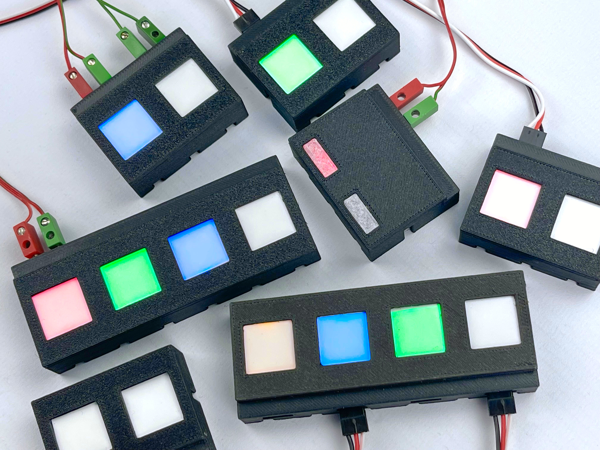
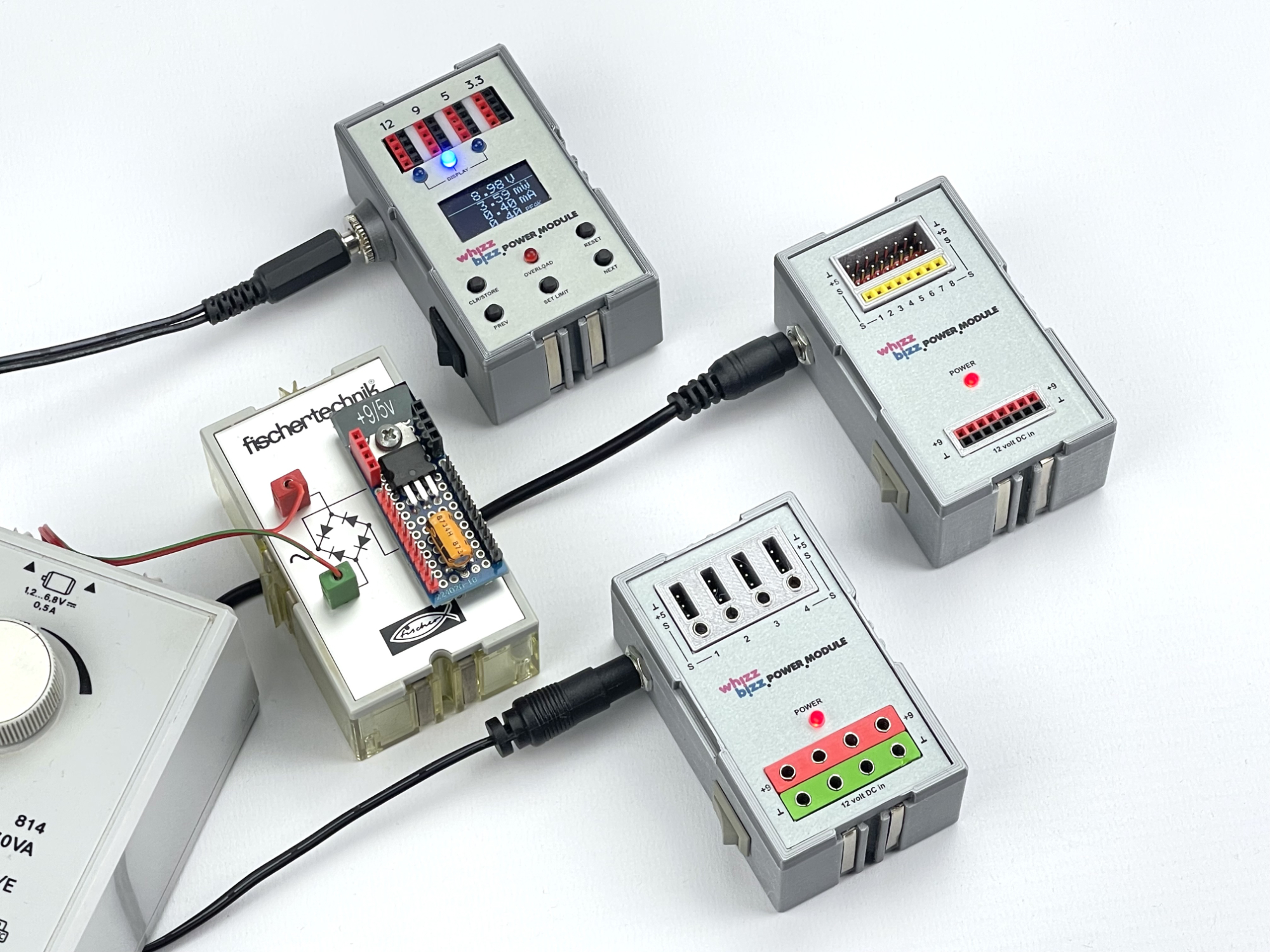
I recently added two models for future experiments with DIY 'Silberlingen' where the sensors can easily be powered with the common three-pin servo cables with the flat black (so-called Dupont) plugs. These power modules make it possible to experiment more easily with these 5 volt sensors. The photo also shows a model with 2.5 mm sockets for the fischertechnik plugs and a model with connection options for eight sensors equipped with connection rails for the single-pole colored experiment wires.
The small sensor circuit boards have a usable output signal whose voltage level can easily be read by a microcontroller. It is even irrelevant whether the sensor output produces a high voltage level on the output when detected (switching behavior with positive logic), or at rest (switching behavior with negative logic). Voltage thresholds and switching behavior can be easily adjusted in the controller software. However, if the output signal is to serve as an input signal for an electronics module composed of discrete electronics, direct compatibility is not always self-evident. For this reason, in the previous part of this article I was pleasantly surprised that the discussed HW-763 sensor modules with TTP223 chip, even if powered with 5 volts, could be used directly on the various classic fischertechnik electronics modules (affectionately often called 'Silberlingen').
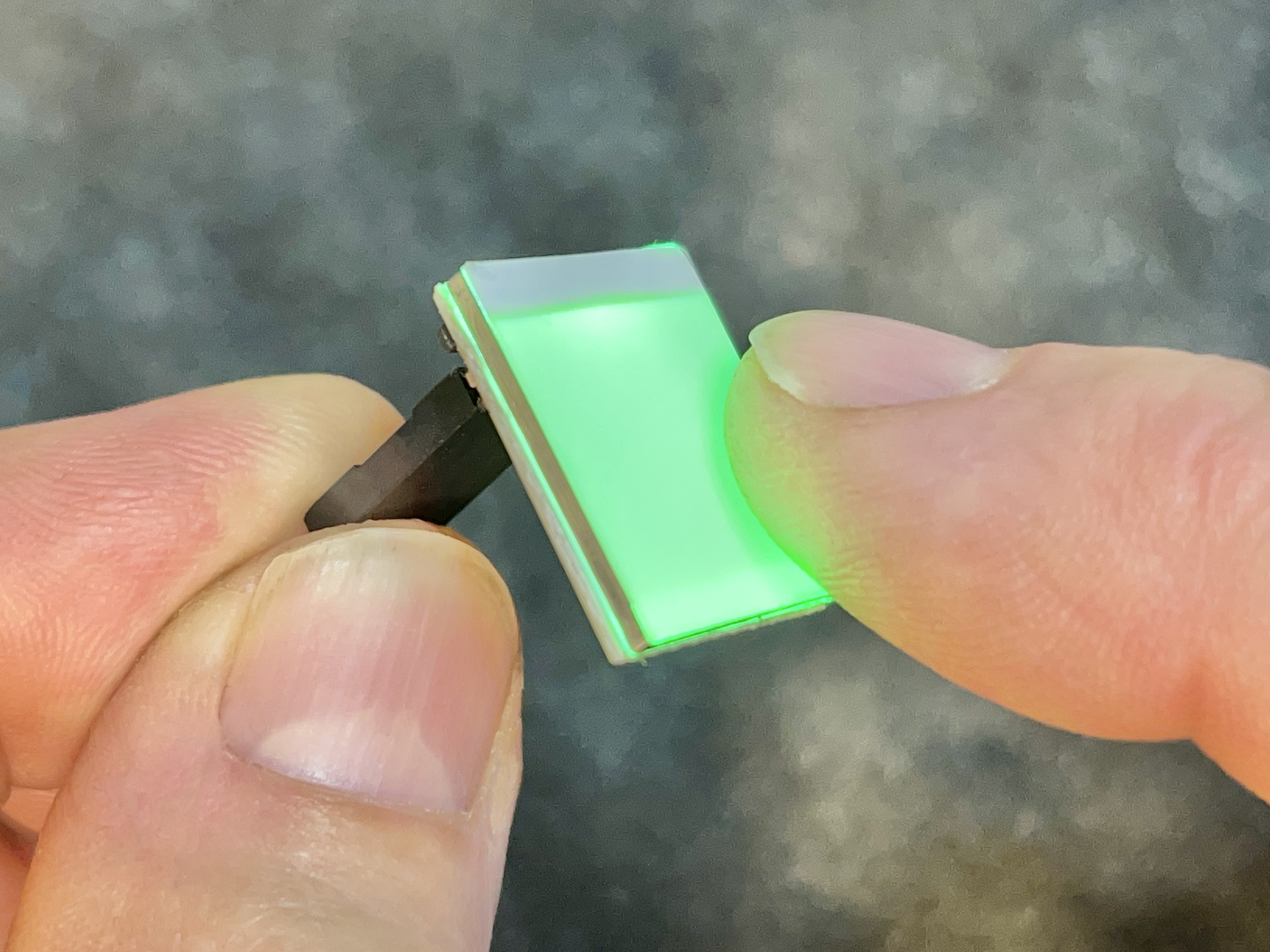
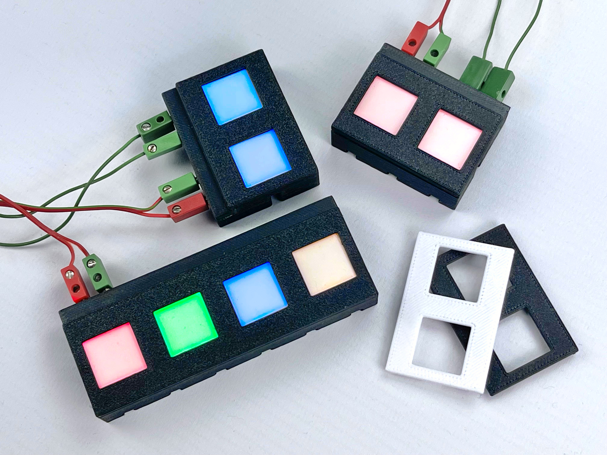
Not long afterwards I came across a variant of the sensor board in which the LED light illuminates the entire touch surface (see photo). This 'HTTM-Series' touch switch turned out to be available in various LED colors (red, green, blue, yellow and a kind of 'rainbow' variant). While in the previously discussed HW-763 sensor board, an LED on the bottom of the PCB must provide the desired visual feedback, with this attractive HTTM variant the switching could be made more easily visible when installed in a casing. For example, the sensor surface of this new sensor could remain directly visible and accessible through an opening in the lid. An additional advantage of this seems to be that it is clear to a user where to place their finger to activate the sensor.
This HTTM touch switch is slightly more expensive due to the white frosted glass LED diffuser and almost twice as large (20 x 16 mm) as the other 'Touch Switch Sensor'. A small difference is that the switching behavior is already pre-configured as a 'toggle switch' by a soldered jumper (0 Ω SMD resistor). There is no configuration option to influence the switch-on behavior by means of a solder jumper. Unfortunately, after these not insurmountable small differences, there also turned out to be a much larger difference. In contrast to the smaller sensor (which has a so-called 'open-collector' output), this sensor has an output with a very low impedance. As a result, the signal output is not electronically compatible with the conventional transistor-diode logic of the 'Silberlingen'. Because the 'Silberlingen' work with negative logic, an 'active' signal corresponds to pulling the relevant input to zero potential. The output of these LED surface touch switches is not capable of this due to the way in which the LED is connected to the output (to ground).
Because a voltage regulator is built-in, the voltage level of the output is only 3.3 volts. Again, detection of such an output signal from this sensor on an analog input of the TXT controller, or another microcontroller, will cause few problems. But when this signal level in a circuit with 'Silberlingen' has to be detected with the Elektronik-Grundbaustein G, we encounter another problem due to the low voltage level.
Detecting whether a signal level crosses a certain voltage threshold can be left to the Grundbaustein. A nice bonus is that at the output both the normal and the complementary (inverted) sensor signal are available on the outputs A1 and A2 of this module. The only connection that needs to be made is to connect the sensor output to E1. The fischertechnik Grundbaustein is basically a differential amplifier. As standard, (slightly less than) half the supply voltage is applied to input E2 by a voltage divider. This voltage forms the detection threshold of the signal level at E1. However, with a supply voltage of, for example, 9 volts, signals on E1 that move completely below the detection threshold of 4.5 volts will not be detectable.
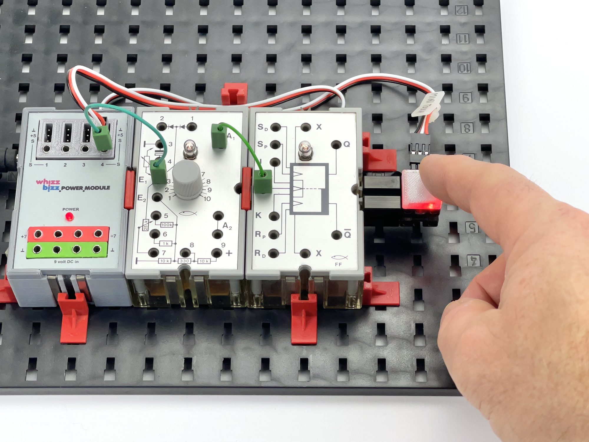
The small red HW-763 sensor boards have an active output signal of 4 volts and could therefore not simply be detected with the Grundbaustein. This indeed appears to be the case upon inspection. Because I also have variants of my power supply module that supply 7.5 volts instead of 9 volts, I could also quite easily check that the detection does take place with the 'Silberlingen' at this reduced operating voltage. However, this is still not a solution for the mentioned HTTM touch switches with an output voltage of only 3.3 volts. The supply voltage of the 'Silberlingen' should be reduced to at least 6.5 volts and such a low supply voltage could have repercussions for the switching stability and brightness of the indicator light in the Grundbaustein.
After some puzzling I came up with a (as far as I know, so far undocumented) way to lower the detection threshold of the Grundbaustein's differential amplifier without lowering the supply voltage. If the input voltage on E2 is reduced by adding a 10 kΩ resistor between bus 3 (or another 0 volt) and bus 6, the original supply voltage can simply remain 9 (to 10) volts. The voltage divider is adjusted by this parallel resistor in such a way that input voltages higher than just 1/3 of the supply voltage can be detected at E1. In this way, sensors with a low output level can also be used with the trusted 'Silberlingen'. See the principle diagram in which a resistor R is connected in parallel to the lower part of the voltage divider and reduces the detection threshold voltage on E2.
So there are certainly solutions to use 5 volt sensors with a relatively low output signal with the 'Silberlingen'. However, it would be more efficient if it could be operated directly on 9 to 12 volts and the output signal had the desired switching compatibility in all cases.
The desire arose to develop a universal printed circuit board on which both models of sensor boards could be housed. It would be preferable if the sensors could be supplied with 5 volts via a three-pole cable with a flat plug so that pre-fabricated cables can be used. A nice extra would be if it were also possible to connect the sensors with the traditional fischertechnik plugs. In the latter case, the sensors should operate at 9 volts and have a corresponding output signal. They can then be used with the 'Silberlingen' or TXT controller without the output signals having to be buffered or amplified in the manner described above with a differential amplifier in a Grundbaustein.
It is actually a pity that in practice the switching behavior of the sensor only has to be selected once (namely before final mounting on the printed circuit board) with the solder jumpers. It would be much nicer if this could be configured later as needed. For this reason, a jumper was included on the new printed circuit board for each sensor, which allows the switching behavior to be changed later after removing the cover.
The small red HW-763 sensor model also has a solder jumper that, when closed, reverses the signal behavior of the output. When the supply voltage is applied, the output voltage of the output signal is immediately approximately equal to the supply voltage and upon detection it drops to zero level. This seems ideal for use with the 'Silberlingen', who traditionally work with negative logic. But unfortunately this jumper setting does not affect the behavior of the indicator LED. In fact, it still follows the positive logic, which unfortunately makes this mode seem of little use in practice. Although I took into account an extra jumper for this in the circuit board design, I omitted this option. The HTTM sensor does not have this option anyway.
In the 9 volt version it was simpler to simply invert the logic levels of the output anyway. The switching behavior of the output is then according to 'negative logic', which means that it can be used with the 'Silberlingen' without inversion of the output signal.
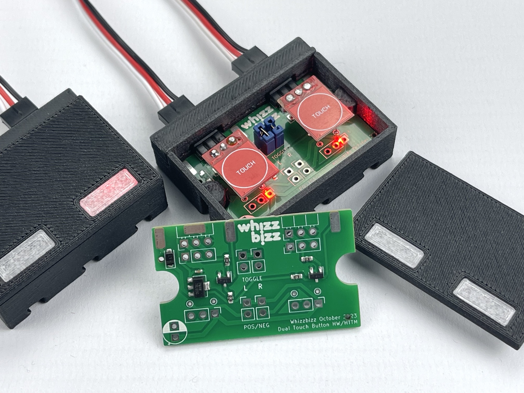
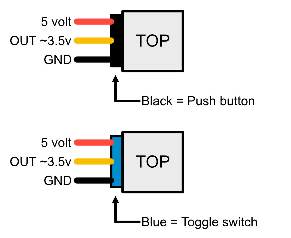
When mounting the sensor boards (two per PCB), I connected one side of the 'TOG' jumper to the PCB with a small wire. On the HW-763 sensor board this is marked as solder jumper 'B'. On the HTTM board with the larger LED light area, this is only the only solder jumper. The 0 Ω SMD resistor that activates the 'toggle' behavior by default must first be removed.
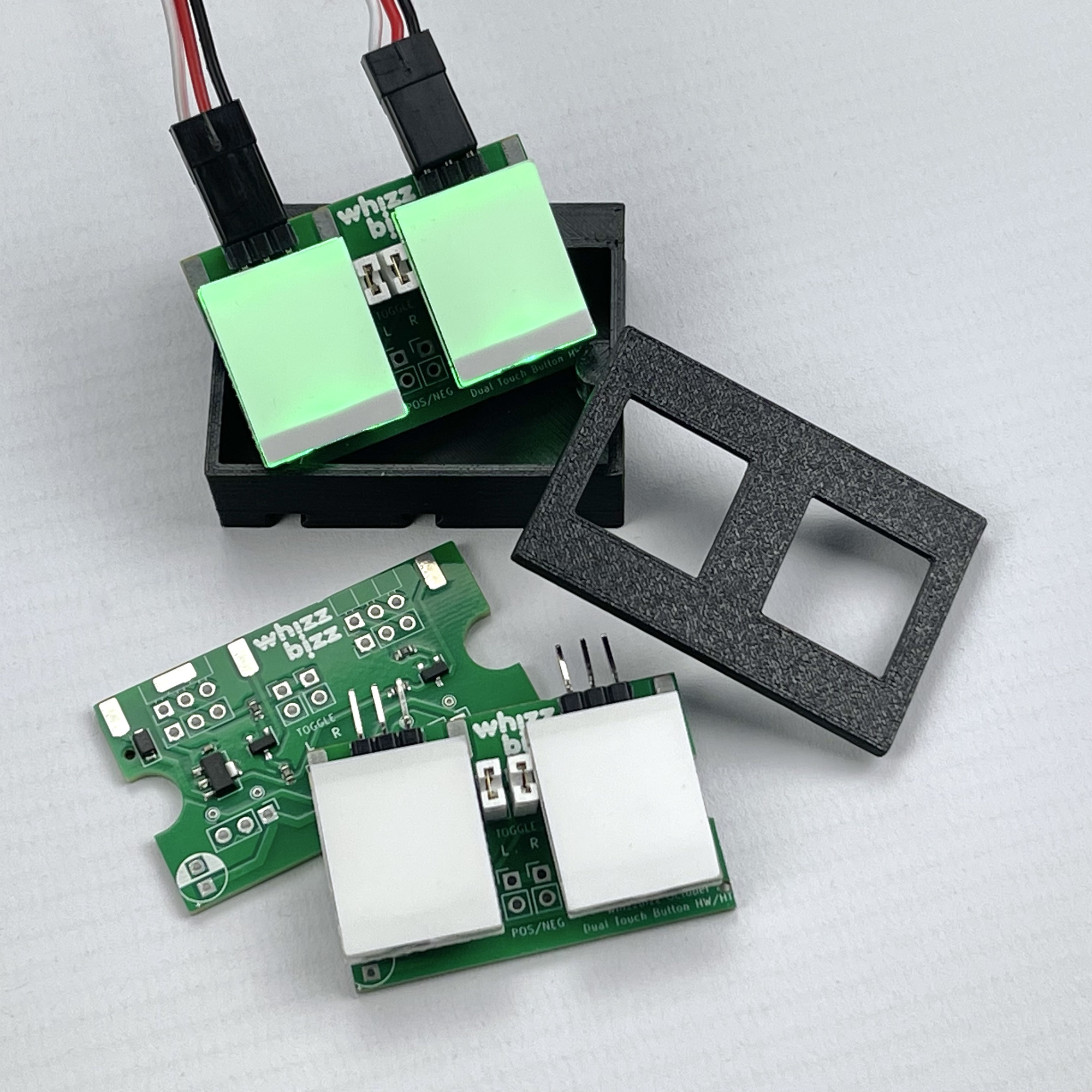
In the photo the circuit board with two double illuminated sensors ready for mounting.
The final mounted touch switches can be connected on the sensor side with standard servo cables. Note that the pin order of the small HW-763 sensor stones is different, however. Cables with three loose pin plugs on one side and 2.5 mm fischertechnik plugs on the other side are therefore very practical. The connection cable shown below was made by myself, but it is of course also possible to cut a ready-made cable in half and screw in fischertechnik plugs. This way you immediately get two usable connecting cables for little money.
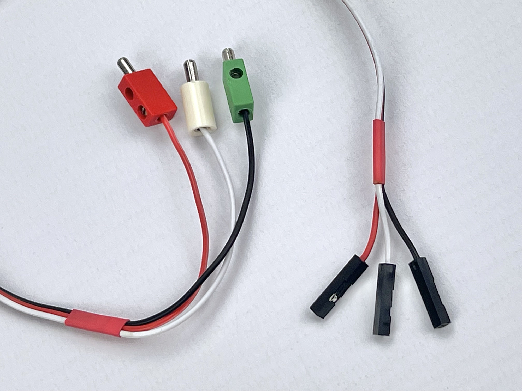
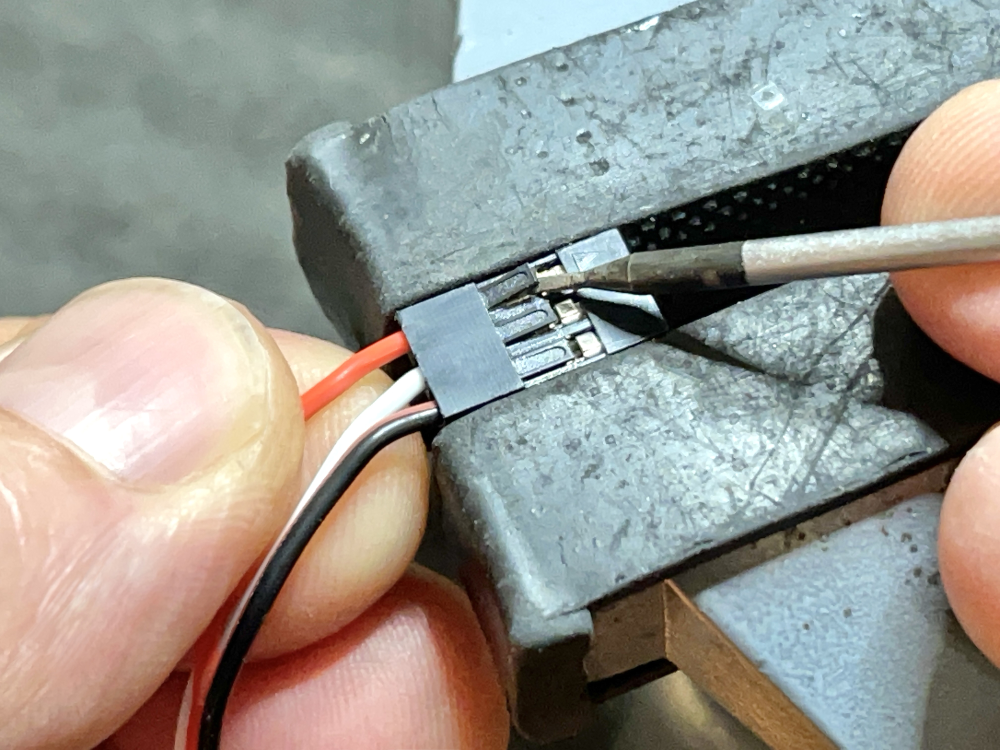
With three separate pins it is easy to choose the desired connection order for each sensor, but these cables are (as far as I know) not available ready-made. Fortunately, the pin order of the three pins in the standard 3-pin servo cables (where the positive pole is designed as the middle wire) is quite easy to change. Carefully clamp the plug briefly in a vice. Gently lift the small plastic locking tab of the pin to be removed with a small screwdriver and pull the connector pin out of the plug by the wire. If necessary, press the plastic lip flush with the plug housing again. Then reinsert the pins in the desired order to create a custom-cut connecting cord.
The next step was to design the different housings for the different plugging methods. Different desks were also required for the different sensors.
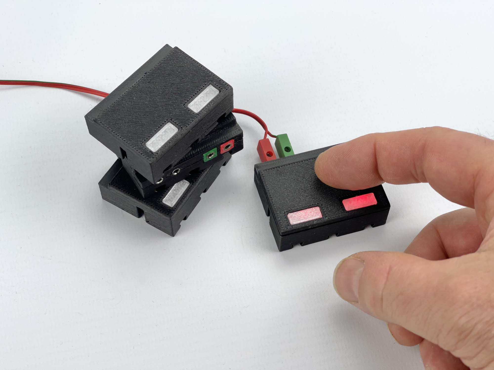
The photos show the variant in which two sensors are housed in a closed, 3D-printed housing. The (red) LED that lights up upon detection is located on the bottom of the small sensor circuit board. Thus, built into a semi-transparent enveloping building block or (splashproof) closed housing with diffuser printed from transparent material, this LED light is sufficiently visible. However, during the practical test (at the fischertechnik Südconvention) it turned out that one sometimes intuitively places the finger on the diffuser instead of slightly higher (where the detection surface is located under the lid). Fortunately, in most cases the sensor turned out to be sensitive enough to detect such a touch.
For the HTTM variant I designed and printed a box in which the sensor surface of each sensor remains visible through the lid. As with the closed variant, I also experimented with a double variant that directly houses four sensors. The idea is to use this in the future for digital experiments, where four bits can be 'programmed' per module. I made a version of both variants that works on 5 volts and can be connected with a three-pin cable, and one that uses the well-known 2.5 mm fischertechnik sockets and works on 9 volts.
Experiments were conducted with different versions of the TTP223 detector boards. The small HW-763 board can therefore even be housed in a 5 mm thick transparent building stone. The sensor is sensitive enough to be activated by the thin lid of a closed enclosure. For the 'HTTM-Series' version of the sensor board, where the entire touch surface can light up in color, the sensors must of course be accessible via holes in the lid of the housing. The light output and visibility of the yellow-illuminating sensor is the lowest, personally I think the green-illuminated sensor is the most clearly visible.
In order to mount the sensor boards as close as possible under the lid, I printed a small mounting aid on the 3D printer that determined the exact mounting height during soldering. A completely assembled sensor circuit board, which also has the three-pin connector directly on it, slides easily into the housing and is clamped by the lid. Making the versions with fischertechnik sockets turned out to be very labor intensive. Due to the limited installation space behind the sensors in the housing, the buses could only be connected via a loose backside with internal wires that could be glued after installation. I used the discussed PTN2-10 sockets as connection sockets. Because manufacturing an adapter cable, as shown in the photo above, is relatively simple, after these installation difficulties, the choice of the small flat three-pin plug on the sensor side is absolutely preferable in the future.
Both the 9 volt and 5 volt versions of the sensor can be used with microcontrollers or the TXT controller from fischertechnik. The 5 volt version is connected with a standard three-pole servo cable. The output of the HW-763 variant can be used directly as an input signal of 'Silberlingen'. However, the 5 volt HTTM variant can only be operated in the manner described above via a Grundbaustein. Perhaps it would be worthwhile to develop a modified version of the printed circuit board in which the supply voltage always runs via the voltage regulator and which ensures better electronic compatibility with the inputs of the 'Silberlingen'. The choice between 5 or 9 volts supply voltage then becomes completely trivial.
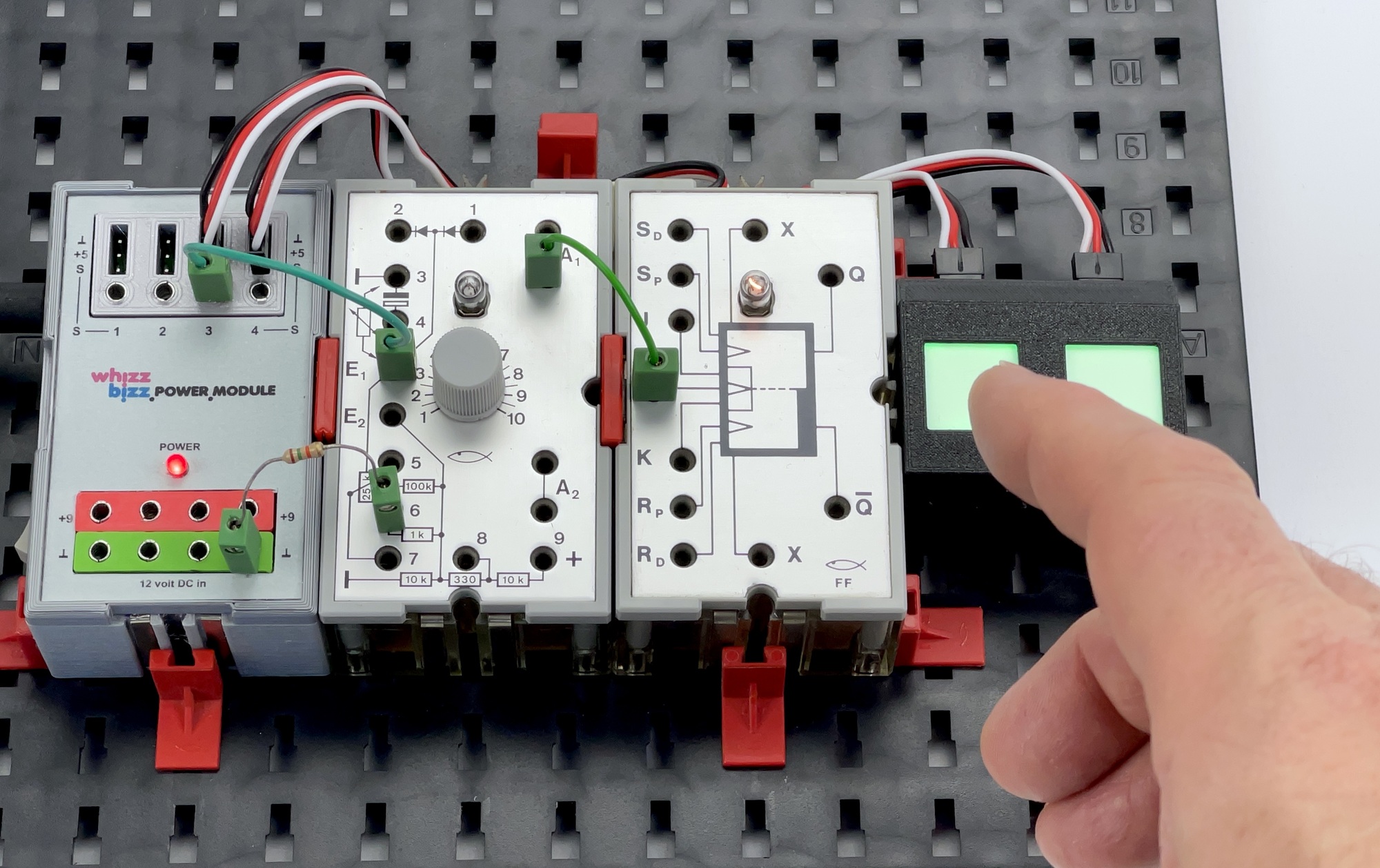
The 9 volt versions of both sensor cases provide the internal supply voltage for the sensors (5 volts) themselves, and are also equipped with an output that can consume enough current to be used with it directly on the inputs of the 'Silberlingen'. The sensor output can therefore be used excellently to trigger the Flip-Flop (30815) or Mono-Flop (30816), for example, or as an input for the OR/NOR (36481) or AND/NAND (36482) modules. It can also directly control the relay module with built-in amplifier (36392). This makes a series of these touch sensors eminently useful, for example, to serve as bit inputs for a digital circuit constructed from 'Silberlingen'.
It is most useful if the sensors can be modified in such a way that they work directly on 9 volts and the signal output is electronically compatible with the 'Silberlingen' as much as possible. This was also the starting point for making a number of other sensors applicable in the continuation of my search for contactless switches.