
A recurring issue for electronics and computing tinkerers is physical electronic compatibility with existing building systems. The choices for existing components, controllers, sensors, etc. with their own specific connectors often determine which plug and wiring system the self-built microcontroller or electronics module should ideally be equipped with. Anyone who, like me, works a lot with fischertechnik construction materials knows that it is sometimes useful if the classic flat 2.5 mm plugs of this system can be connected directly to your own electronics. In this article I discuss some ideas for the required sockets into which these plugs can be plugged. Although the emphasis is on the plugs used by fischertechnik, these solutions also seem useful for other brands and diameters of plugs.
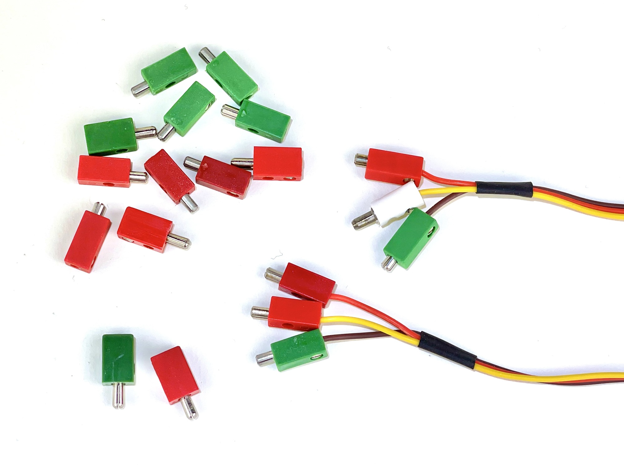
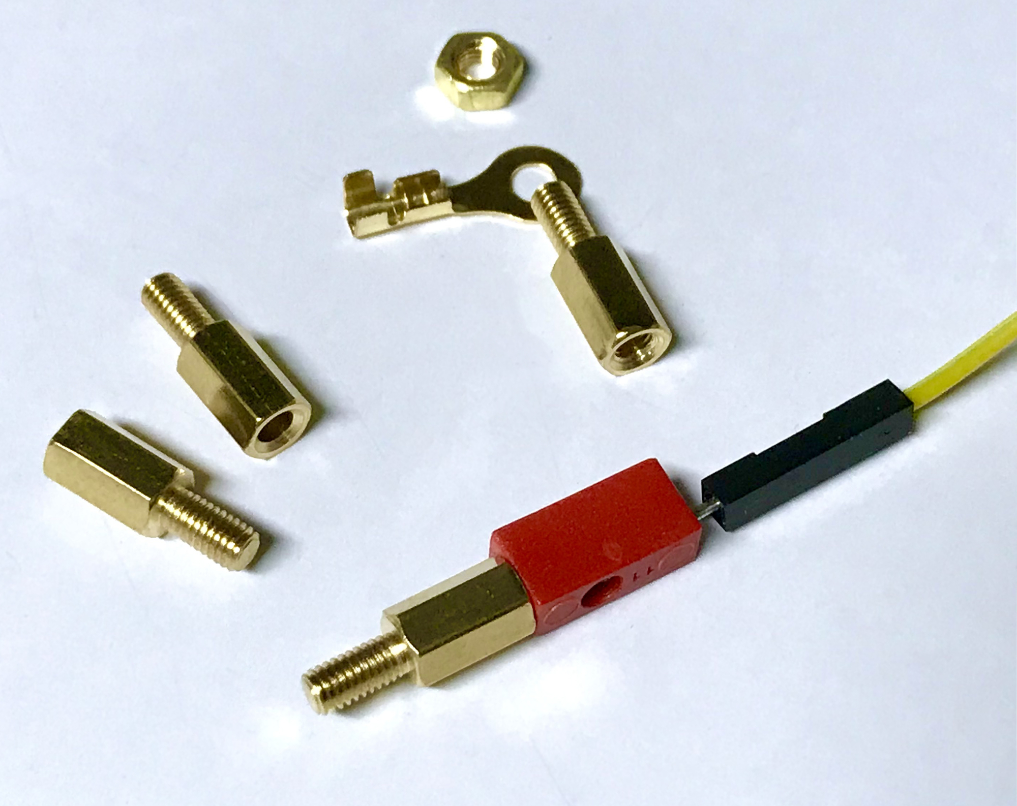
In principle, different connection systems can of course be used interchangeably in one project. For a DIY module with Dupont pin strips, the easily and cheaply available breadboard experiment wires can be used. If a traditional fischertechnik sensor, push button or motor needs to be connected, a fischertechnik plug can simply be screwed onto the 'male' core pin of such a wire as shown in the picture below.
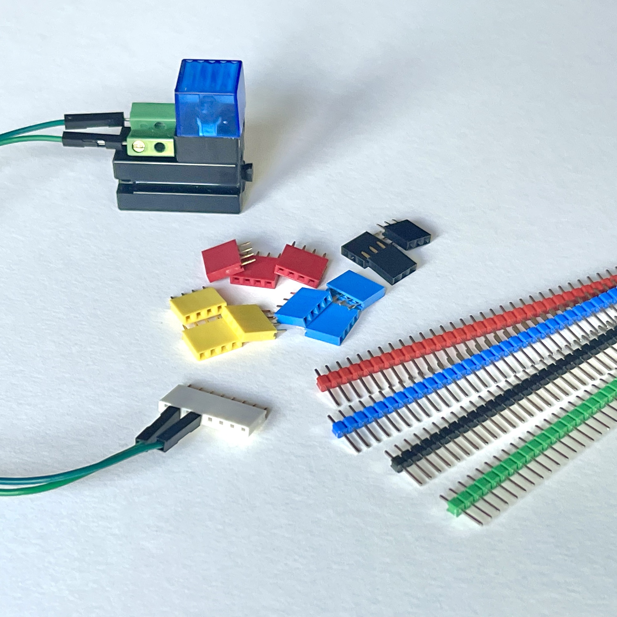
I hope not to antagonize the fischertechnik purists by first listing some (in my view) strong advantages of using the so-called Dupont 2.54 mm pin lists:
The above points are not necessarily listed in order of importance, but the argument of point 1 carries quite a lot of weight for me personally. Especially in self-build projects that are housed in fischertechnik cassettes or 3D printed housings with the dimensions of the traditional fischertechnik 'Silberlingen'.
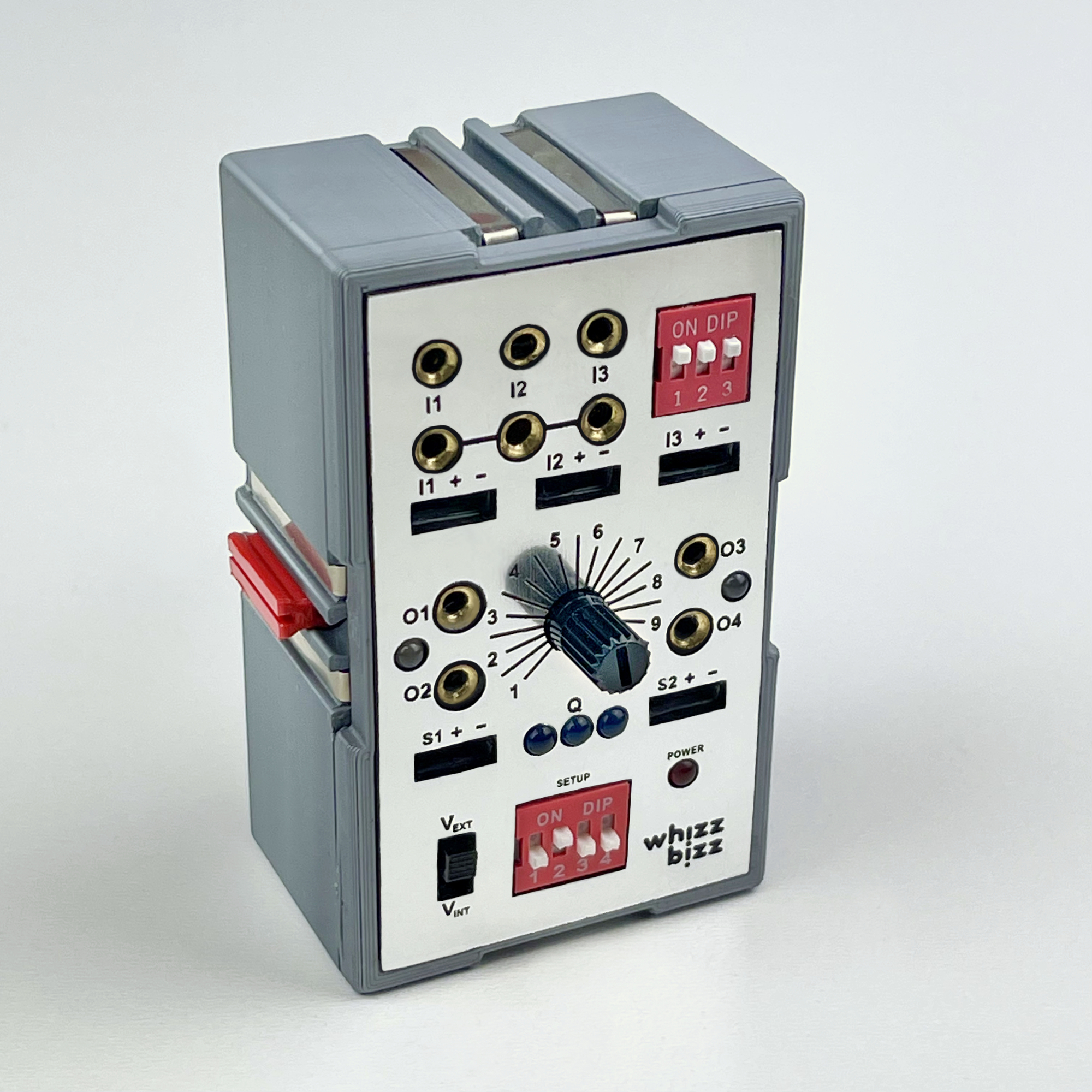
To illustrate: the first 'Zauberling' (photo here) was still equipped with sockets for connecting fischertechnik plugs, to accommodate all connection options on the front of the later model offered by the increased connection requirements and by other elements on the front. space, only Dupont 'Pin Headers' solution.
Even on the front of the “hl1 EF Experimentier Feld” building block (37140), on which 43 2.6 mm sockets are brought together, each socket still requires 7.5 by 7.5 mm surface area. One such surface can house 9 Dupont pins, which can also be color coded if desired.
In my opinion, the last point in the list above is not the most unimportant. The Dupont pin headers are available at a very affordable price and cost a fraction of the price that has to be paid for the so-called 'Bundhülsen' (solderable pipes with an inner diameter of 2.6 mm that are available in different lengths). At the time of writing, I could only find a few ordering addresses for this simple passive component. However, anyone who needs a large number of these buses for a project will quickly spend more on 'Bundhülsen' with a unit price of between € 0.30 and € 0.50 than on any other active electronic component on the printed circuit board, including microcontrollers! This is of course very surprising and explains the creativity of many self-builders who want to equip their self-build module with alternative connection options to the traditional fischertechnik plugs.
An option that we should certainly consider for the sake of completeness is that where the fischertechnik plugs are connected completely without sockets. Creative members of the fischertechnik community have already experimented with solutions to allow the 2.5 mm fischertechnik connection plugs to be plugged into self-built controllers or modules with switching logic without conductive sockets.
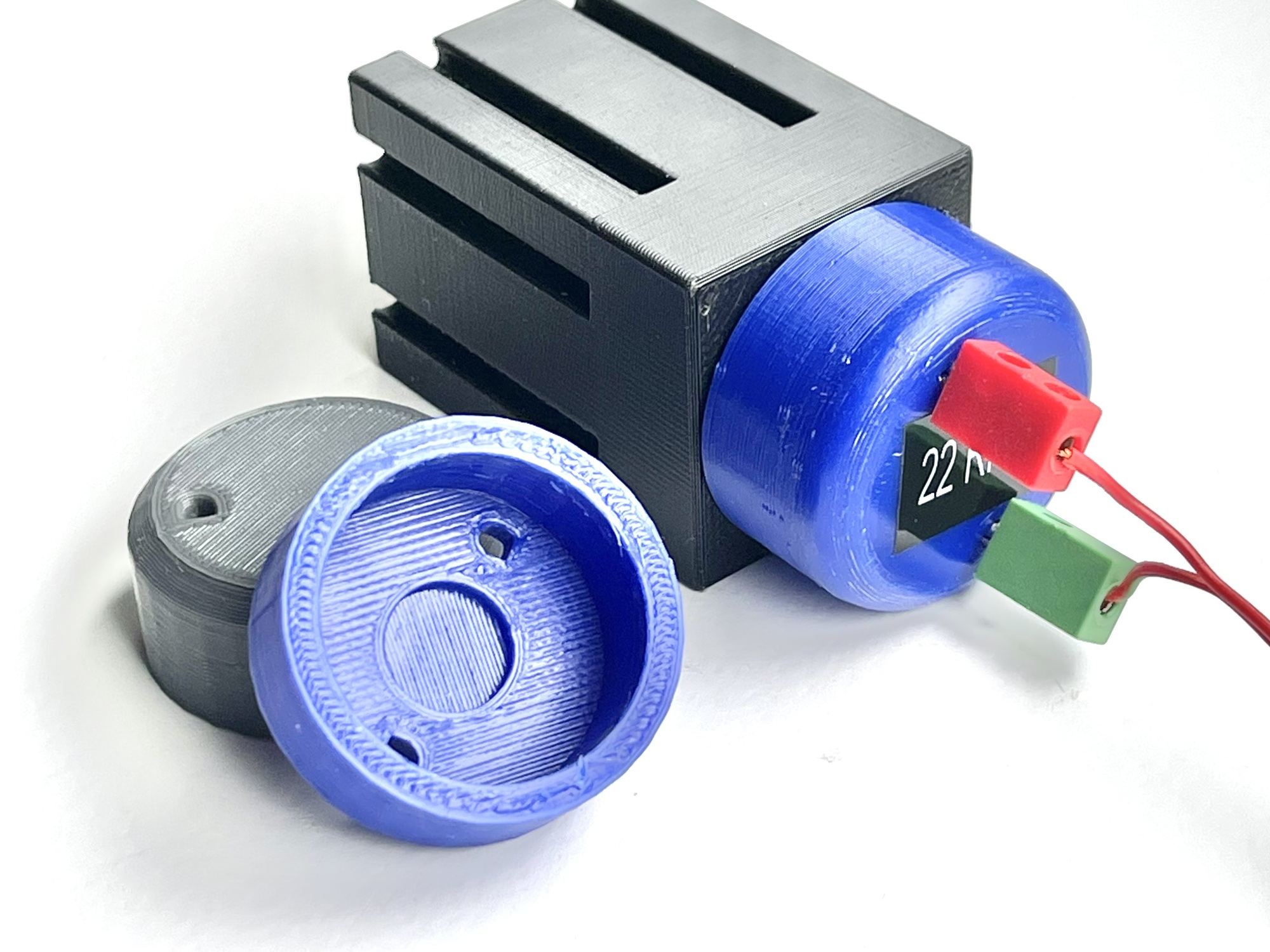
Somewhat inspired by this, I designed and printed connection caps for the ZGB25RP and JGA25-370 motors. Both the motor housings and the covers are 3D printed. When plugged in, the Fischertechik plugs make direct contact with the soldering lips on the back of the motor.
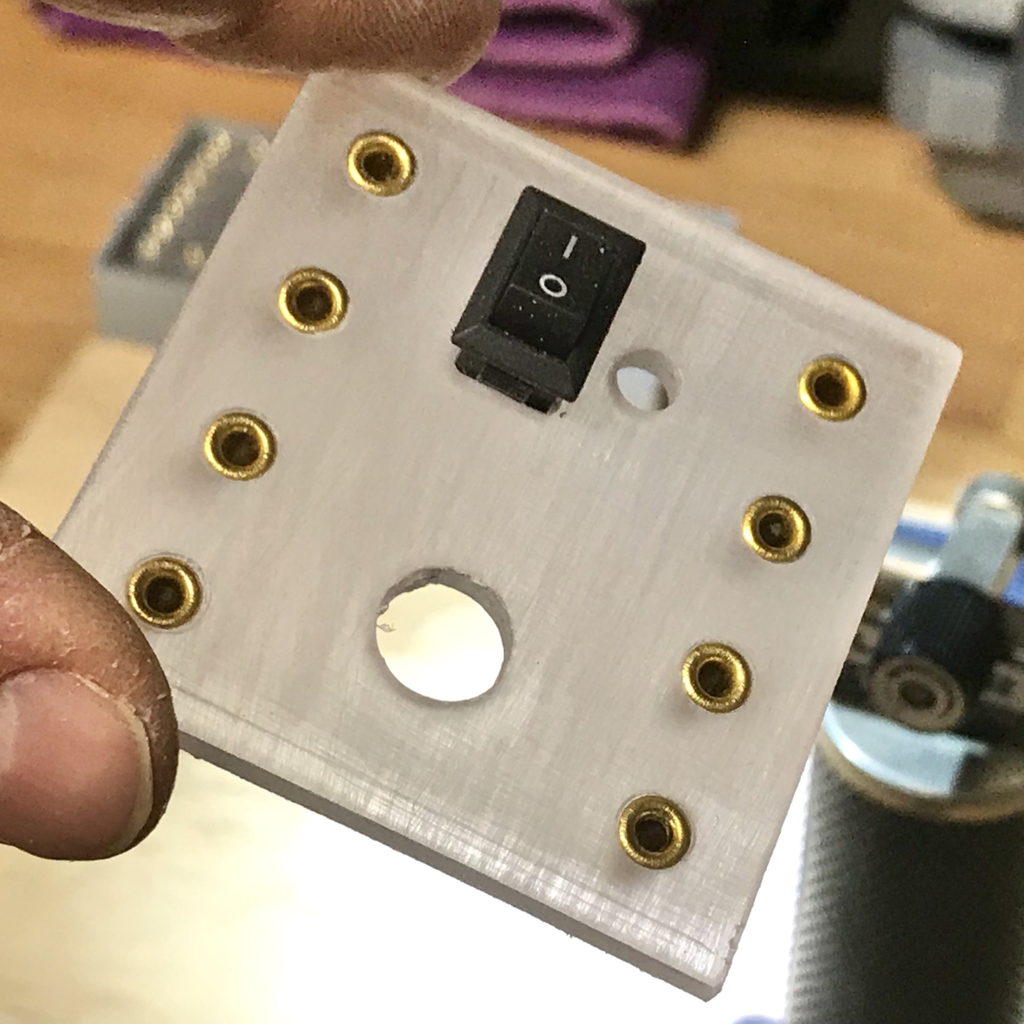
In the search for usable bushes with an inner diameter of approximately 2.6 mm, I came across the hexagonal copper M3 spacers. If the slats of the fischertechnik plug are bent slightly apart with a knife, these so-called 'M3 Hex Brass Spacers' can be used without any operations.
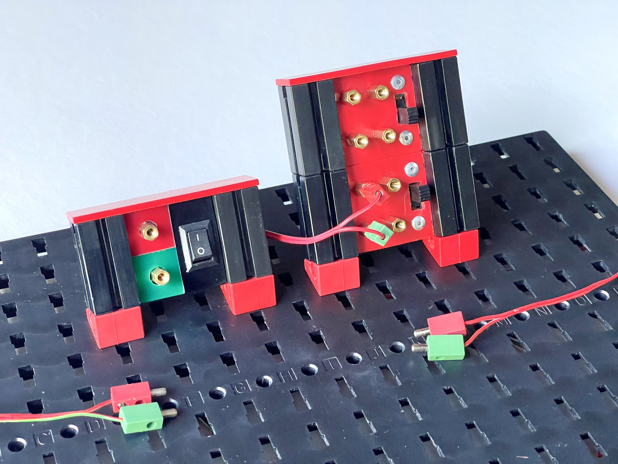
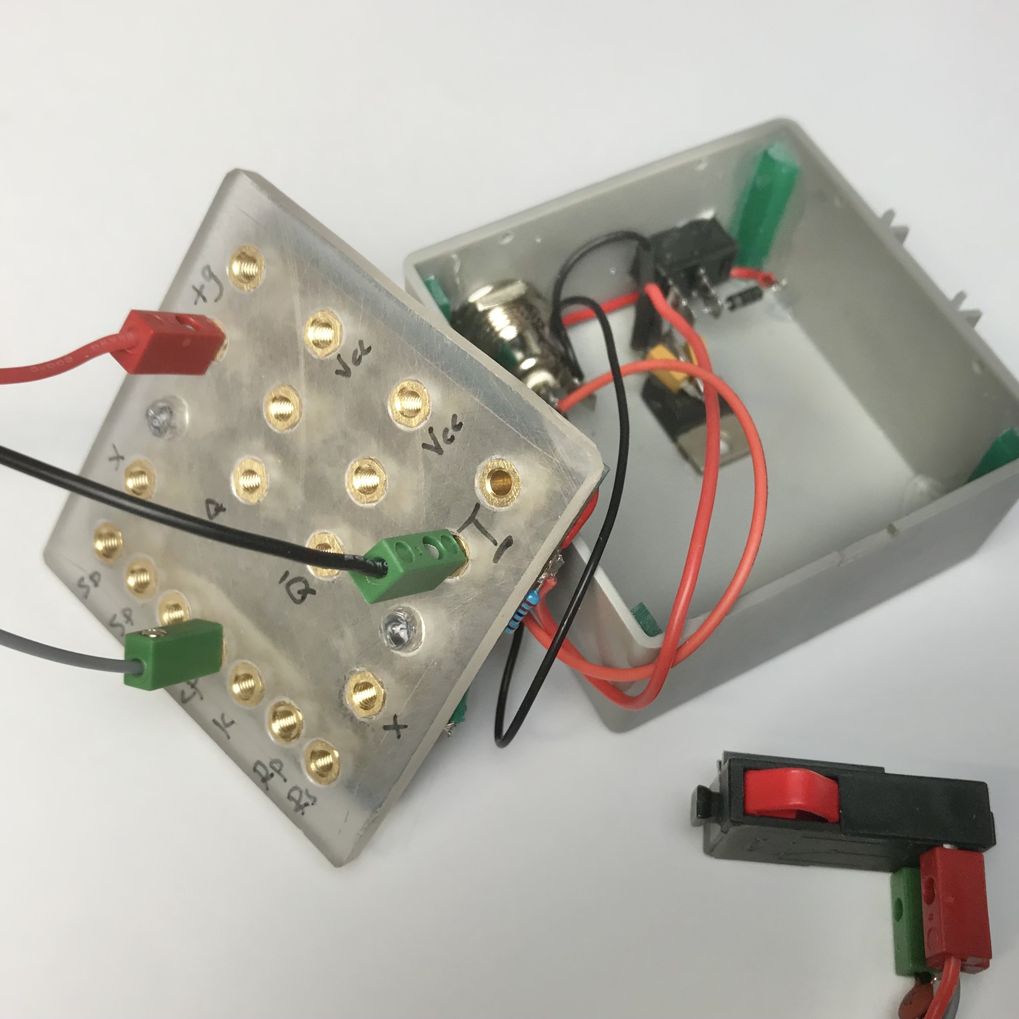
An advantage is that these spacers can easily be screwed into thin plastic, a plexiglass front or flat building block. For example, a handy on/off switch can easily be made with a Flachstein 30 with V-Riegel (31013). The connecting wires can be soldered to a solder lug inside or on the back. They can also be melted or glued quite easily into a pre-drilled front, after which the printed circuit board can be soldered directly to the back of the front. I used this method for a DIY flip-flop in a fischertechnik cassette (35359).
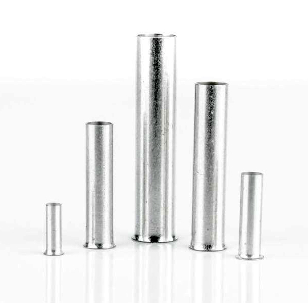
A solution that several people have experimented with is the use of so-called ferrules. The type of sleeves without the color insulation is very similar to the original 'Bundhülsen', is easy to solder and apparently only lacks the ridge around which the sleeve rests on the printed circuit board. These sleeves can be soldered on a large soldering island on the printed circuit board, just like the 'Bundhülsen'.
A major advantage is affordability; the sleeves rarely cost more than a few cents each. A major disadvantage, however, is that the inner diameters of these sleeves are tailored to the most common cross-sectional areas of multi-core mounting wire. The inner diameter of these sleeves for 2.5 mm2 wire is ~2.4 to 2.5 mm, just too small for the 2.5 mm fischertechnik plugs.
The ferrules for 4 mm2 wire, with their inner diameter of ~3.2 mm, are unfortunately (much) too wide for the fischertechnik plugs. But these can perhaps be carefully pinched into an oval shape so that the fischertechnik plugs remain firmly in place. However, a connection with a better fit is obtained by carefully hammering 2.5 mm2 sleeves a little 'wider' with a Torx T-10 screw bit. If you have a drill stand with a machine clamp, you can drill out the sleeves with a 2.5 mm metal drill. All these operations are of course preferably carried out before soldering to prevent too much force on the soldering islands of the printed circuit board.
Very similar to the ferrules mentioned above are the copper hollow tubes which are available in different lengths for a few cents each.
However, the starting point for sizing these sleeves is again the common wire cross-sections, so that again only the 2.5 mm2 variant is eligible. As with the ferrule of those dimensions, it will have to be 'prepared' by drilling out one of the sides with a 2.5 mm drill. The fit of the fischertechnik plugs is also very good.
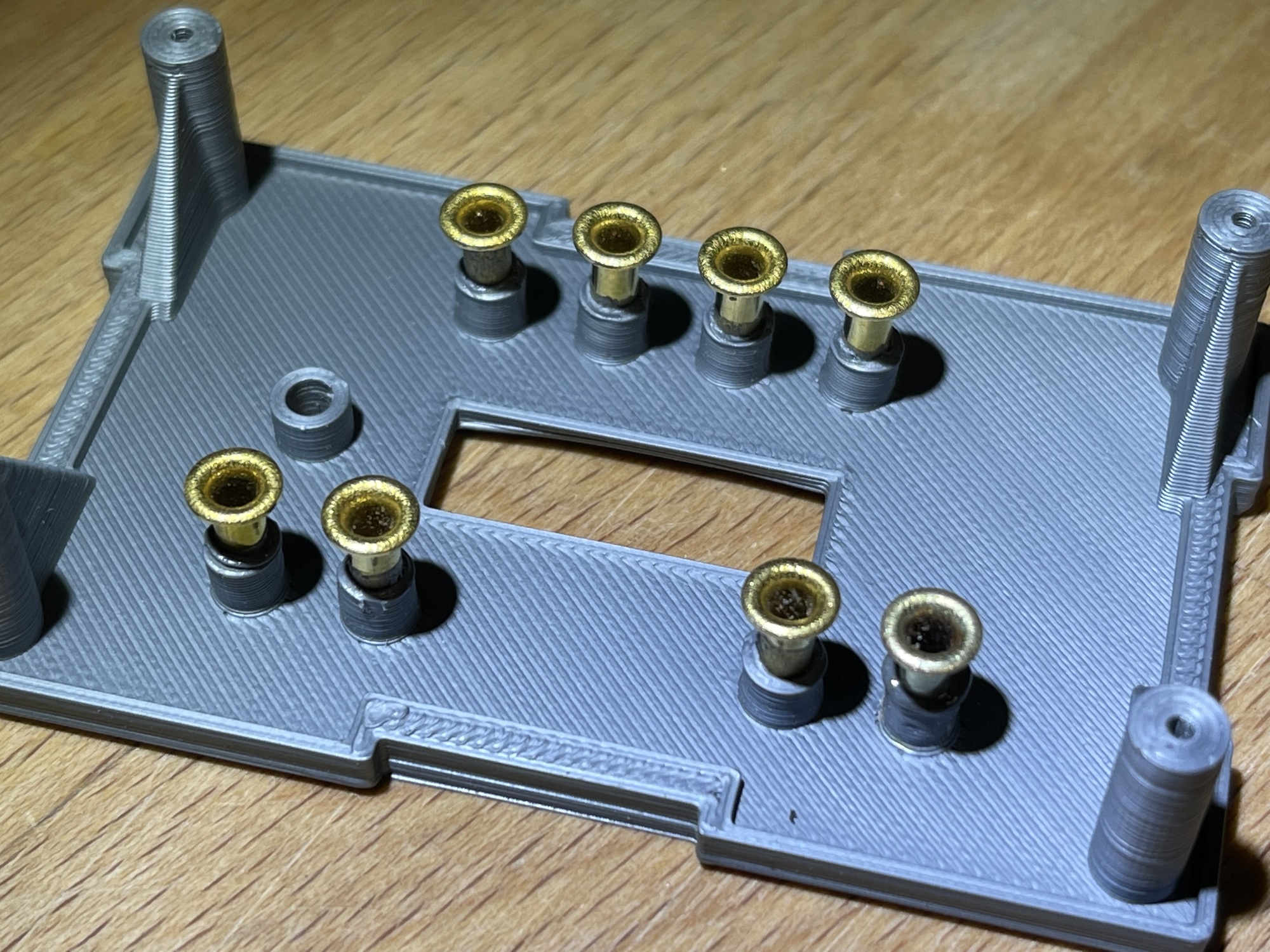
The pre-processed hollow rivets can easily be melted into holes that are drilled slightly too small or 3D printed tubes in the front, causing them to become very stuck. The photos show both the installation method in which the trumpet-like gabled side was drilled out and the installation in which the emerging pipe end of the hollow rivets was drilled larger (see images). With both methods, the bus can ultimately disappear completely behind the front plate.
The pipe ends can be connected to the printed circuit board behind the front in various ways. Or by direct soldering to the printed circuit board hanging directly behind the front. The advantage of this is that it does not require additional mounting with screws, a disadvantage may be that relatively large solder islands will have to be saved.
Another way is to attach the buses to the PCB using wires. This is more work, but quickly saves a lot of surface on the PCB if connections, such as power supply voltages or ground connections, are designed multiple times as rails. After all, identical buses can be connected directly to each other with an uninsulated piece of mounting wire behind the front and then only require one soldering island.
The 'Bundhülsen' are usually tinned, but the copper hollow nites often have an oxide layer, which can make soldering difficult. A tap with the polishing disc or cutting disc of the multi-tool or hand drill/grinding machine works wonders in such a case. In my case, by grinding a small slot (be careful with heat development, which can cause the sleeve to melt loose, especially 3D filament softens quickly at higher temperatures), the wires could easily be soldered on. The same tip of course applies to the M3 spacer bushings or other copper bushings that you want to solder properly without soldering lips.
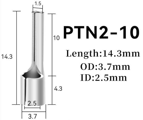
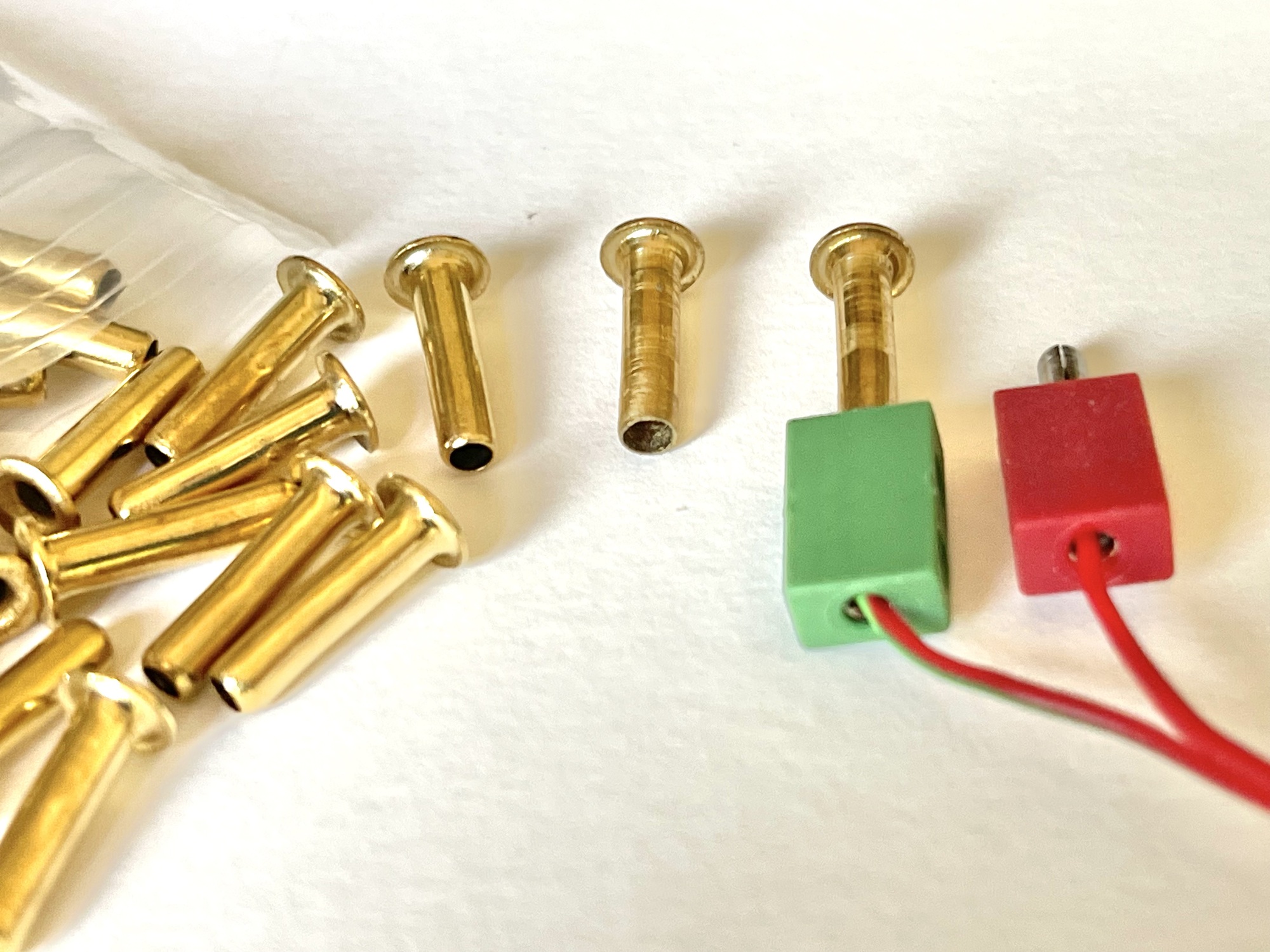
Some time ago, while looking for possible usable connection alternatives, I came across the PTN2-10 cable lug ('crimp terminal'). The online advertisement showed the specifications of figure 14. There seemed to be a few clear advantages to this model. First, the bus ends in a relatively thin solderable pin that only requires a 1.6 mm PCB bore. Although the specified internal diameter of 2.5 mm would be quite ideal for our application, it seemed to me that this can could be made wider quite easily due to the folded open construction if that were necessary.
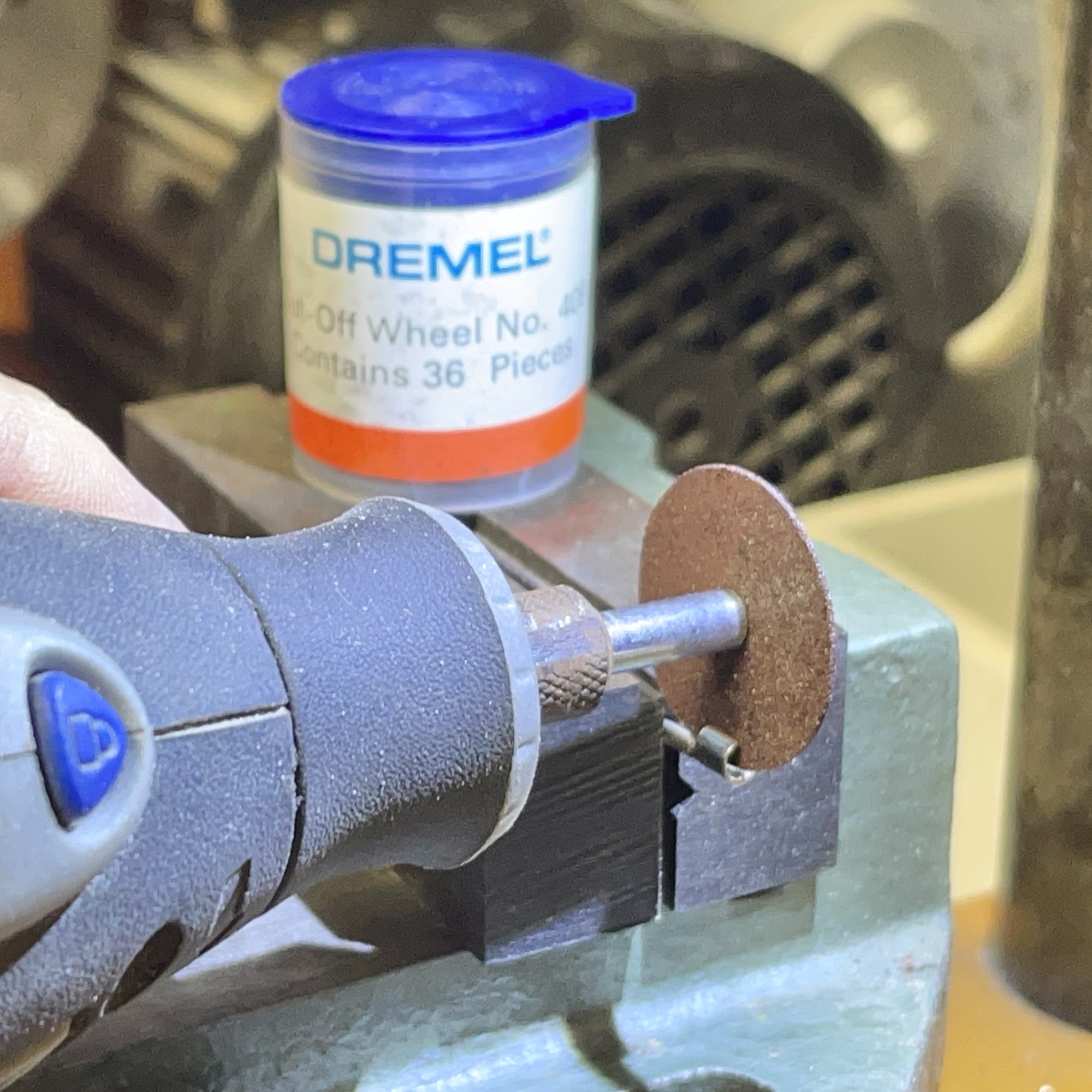
However, upon receipt it turned out that these were uncertified specifications from China. The actual inner diameter of these cable lugs turned out to be on the large side at approximately 2.7 mm. The fit is comparable to the M3 spacers, and therefore they initially only seemed suitable for plugs with 'widened' blades. The closing seam of the metal of the plug hole can easily be ground a little wider with a thin grinding wheel (Dremel 'Cut Off Wheel No.409' 0.6 mm thick). If the closing seam is then carefully pinched, the fit of the fischertechnik plugs is really good.
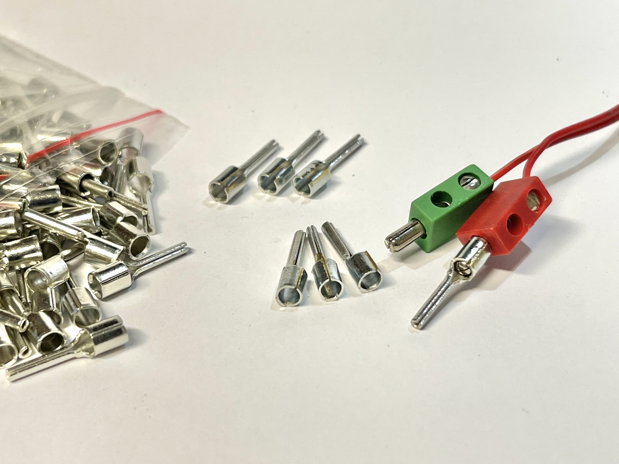
The first image below shows the various stages of pre-processing. On the left the original cable lugs, in the back center some specimens with a closed closing seam and below them the specimens of which this opening has been carefully closed. As can be seen on the far right, the fischertechnik plugs then fit perfectly.
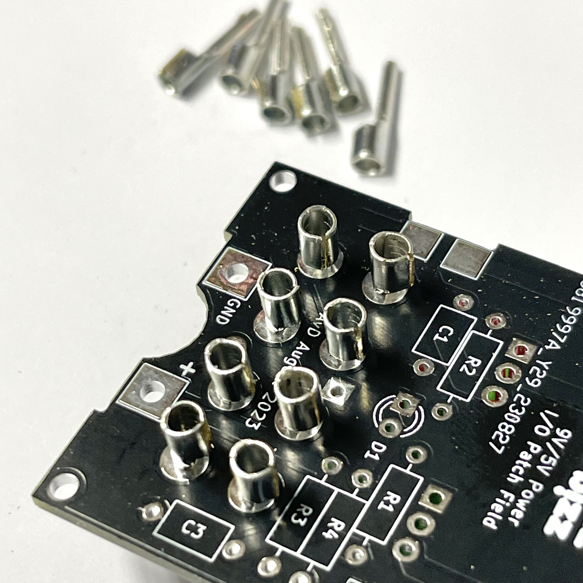
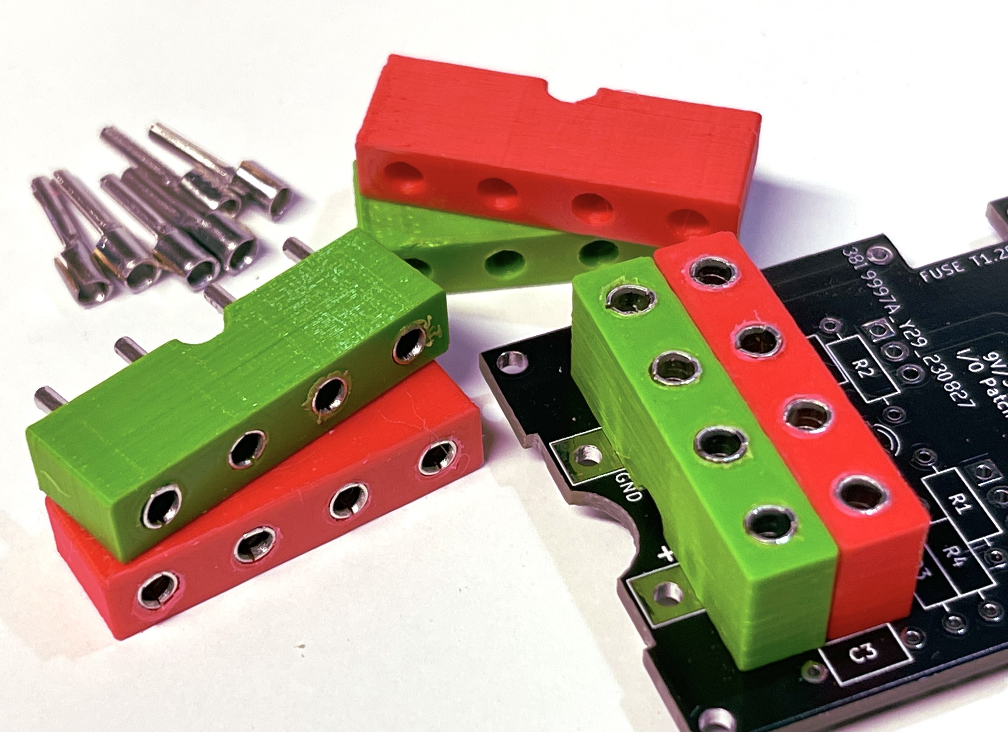
As shown in the photos above, the buses can be mounted directly on the printed circuit board. However, due to the short length of these buses, they cannot be placed too far behind the front of the module. However, due to the relatively long soldering pin, the sockets can of course be mounted a little higher if desired. This is easy to do with a 3D printed bus holder. An advantage here is that the colors can be used to clarify the connection function.
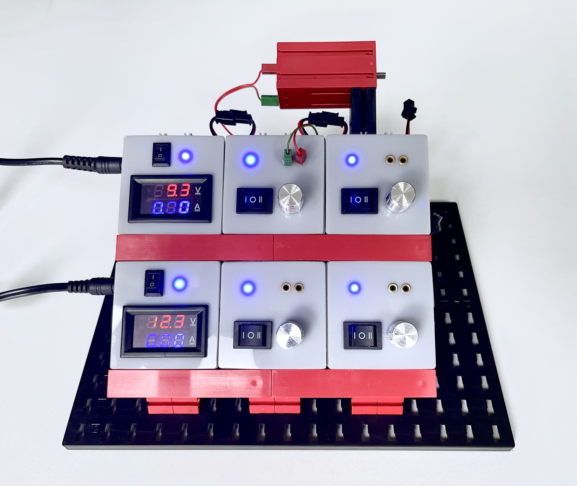
This method of mounting came in handy with the simple power supply module in 'Silberling housing' described elsewhere in this issue. The video I made of that project also shows the customization of these cable lugs.
The 2.5 mm 'Flachstecker', introduced by fischertechnik in 1967, has far from disappeared from the scene. Although the Dupont system can be an excellent replacement for most applications, it is nice to know that compatibility with classic connection methods is guaranteed in several ways.
The discussed PTN2-10 cable lugs seem easier to use than the ferrules and hollow rivets. They take up less PCB space because they require a much smaller solder island. From a cost perspective, at a price of about 3 cents each, they obviously leave the traditional 'Bundhülzen' (easily 15 times as expensive!) far behind. And although I will probably prefer the Dupont headers for future projects (especially in relatively small housings or with microcontrollers), it is nice to know that where necessary the traditional fischertechnik plugs can be used well into the future, also for those who do not want to reserve a substantial part of their crafting budget for simple passive components such as 'Bundhülzen'.