After designing and printing the 3D case and developing a universal interface and power supply, it was time to process all the new insights, wishes and ideas since the prototype of this module.
On this page more about the development of the Zauberling version 0.2. It now has some extra push buttons, four inputs and outputs with different power levels. It is switchable between positive or negative logic and equipped with a small screen for optimal feedback to the user.
Due to its versatility and configurability, the Zauberling is a so-called 'drop-in replacement' for any traditional Silberling. With its programmability, setting options and power outputs, it goes even further.
Because the module is freely programmable, it also allows the functionality of the small configurable electronics modules such as the E-Tec Module (fischertechnik no. 108227), Electronics Module (fischertechnik no. 152063), the Robotics MiniBots Module (fischertechnik no. 156499) available and combinable with the Silberlingen.
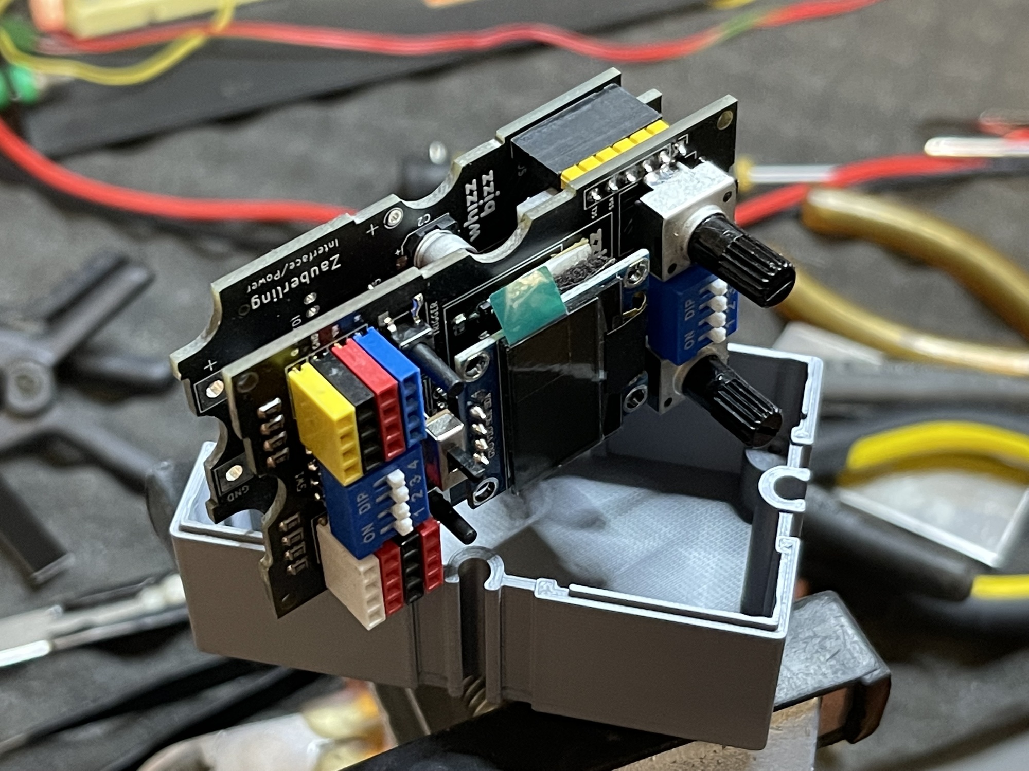
Naturally, this quickly led to the wish to make several copies of this flexible module. However, building the prototype of the Zauberling was quite labour-intensive and new insights and ideas were already emerging. In order to make optimum use of the limited interior space in the case (only 40x70x25 mm), I decided to make a universal power supply board that can also make the programming interface and I2C bus available. The main PCB of the Zauberling (or anything else I could think of after that) could then be slided on top as a 'sandwich'.
It was high time for a list of wishes and ideas for the next generation of Zauberlingen:
A Zauberling can bend to his present task like a functional chameleon. But when using several such modules in a project, one could quickly lose the overview. In principle, the same problem occurs with all modules that are configurable with DIP switches (such as fischertechnik's own E-tec or Electronics Module) and do not give any further feedback about their inputs, outputs, behavior or functionality.
A bunch of LEDs on the front of the Zauberling takes up a lot of space, and will of course only partially solve the problem; when troubleshooting, they do not yet provide a definitive answer about the set functionality of the relevant module. A small display would therefore be a nice extension. In addition to clear feedback about the inputs and outputs, all kinds of useful other (textual!) information could also be displayed on this.
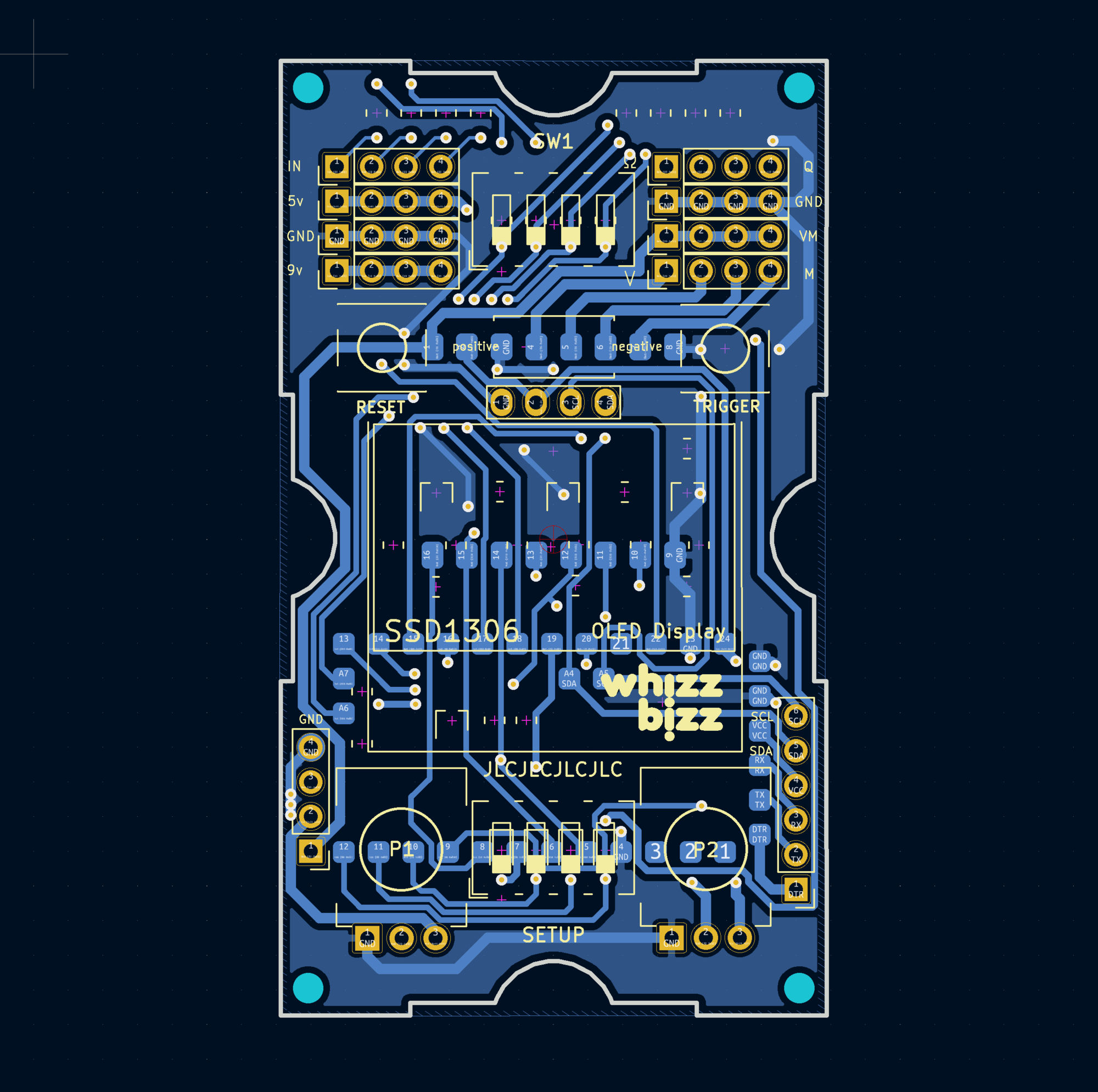
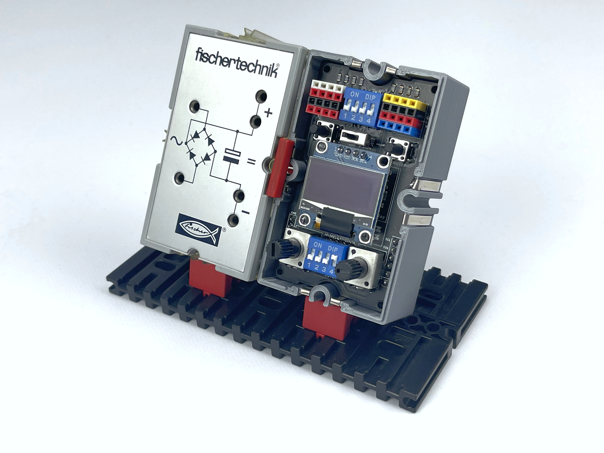
Once I had removed the sockets for connecting the traditional fischertechnik plugs from the front, with the necessary sliding and puzzling, there was room for a small display. Since ports A4 (SDA) and A5 (SCL) were already reserved for making the I2C bus available, the choice for an I2C display was an obvious choice. The display SSD1306 with 128X64 OLED pixels on ~2.5 cm (0.96 inch) screen diagonal already offers sufficient opportunities for feedback.
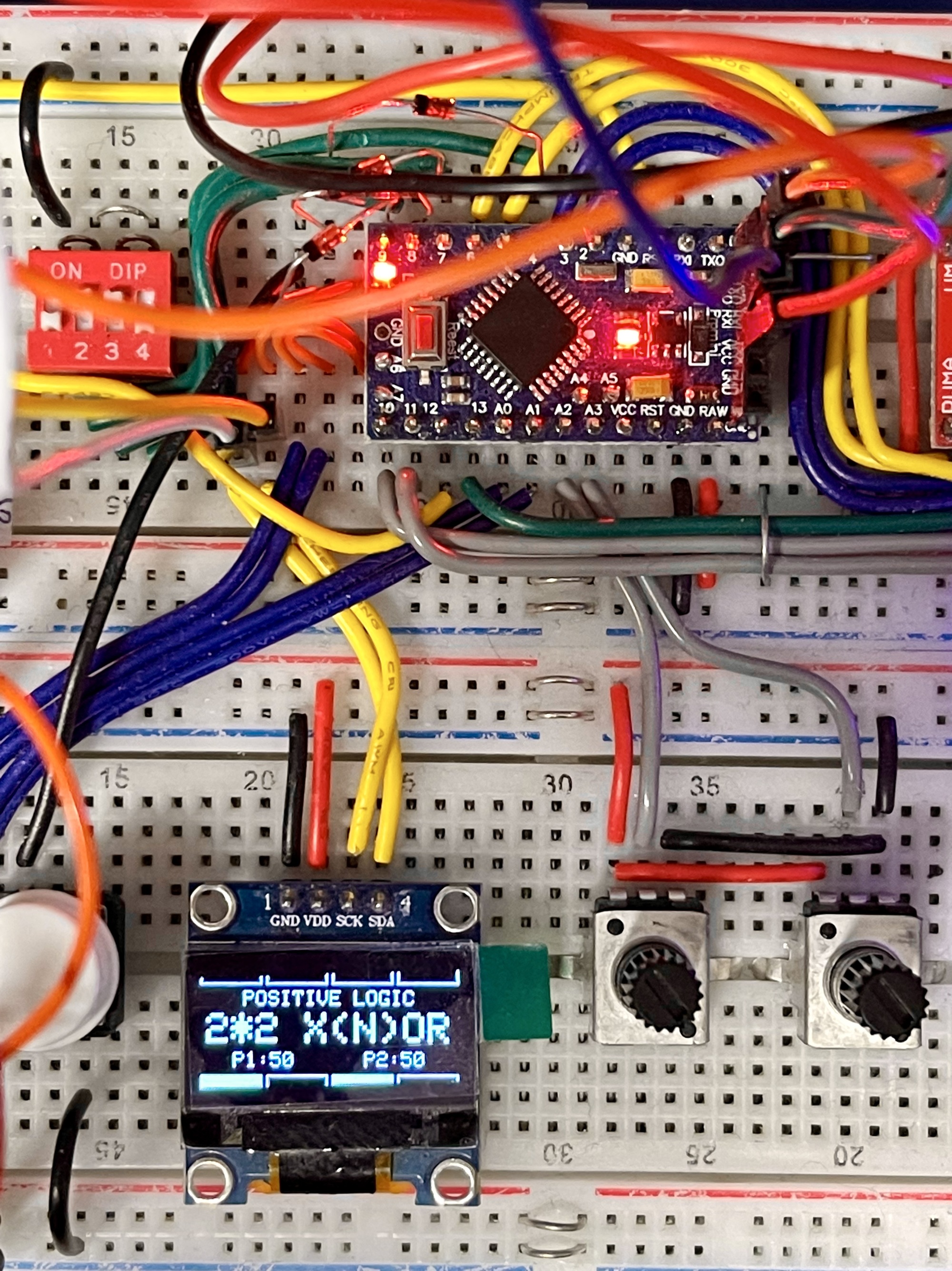
When experimenting and testing the new Zauberling on an experiment board, a few limitations came to light:
Until now, the enormous advantage of a readout on the Zauberling easily outweighed these obstacles in practice. In addition, it is always possible to omit the use of the display on the respective Zauberling for specific applications. And perhaps it will be useful in the future to explore how the display, perhaps more limited and less graphical, can be used without the relatively large claim on the processor's SRAM.
The design involved weighing the use of the Arduino Pro Mini's analog inputs on a gold scale. However, I dropped the idea of saving inputs/outputs by reading out the DIP switch for the configuration with one analog input (see concept here or here). Because I wanted to take the I2C bus (A4/A5) outside, there were only six analog inputs left for the two potentiometer settings and the four (analog) inputs.
With this, all entrances and exits had been used, while the coveted 'universal trigger' push button on the front of the Zauberling had not even been realized yet. Fortunately, with a bit of puzzling, I managed to make it functional. The DIP switch for setting the functionality is only read out once during the initialization phase of the Zauberling. With the 'Trigger' push button, all switches of the DIP switch are pressed 'active' simultaneously (DIP setting 15) via a 'logic OR' (with four diodes). This allows this 'Trigger' push button to be detected neatly. The only limitation, of course, is that the 'Trigger' push button cannot be used with initial function selection 15 of the DIP switch. Because such an extra push button is not necessary for every function, this seems no problem at all.
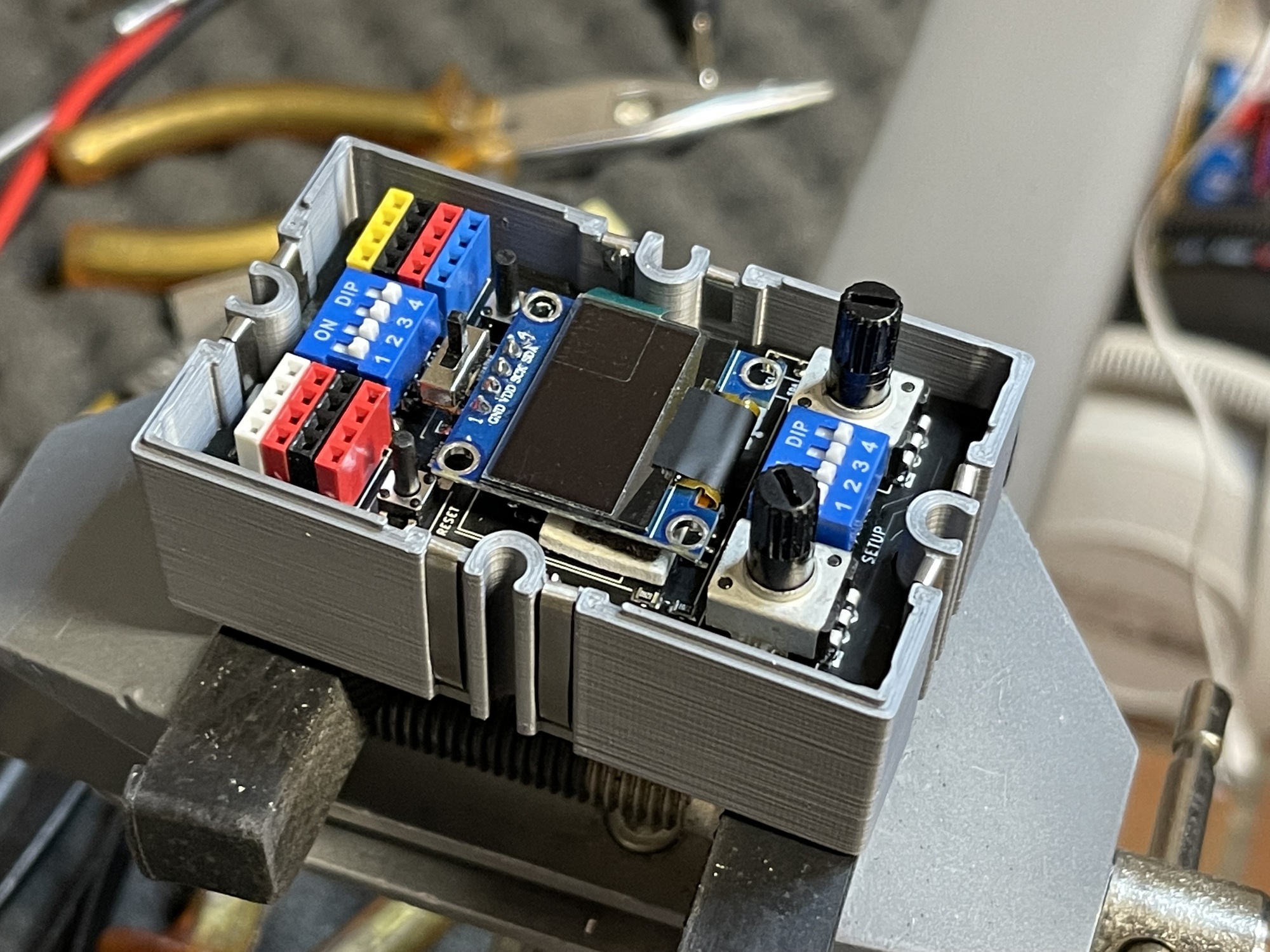
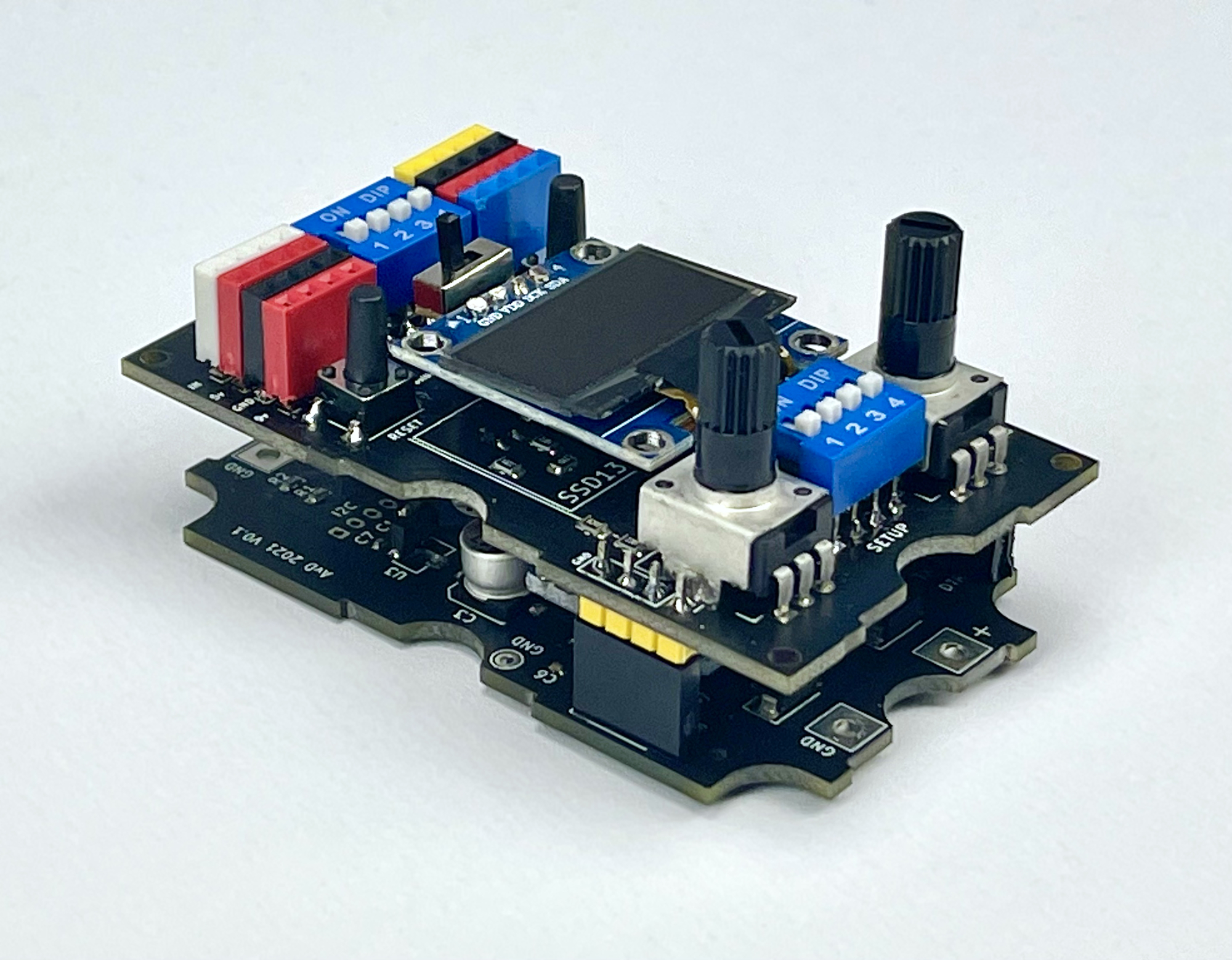
The servo connections have been removed. The four analog inputs can individually be switched between resistance or voltage measurement with a DIP switch. The function selection DIP switch is read during the initialization of the Zauberling for the function setting, and can then be bridged during the program with a push button with the 'Trigger' button on the front. The choice for positive or negative logic can be made with a slide switch.
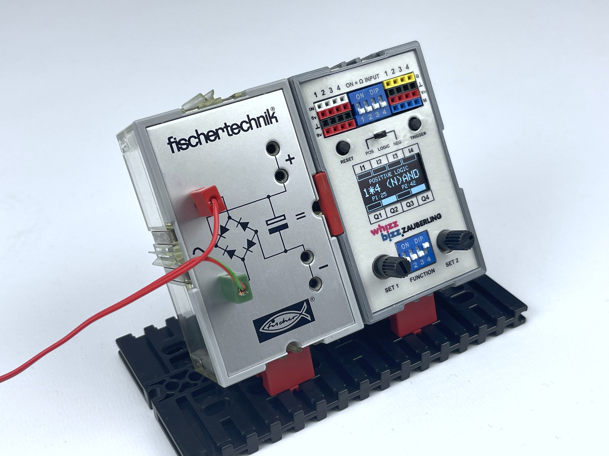
There is also a RESET push button on the front now. Two potentiometers are now available on the new Zauberling for setting thresholds or other analog configurations. The digital outputs controlling the motor outputs are available buffered at 9 volt Silberlingen level. These signals are linked and cannot be controlled separately, but this can even be an advantage in some experiments.
The current function of the Zauberling and other configuration (such as the choice of positive or negative logic) as well as the status of the inputs and outputs are visible on the display. Specific information per function (such as a counter or the descending time of a mono-flop) can also be displayed here.
For connectors on the front so-called 'female header connectors' are used now. These make it easy to make the different supply voltages available on the front as well. Handy, for example, for simply supplying active sensors with a power supply (with one plug, such as with a servo).
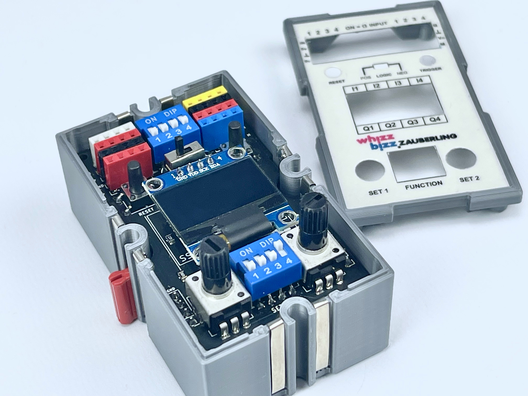
The starting point when designing the main board of the Zauberling was that the connectors that connect to the signal and power rails of the power and interface board are in the right place on the PCB. But after making a usable arrangement of the components that determine the layout of the front, there was little space left to place the other necessary components on the (small) double-sided PCB. It soon became clear that SMD components should be used wherever possible, so that the two sides of the print could be used optimally.
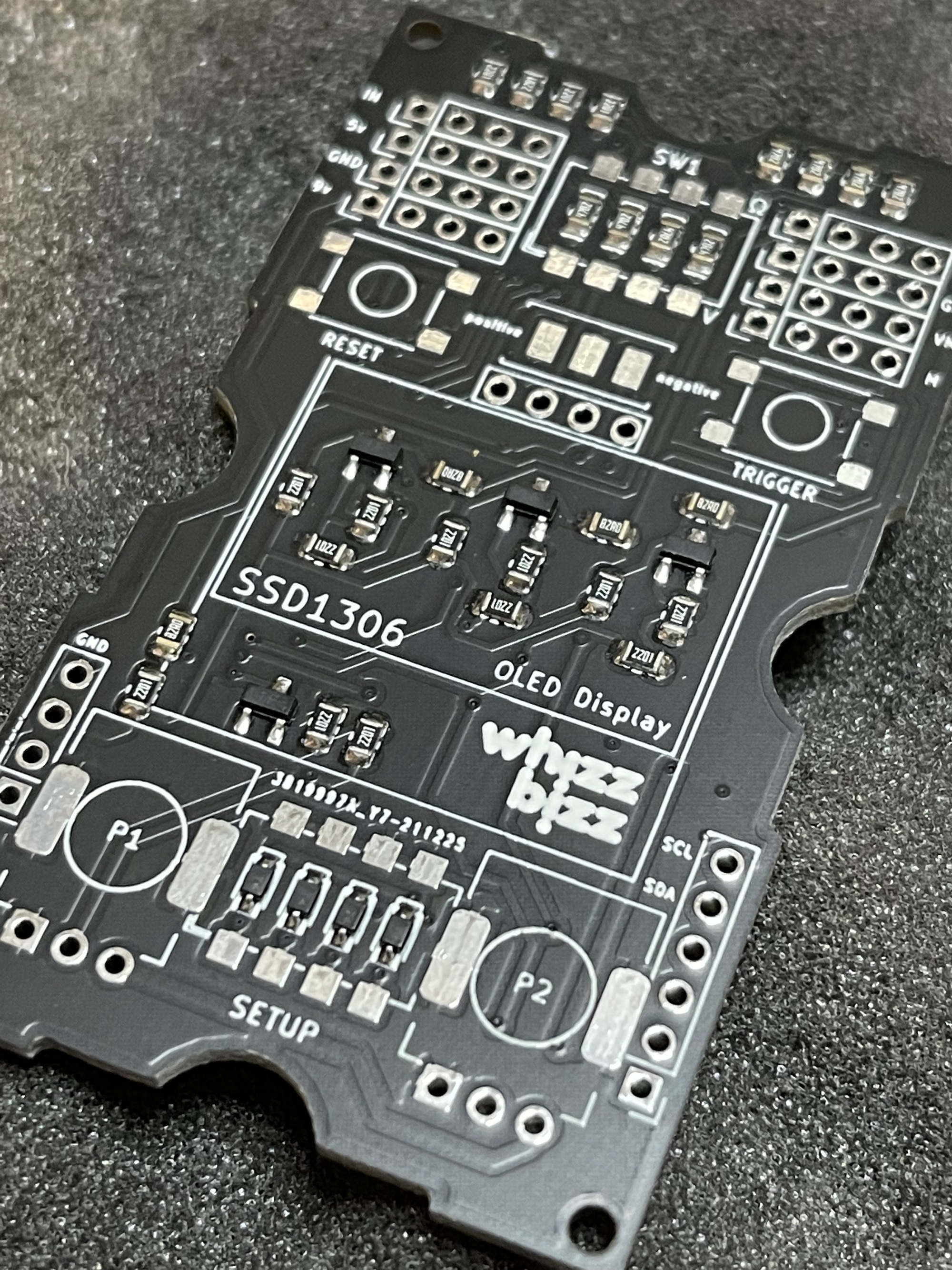
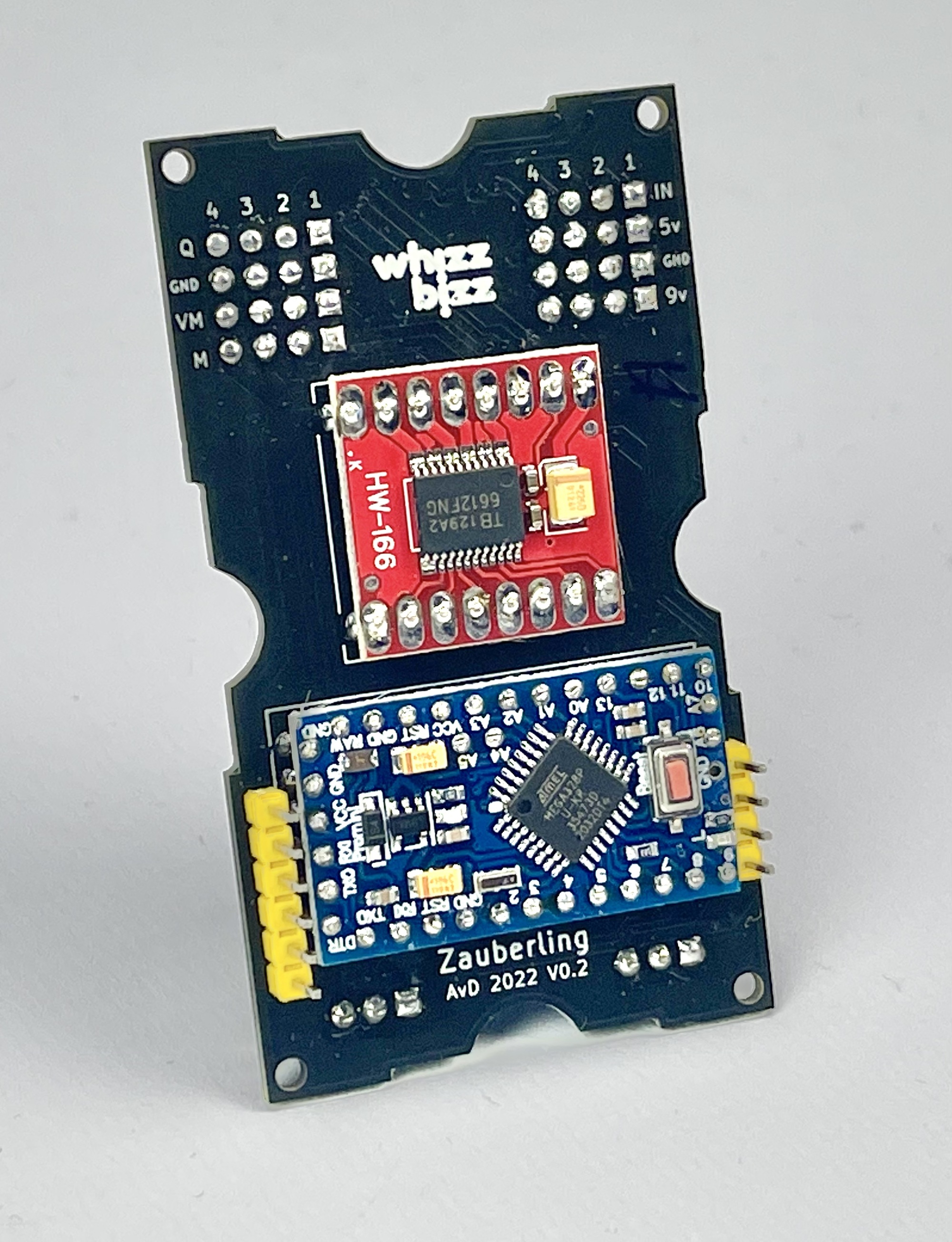
Both the ATmega328 microprocessor and the TB6612FNG motor driver are of course available in SMT (Surface Mount Technology) technology, but for both components I eventually opted for a complete board/module. These were more readily available and, oddly enough, even cheaper. And because in this case it was a small series of semi-prototypes, it seemed to me that the advantage of even more PCB layers for the copper traces outweighs the 'piggy-back' mounting of these small boards on a series of undrilled SMT copper islands.
By soldering header strips to the SMT islands and then cutting them off, mounting is very easy in practice. The photos show how the components are mounted on both sides of the PCB. The multi-layered main PCB is in turn merged with the power supply and interface PCB, which is mounted at the bottom of the case. As a result, the resulting 'sandwich' makes optimum use of the limited space in the case, also in terms of height.
At the bottom of the Zauberling's screen, depending on the selected function, either the four digital or the two motor outputs can be monitored. Strips are shown for a motor function, in which the position and length of the bars reflect the output voltage and direction of rotation.
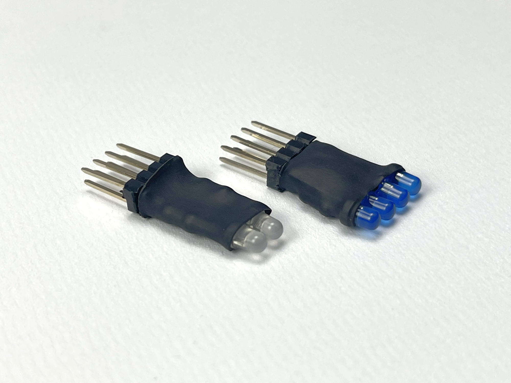
For some applications it may be useful to use both output types. For example, to have a digital signal available that indicates the direction of rotation of a motor. For a quick overview of the output signals, a few 'output indicators' with LEDs (with series resistor), which can be plugged directly onto the outputs, offer a solution. One gives a good look at the digital output signals, the other contains two bi-color LEDs that make it easy to read the rotational speed and direction of a motor output.
The basic Sketch for the Zauberling can be downloaded from GitHub. The various functions of the Zauberling can be set with the 'Function' DIP switch. After making changes to the configuration, a short press on the RESET button on the front is enough to use the next function. Twelve useful functions and one engine demo sequence are available as standard.
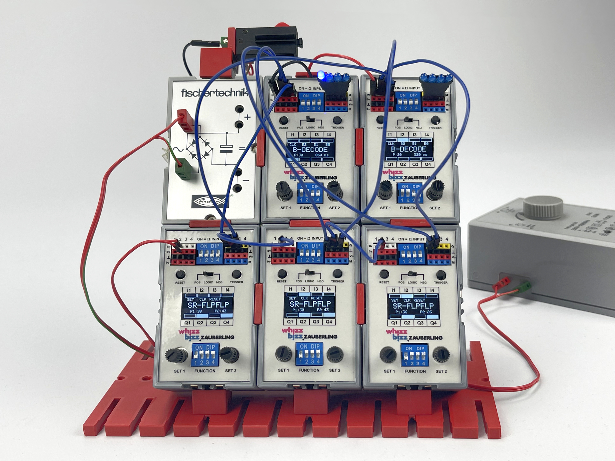
With Flip-Flops that act as a 3-bit binary counter and two Zauberlingen that decode this binary number again, the next LED in the series lights up with each press of the button. A nice proof-of-concept for some basic functions, but not really something that adds much to the digital functions of the traditional Silberlingen. In fact, these will easily rival the Zauberling in terms of speed with their lightning-fast parallel operating discrete electronics.
But the Zauberling obviously comes into its own as a PLC (Programmable Logic Controller) for process automation or for adding specific functions that can simply never be made with the Silberlingen. Its strength lies in its programmability and collaboration possibilities with the traditional Silberlingen.
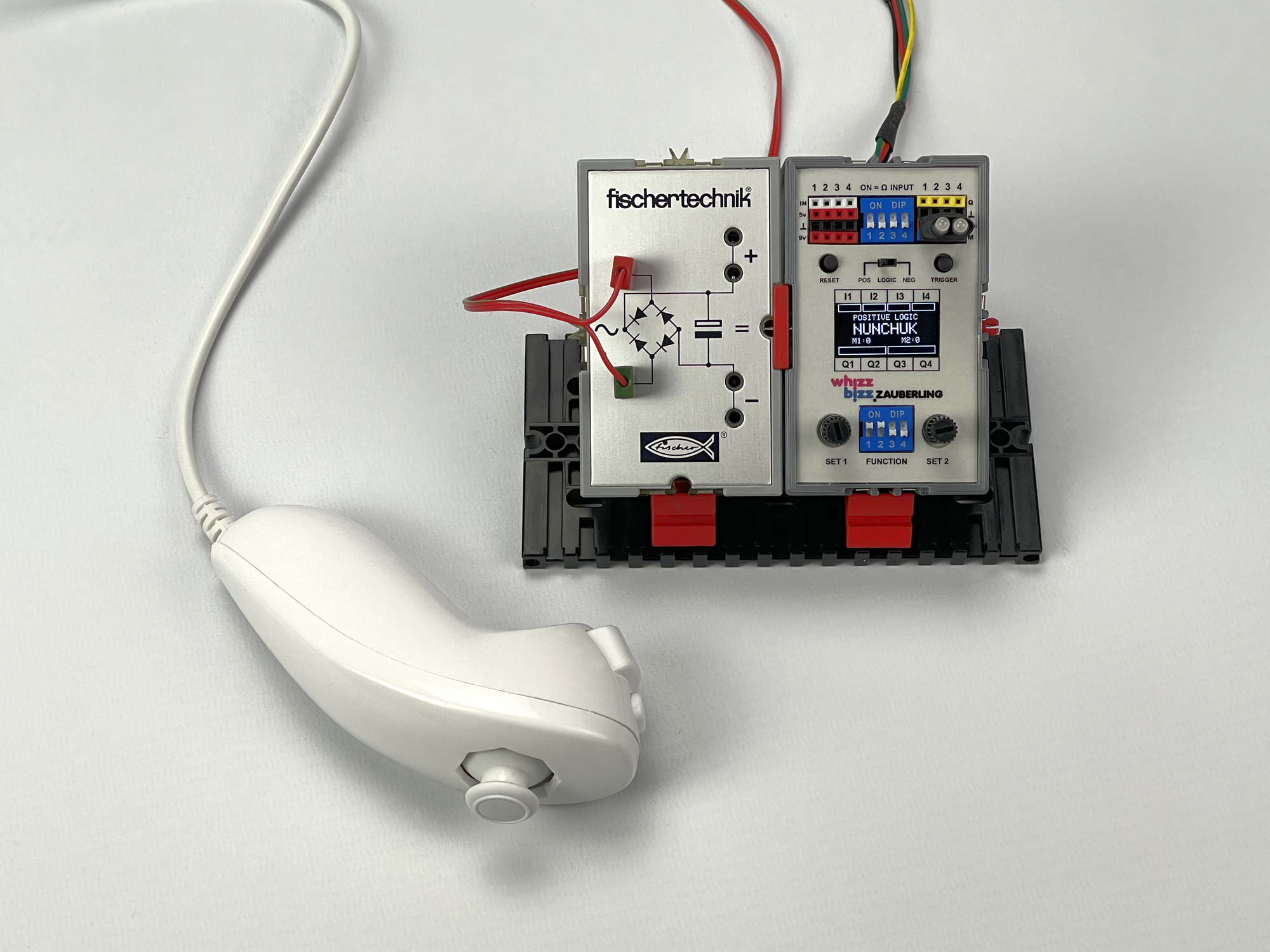
The addition of the I2C bus makes it possible to use the Zauberling with all kinds of external sensors. As a preliminary exploration in this area, I already tried out a few applications. It turned out to be quite easy to control two motors with a so-called Nunchuk (hand controller). Both the Nunchuk and the motors can be connected directly to the Zauberling. The status of the push buttons, or the acceleration/position information of the Nunchuk could be communicated via the I2C bus for processing by other Zauberlingen or specific I2C modules. For example, I experimented for a while with an I/O expander (PCF8575 or MCP23017) that could be build in a separate Silberling case in the future.
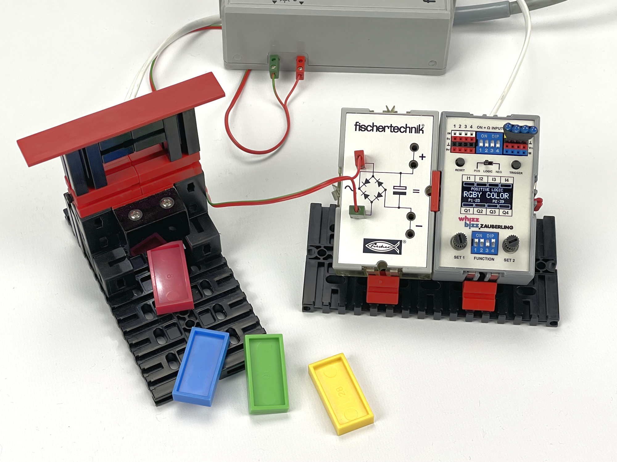
I did a second I2C sensor experiment with the color sensor TCS34725. Outputs 1 to 4 are activated respectively when a red, green, blue or yellow domino is detected. This makes it possible to create an automatic color sorter.
The I2C bus enables additional inputs and outputs, communication, the connection of sensors or the control of servos or stepper motors. Versatility that encourages one to check out some old construction examples from the Hobby4 book series and control them with modern technology. Plenty of material for experiments with the Zauberling for the future, so... to be continued! 😉