
Small circuit boards with a wide variety of sensors can be purchased online for very little money. These sensor modules are primarily designed for use with 5 volt microcontrollers but less easily used with the fischertechnik electronics modules and classic “Silberlingen” that are in the 9 volt domain. The adaptor board discussed here was designed to improve the compatibility and application possibilities of these sensors. It facilitates the rather different pin order of the 3-pin connectors of the various boards. It also provides the (lower) supply voltage for the sensor board and allows working with 2.5 mm fischertechnik plugs.
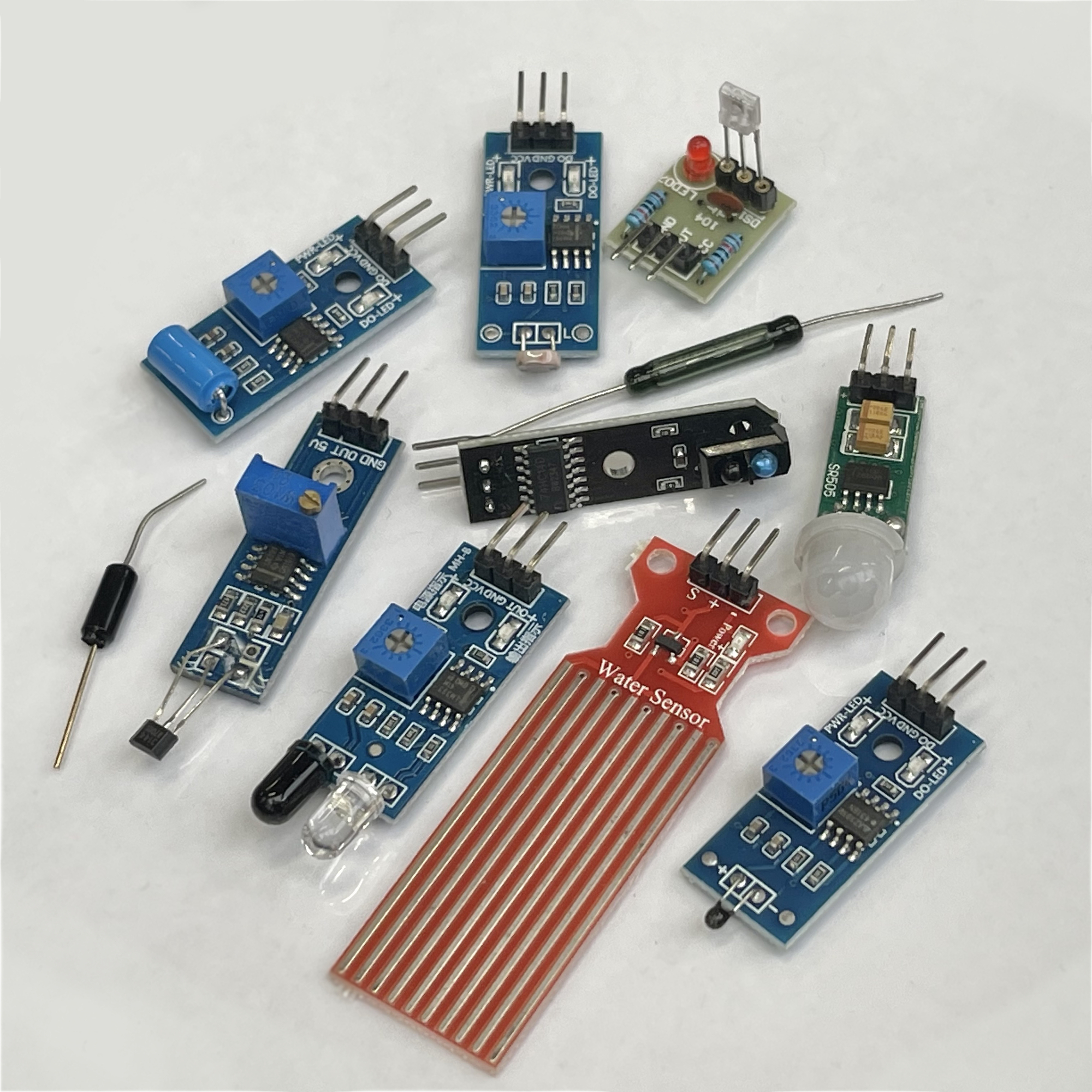
The sensor boards pictured here are designed for use in projects built with universal microcontroller boards such as the Arduino, micro:bit, ESP-32 or Raspberry Pi. Among others, the photo shows a PIR motion, temperature and humidity sensor. The passive reed switch and vibration sensor are also available as boards on a board with 3-pin plug. The sensor boards are offered at low prices and are too much fun not to play with.
Connecting to an Arduino is relatively easy. There are countless success stories of this online. But as you know, I like to tinker with fischertechnik. Therefore, I thought it was time to investigate which modifications would be useful to make these sensor boards easier to use with fischertechnik's own TX and TXT controller or the classic 'Silberlingen' electronics modules. In doing so, we are in fact running into some incompatibility hurdles.
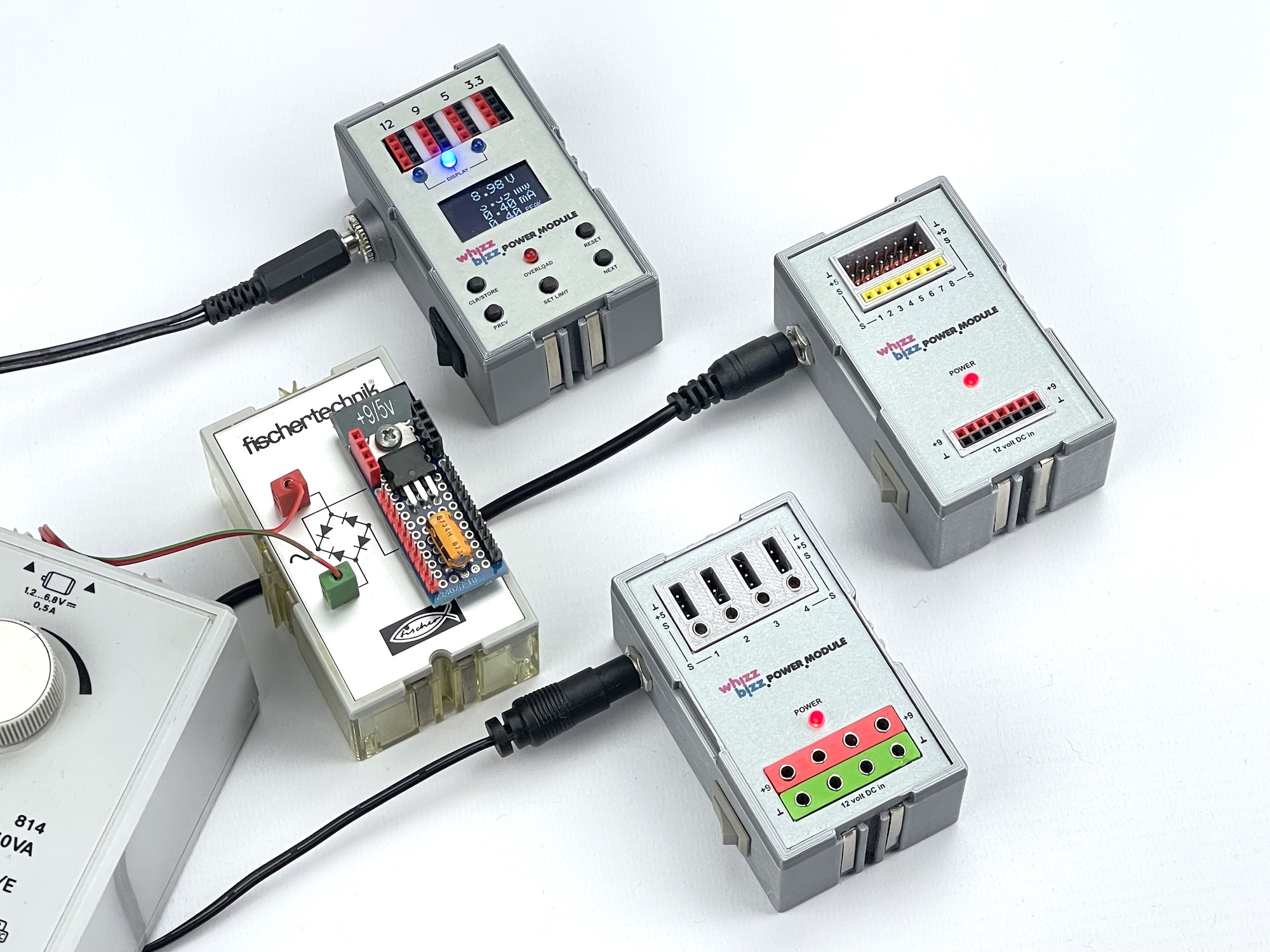
Without exception, these sensor boards require a supply voltage of 5 volts. In the past I investigated how Hall effect, LDR, touch switches and infrared obstacle sensors could be made usable according to this principle. In order to provide the 5 volt supply voltage, I designed some power supply modules for this purpose (picture opposite).
Once the 5-volt supply voltage is available, the sensor boards may be used on the inputs of regular microcontrollers and the TX and TXT controllers. For use of unmodified boards with the 'Silberlingen', however, we still need to connect a so-called 'Grundbaustein' in between to make the output signal level detectable.
Another possibility is therefore to make the sensor boards suitable for a supply voltage of 9~11 volts, which can be obtained directly from the TXT controller or from the 'Silberlingen'.
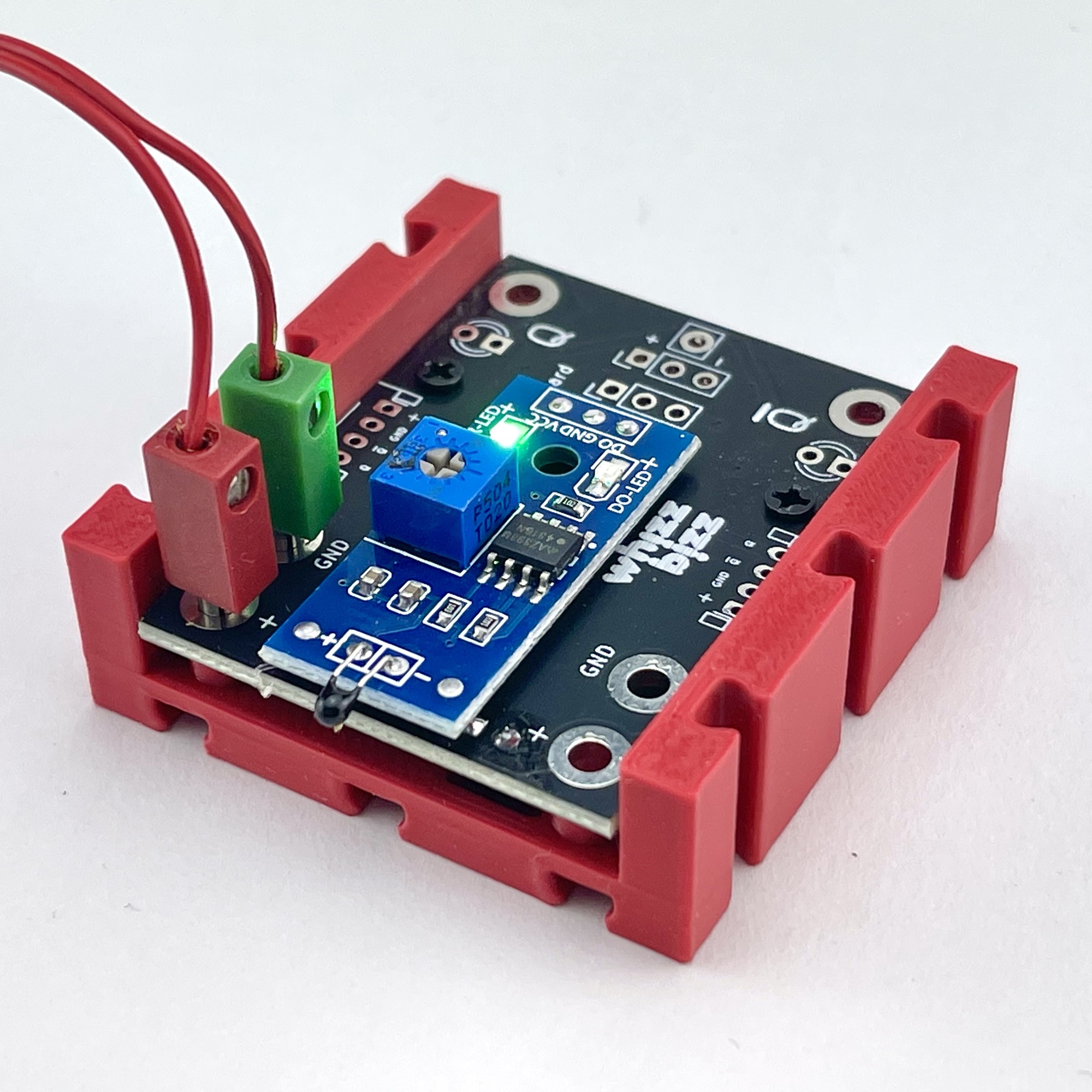
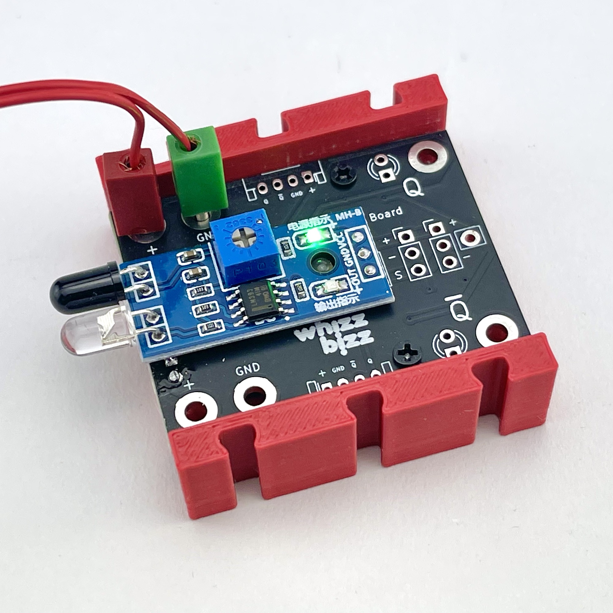
Some sensor modules, such as the IR obstacle sensor, are equipped with an LM393 comparator for a sharper (sometimes adjustable) detection level and less noise around the detection threshold. The LM393 can handle a supply voltage of up to 36 volts, so in theory it could be used directly on a higher supply voltage without problems. The problem, however, is that the series resistors of any mounted indicator (and/or IR) LEDs are obviously not matched to this. Without adjustments, these are therefore very likely to burn out within the foreseeable future at this operating voltage.
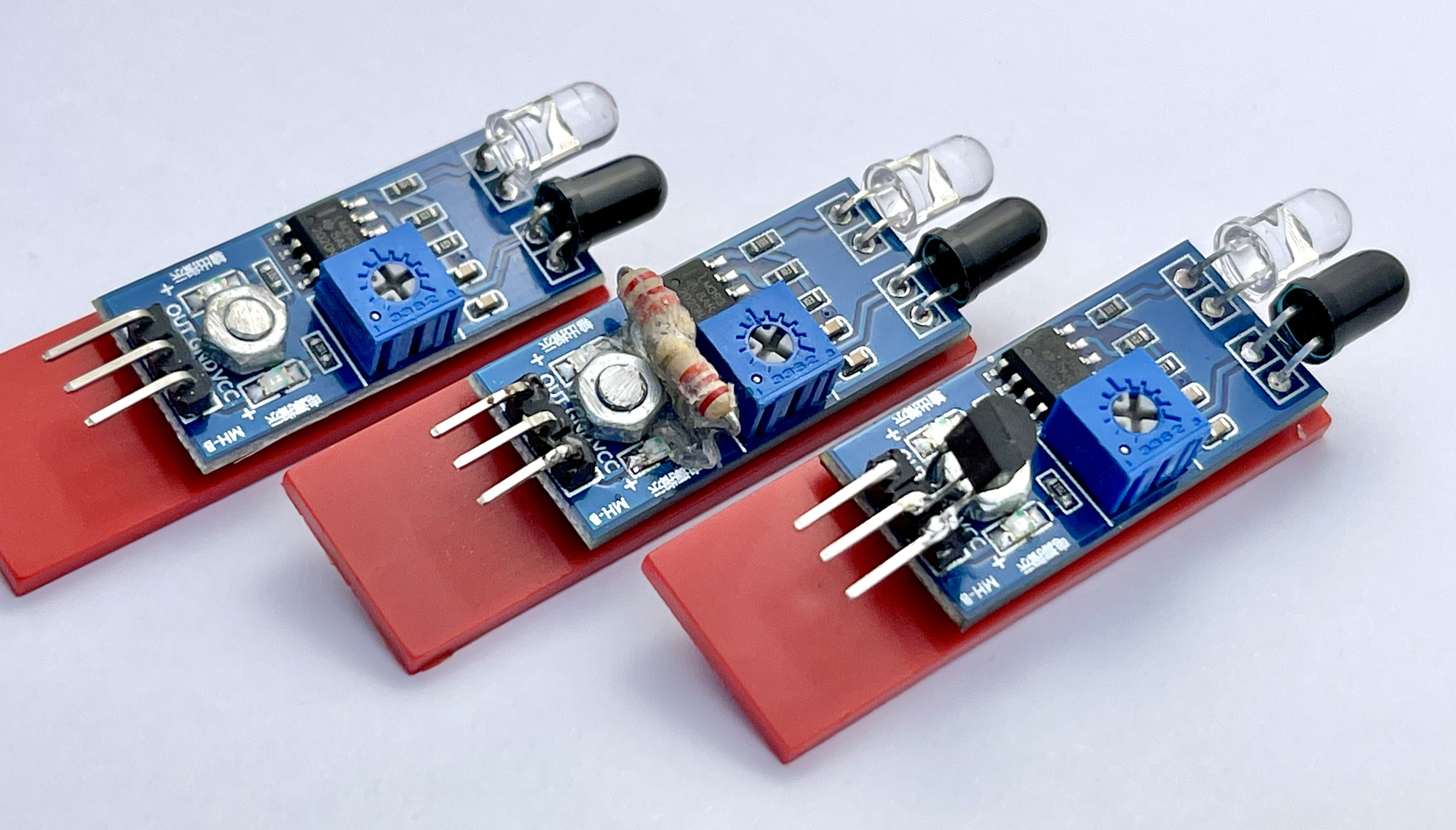
Some possibilities for adapting obstacle sensors for use on 9 volts have been explored by me in the recent past. The image to the right shows some of these experiments with IR obstacle sensors. On the left a module whose ballast resistors (smd) have been increased, in the middle one where this has been done with normal resistors and on the right a solution where a 5 volt voltage regulator has been soldered on. However, the outputs of these modified sensors are still not electronically compatible with the 'Silberlingen' so it remains necessary to switch a 'Grundbaustein' per sensor in between.
Those who want to use the various sensor boards usefully without a microcontroller will also have to consider incompatibility between the output and input signals. Microcontrollers often have sufficient inputs with a high input impedance. These inputs draw very little current and actually only sample the voltage level offered by the connected sensor output. Whether a logical 'high' or active signal is represented by +5 volts, or just 0 volts, is even irrelevant here. After all, the logical interpretation ('positive' or 'negative' logic) of the physical voltage levels of the output can easily be adjusted in the software.
The classic fischertechnik electronics modules, such as the 'Silberlingen', however, require a current-switching input signal at their inputs. These modules are electronically constructed according to the so-called diode-transistor technique. A consequence of this is that the 'Silberlingen' use so-called 'negative logic'. Here, for a logic '1', the input signal must be pulled through the input to zero volt level. The outputs of the sensor boards cannot do this. Their logical output signal is represented by a voltage level that is unable to pull the input of a 'Silberling' to adequate zero level.
So it would be more practical if the sensor boards had 'power outputs'. This would not disturb the usability for modern microcontrollers, but would also make them usable for use with the 'Silberlingen'. It would then even become possible to use so-called 'wired ORs'. And if each output signal is also available inverted, the mix of 'positive logic' and 'negative logic' is easier to make.
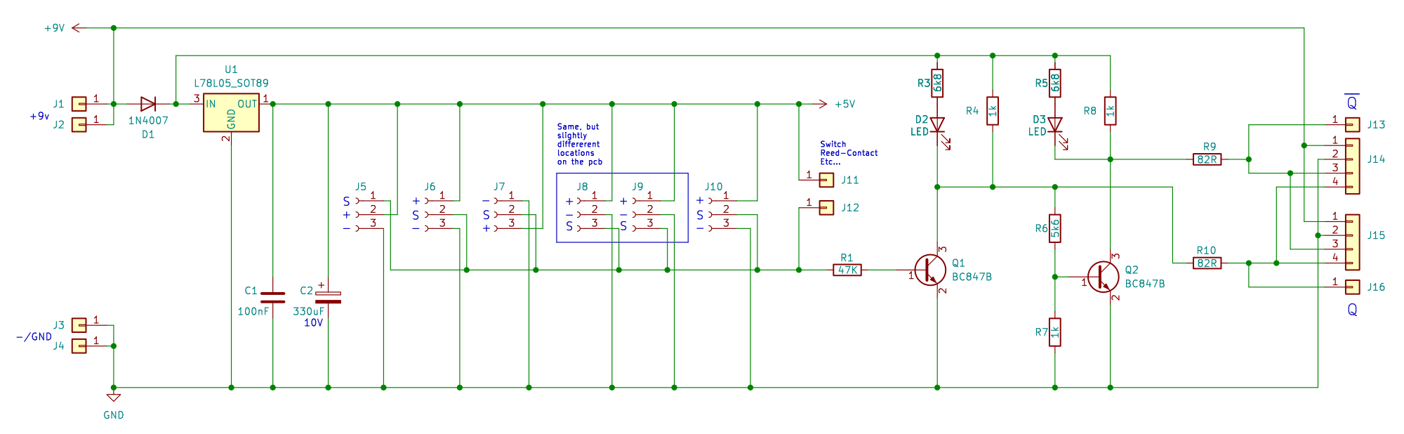
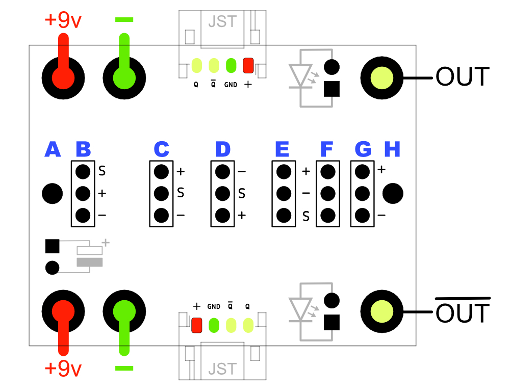
The schematic above shows the universal adaptor board with which all the above requirements can be met. To ensure optimum compatibility with the'Silberlingen', the original design of output stage with inverting continuation stage was taken as a starting point.
The small resistance of 82Ω at the outputs appears to be a simple current limiting device as a protection against directly connecting an output to the positive supply voltage. However, the Silberlingen originally used BC238 transistors with a maximum collector current of 100mA. This would mean that the output would be (briefly) “protected” up to a supply voltage of 8.2 volts. So the choice of the nowadays more common (and cheaper) universal NPN transistor BC547 in the homebrew 'Silberlingen' is a fine choice. It will not change the switching behavior of the modules while this transistor has an even higher maximum collector current.
The voltage of the output signal is approximately the supply voltage, and the whole thing, despite the voltage regulator, can still be used in practice usually from 5 volts. The schematic led to the circuit board design in Figure 5. For clarity, a 3-pin connector is shown here at every possible position. In reality, of course, only the position appropriate for the connected sensor is used.
If the sensor board does not already provide this itself, optional control LEDs can be mounted on which the outputs can be read. Power supply and connection of the output signals is possible via , or via the optionally fitted white JST connector(s). Since there must be cutouts in the side walls if landscape (angled) JST connectors are used, I designed two variations of the holder.
After mounting the PCB, the smd parts are located in the holder at the bottom. The holder includes a semicircular recess for the small radial electrolytic capacitor C2 on the underside of the board. This electrolytic capacitor is not necessary in practice and was only conceived to protect against an input voltage “polluted” heavily with noise, for example, by motors.
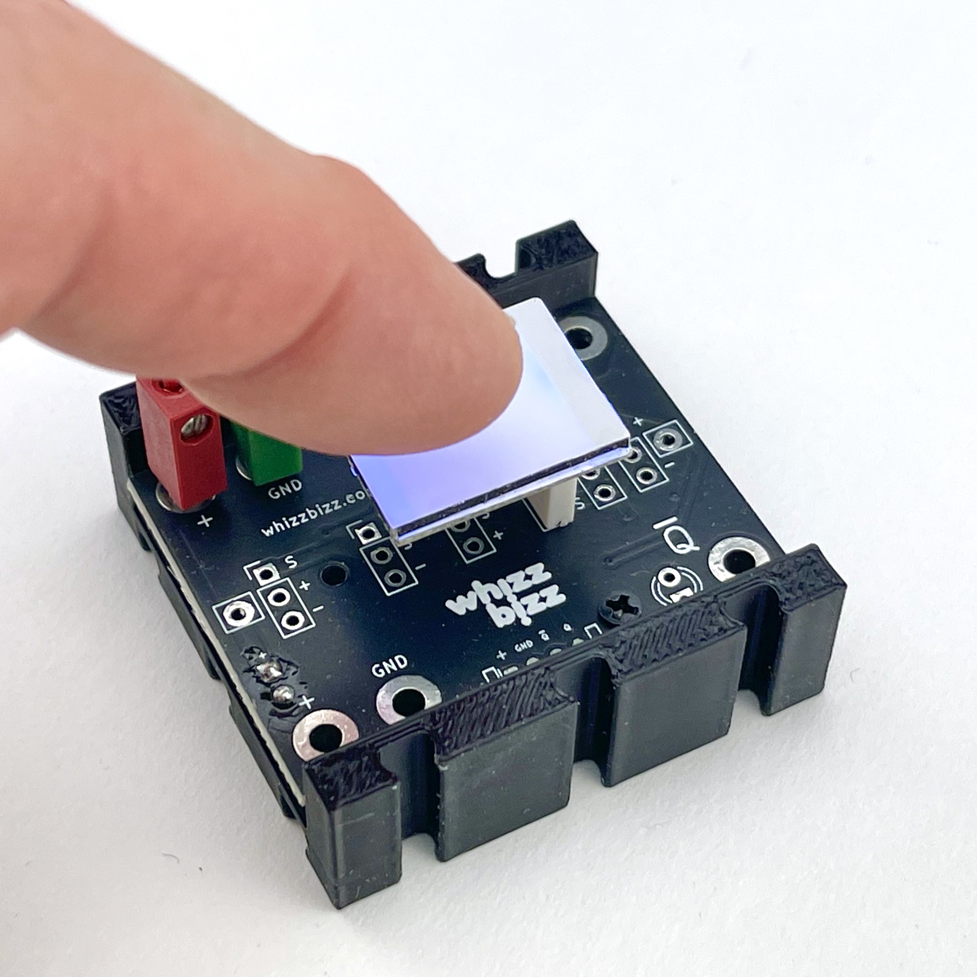
The photo on the right shows that the LED touch switch on the adaptor board can also be used. However, perhaps a somewhat less fragile housing will be designed for these touch switches in the future....
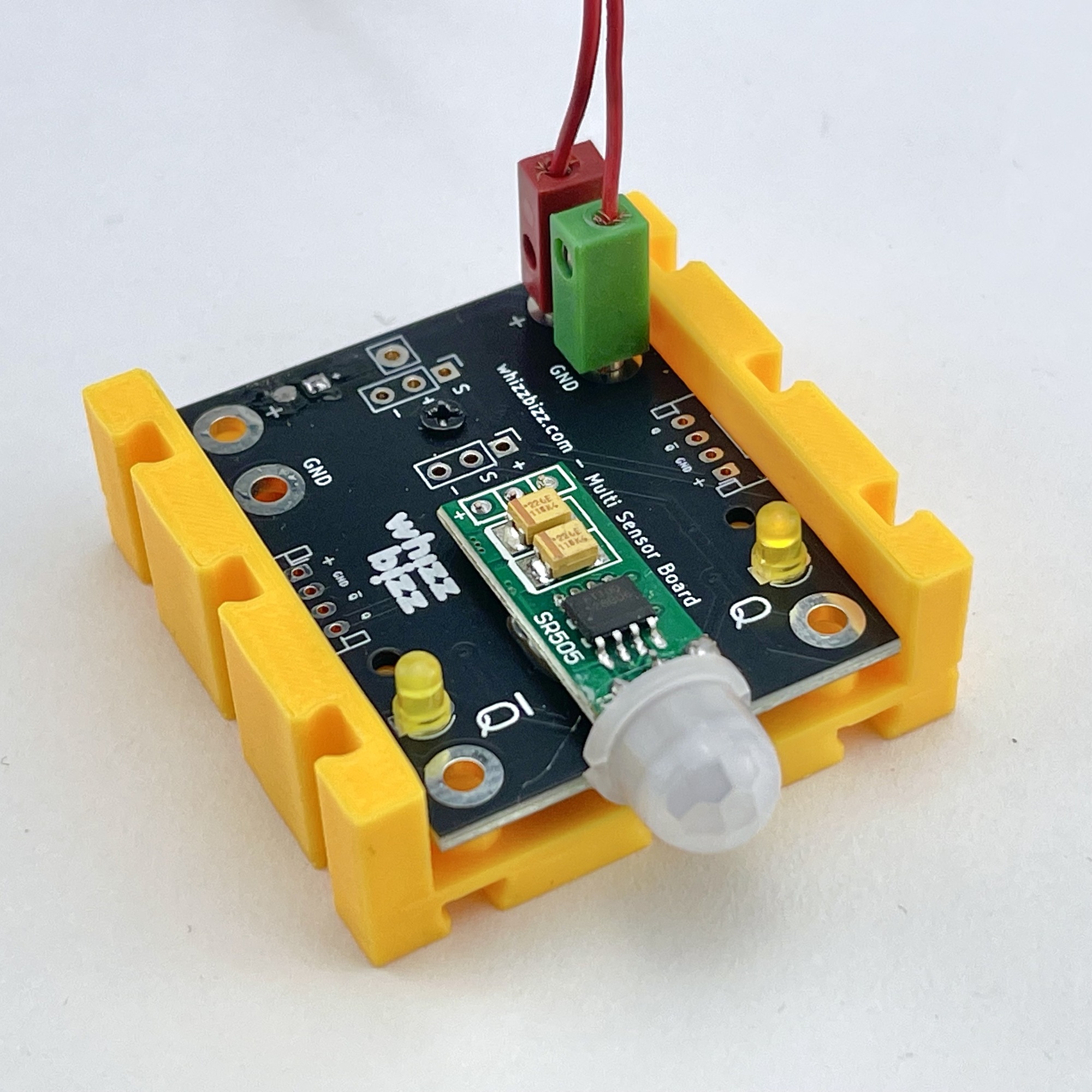
The sensor board of choice is simply soldered to the appropriate connection position. Sometimes a little preparation of the sensor board is required. As shown in the photo at the top of this page, many of these sensors come with, often angled, soldered-on 3-pin connectors. In that case, if no adjustment options on the top of the sensor board need to remain accessible, the sensor board can be plugged upside down into a 3-pin connector with the correct pin sequence.
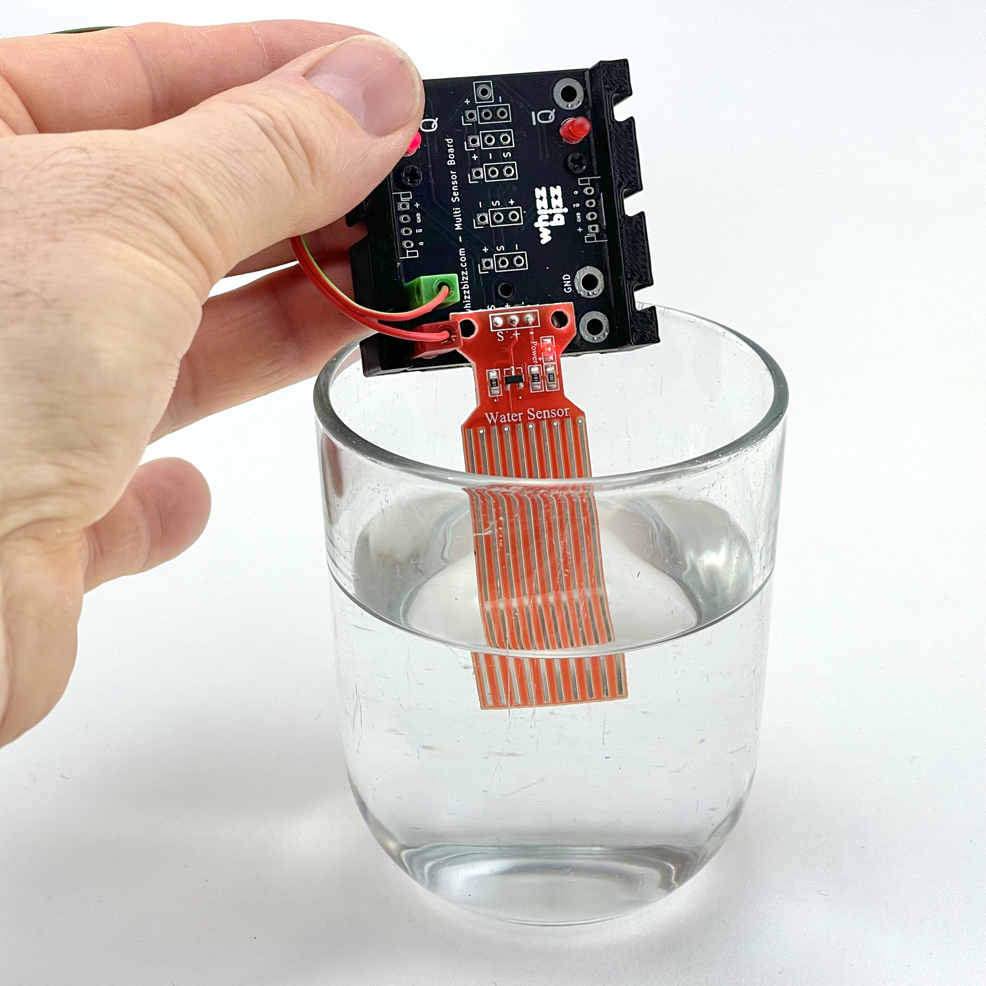
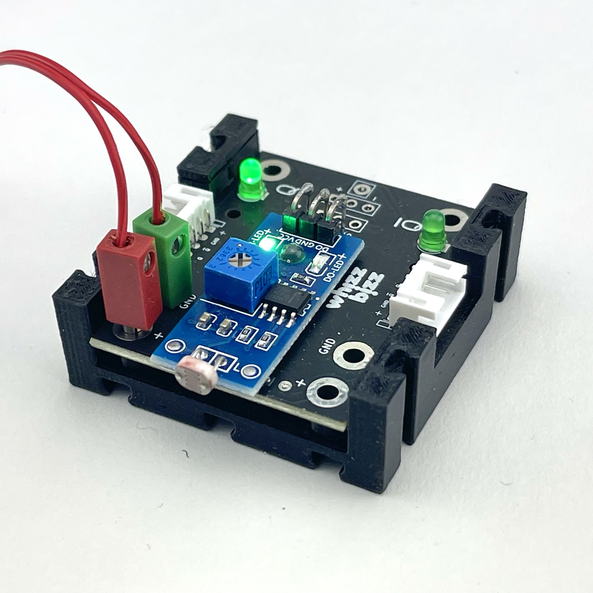
A little more work, but a neater solution is to remove the mounted connector and make the connection to the board with three short wires. For fixing the sensor board to the module board, I achieved good results with a glue gun for both mounting options. This way, even the water sensor (see photo) could be securely mounted.
The different connection options are shown to the right. The blue positions A through H indicate the possible connection points for the possible sensor boards. The optional electrolytic capacitor, which can be soldered to the underside of the board, is shown in gray. The LEDs at the outputs are also optional and therefore shown in gray. They are not needed if the sensor board used already has its own indicator LEDs. The power supply and output(s) can be connected with fischertechnik plugs in the corresponding connector holes in the board, if desired. These connection points are doubled so that several sensor modules can be easily looped through.
Plug connections that are too loose can be solved by carefully bending the blades of the plugs a little wider apart with a knife and not pushing the plug all the way through to the PCB.
Those who want to save on connection height or fischertechnik plugs, and who have the ability to make their own cords with JST-PH connectors, can optionally choose to use (one or) two upright and/or lying four-pole JST-PH connectors instead of the fischertechnik plugs. Three spots are available in the housing where the adaptor board thus equipped at will can be mounted with a small 6mm M2 screw.
Passive sensors, such as the vibration sensor, a loose reed contact or a (wired) push button, can be connected between positions A and H. The various three-pole terminals provide a range of connection options for the active sensor boards that require a (5 volt) power supply.
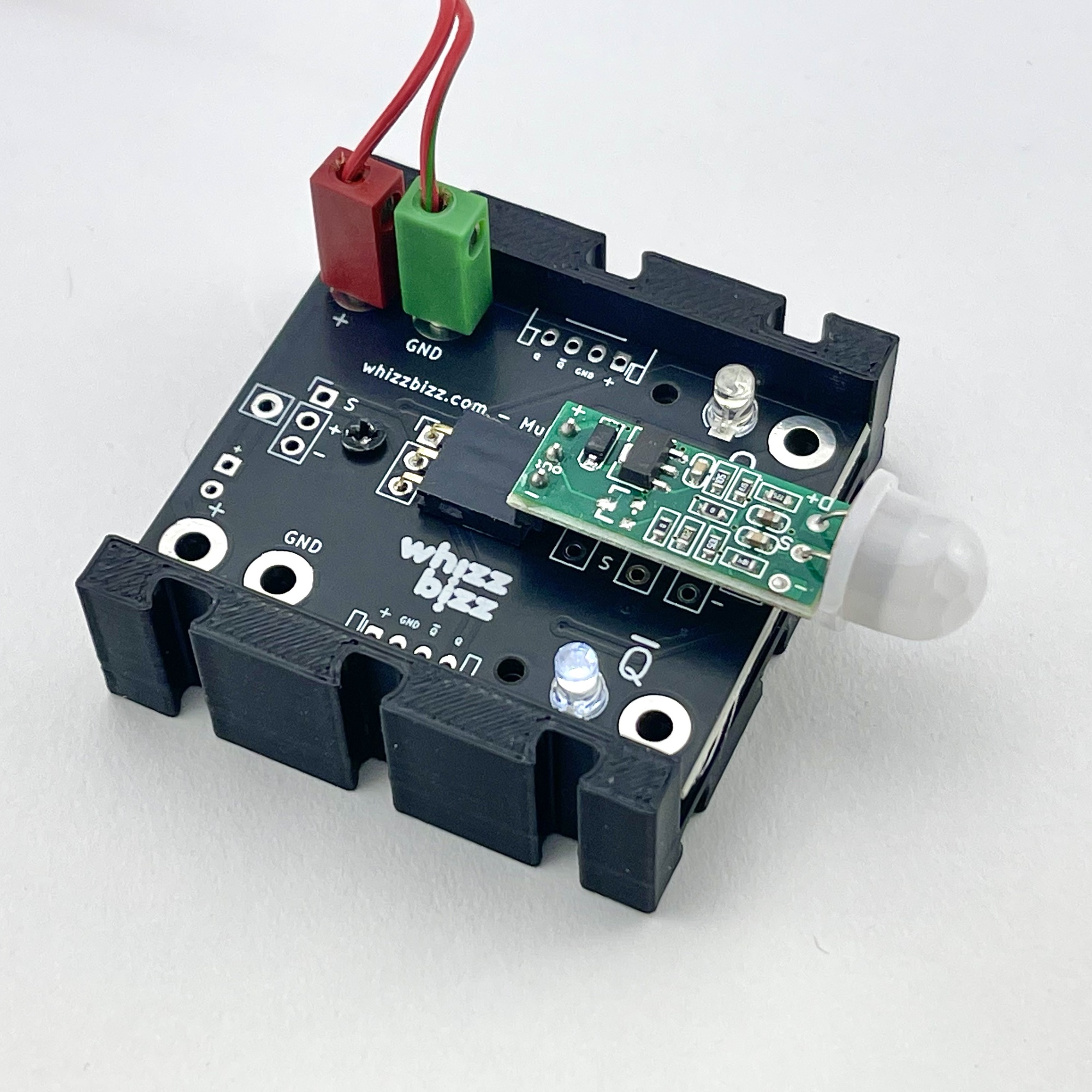
Connection option E can be used for LDR, IR obstacle and temperature sensor boards, as well as for the LED touch switches. Position F is basically the same, but the difference in position makes it possible to place longer variants of these sensor boards, or house the whole thing in a closed housing. This was also the correct connection location for the vibration/motion sensor board. I placed my Hall-Effect sensor boards at position G, while the humidity sensor could find a place at position B on the edge of the board (see photo). For the small PIR motion sensors, position D is the best choice, the sensor board then reaches exactly to the right side. But this sensor can also be connected upside down with a connector base at position C, for example (see PIR motion detector in first photo of the series above). In short, there is always a place for a particular sensor board on the adaptor board.
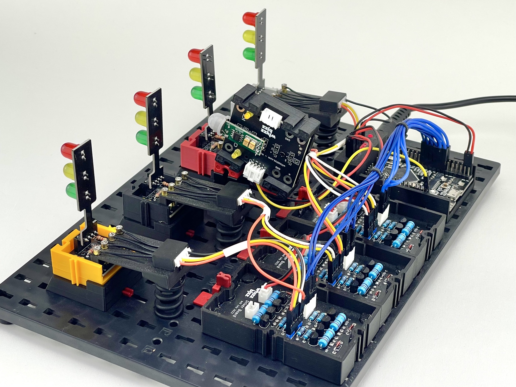
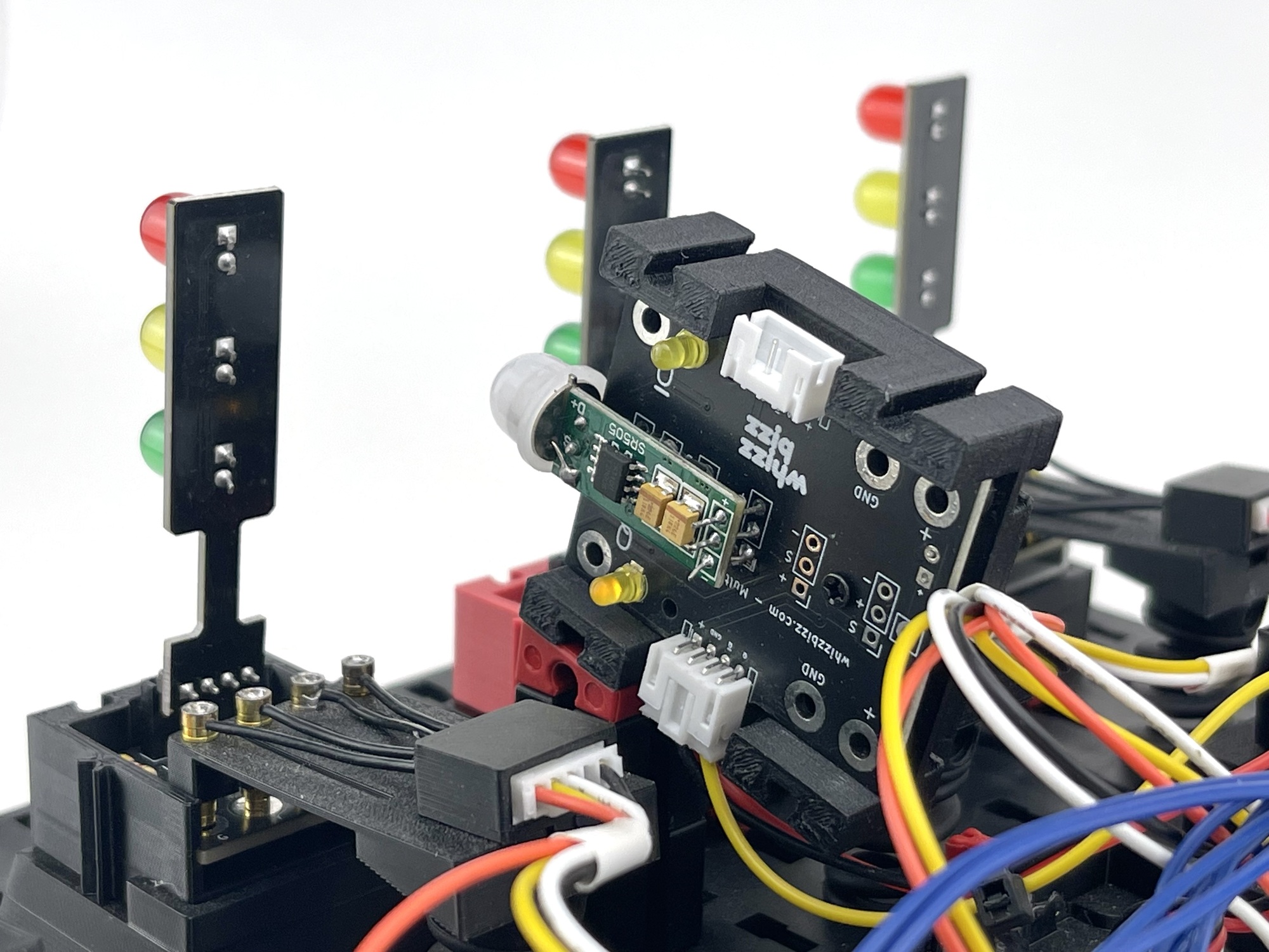
A module with a PIR motion sensor came in handy for starting a demonstration model with four LED traffic lights on command at the last meeting of the Dutch fischertechnik club. This model, visible below in the large photo, starts a small light show as soon as an interested party walks up to the table. This model is controlled with an Arduino Mega Pro Mini where the various LED traffic lights are powered via a few modules with short-circuit proof power outputs. But with the adaptor board discussed here, it is just as easy to build such a control with the TXT controller, or even with the traditional 'Silberlingen'.
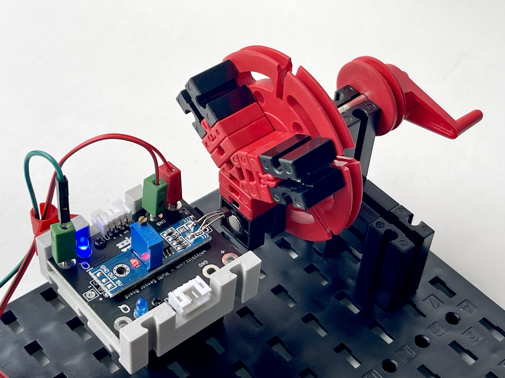
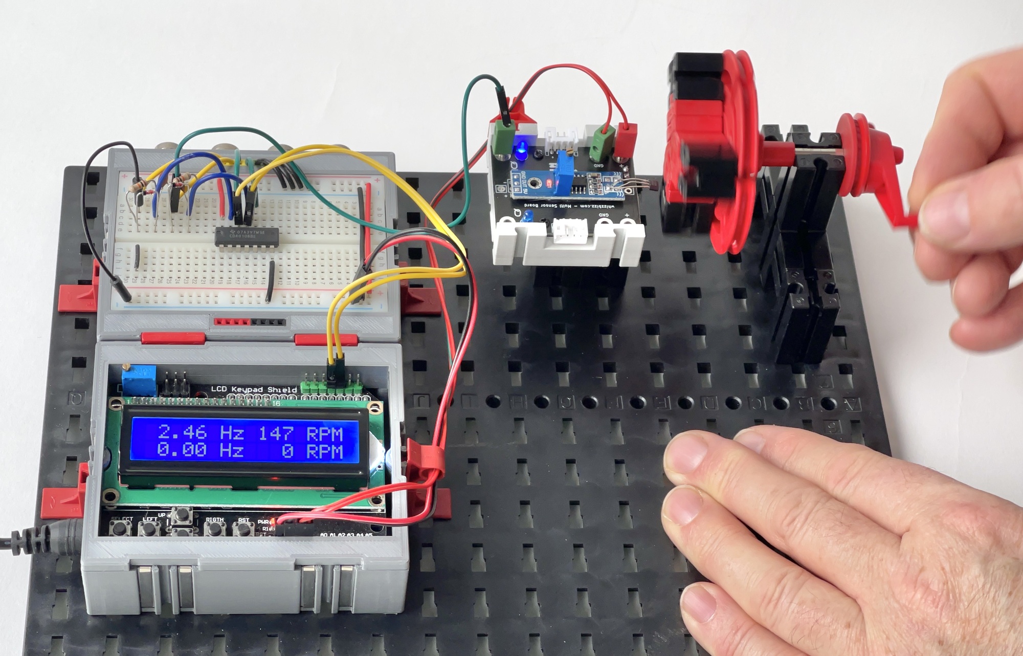
In the past, I used the IR obstacle sensors to measure rotational speed by building the double tachometer myself. Pictured is a possible tachometer with the Hall-Effect sensor in the adaptor module. A movement of the magnet along the sensor triggers a hardware interrupt that allows the rotation speed to be determined. The same principle is used when the pulse signal of the fischertechnik encoder motor (no.153422) is connected to a counter input of e.g. a TXT controller. Although such an external assembly takes more space, the measurement is (at least in theory) more precise. After all: by measuring closer to the actual end point of the movement, instead of at the origin in the motor, possible slippage or backlash of the (gear) transmission is automatically factored in.
The adaptor module is already proving its worth in various models. More information, photos and a link to a video can be found on the project page online. The 3D print files of some variants of the holder I designed for the adaptor print are available for download for anyone who wants to print them (or have them printed). There are still plenty of individual PCBs with the ready-assembled smd components in stock with me at this time.
For those who still want to improve the (PCB) design, the schematic, PCB design and 3D printing files are available on GitHub, but for those who want to get started right away I am of course happy to help with pre-assembled and tested adaptor modules. The four-pole JST cord (No. 337), the functional circuit board without (No. 338) and with (No. 339) JST connectors are available separately. In consultation, all sensors with holder are available in (almost) any color. See the online electronics catalog on this site for this.