
In a previous tinkering, the tinkering of a controller to be used at fischertechnik with an Arduino Pro Mini Atmega328P is described.
Once the hardware was assembled as a prototype, experimentation with programming the Zauberling could begin. For example, one of the starting points was to take over a lot of functionality from other fishertechnik modules.
Gradually, ideas arose to expand and/or improve this functionality. In this article I will go into more detail about this.
A successful magician must have a good magic wand, enchanting clothes and wonderful magic items. The 'hardware' must be in order. But to perform the true miracles, the inquisitiveness of spells and incantations is decisive. The spell is complete with the right magic formula, and it is precisely the combination of wand and spells that holds the true magic. Let's take a look at the great experimental magic book: the software of the Zauberling.

The nice thing about the Arduino Pro Mini Atmega328P is that it can be easily programmed from the Arduino IDE as soon as the bridge to the TTL interface of the small PCB has been made. In this way, the software can in principle always remain in development and can be easily expanded or adapted. After I had made some test programs for checking the control of the motor and servo outputs, I started to replicate the general functionality of the E-Tec and Electronics modules. Because the software of the Zauberling is so easy to adjust, I immediately adjusted the 'Basic program' on a few points. In part 3 of this article, this enhanced functionality is applied. In this section you will read which other tricks the Zauberling has already mastered.
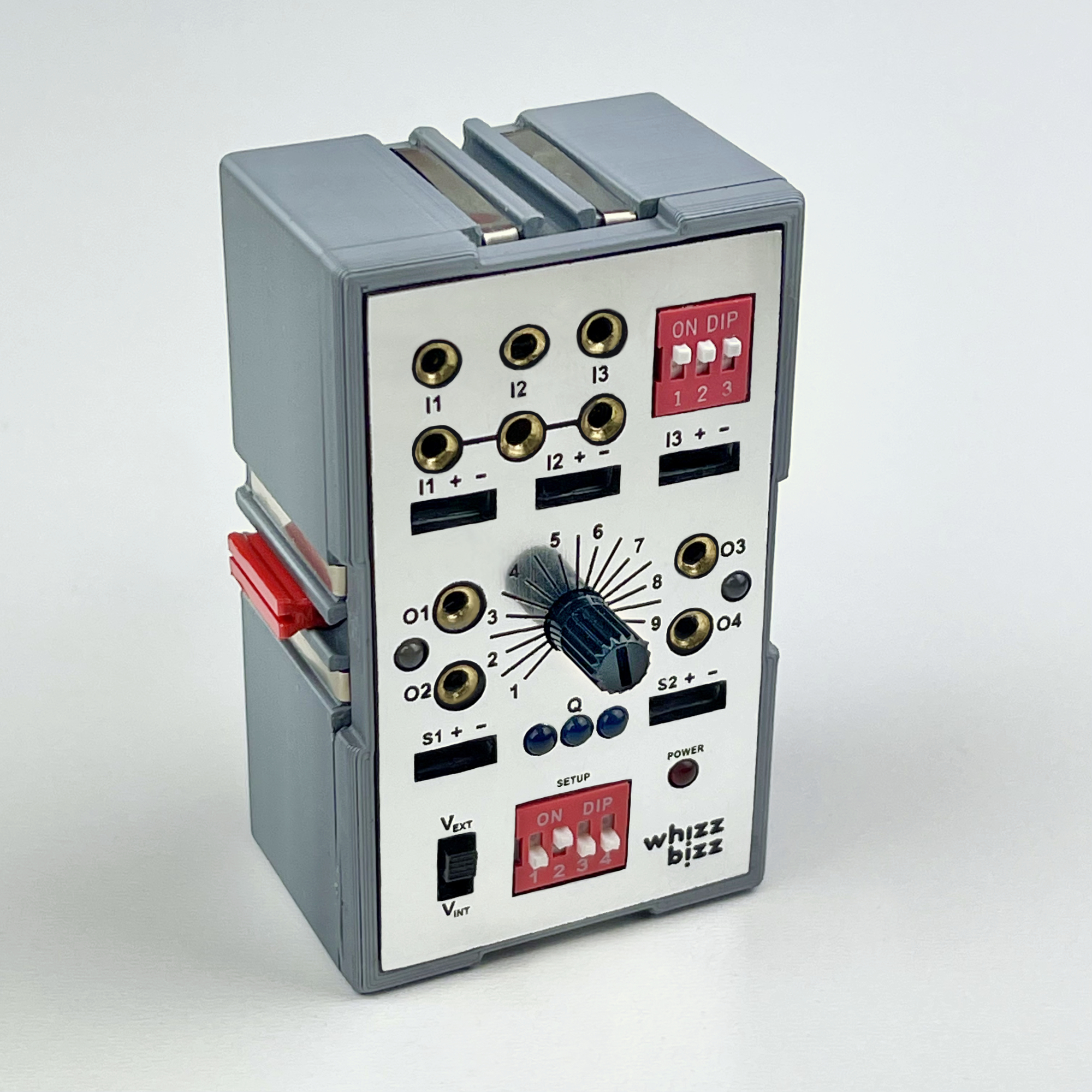
On the front of the Zauberling, it is possible to set which 'program' or control function is to be carried out using DIP slide switches. As with the E-Tec module, this makes it possible to quickly switch between various programs. This is especially useful for a programmable module such as the Zauberling during software development. For example, while an improved version of certain functionality is being worked on, an earlier stable version of this functionality can also simply be kept 'one setting away'.
The Zauberling is still a first prototype and the software is therefore still in development. The table below shows what has already been achieved, in various stages of perfection.
The 'Basic program' is known from the E-Tec module and requires three switches on the inputs. When switch 1 is pressed, the motor starts to rotate counterclockwise. When switch 2 is pressed, the motor starts to rotate clockwise. Pressing switch 3 stops the motor. A small change I made is that pressing switch 3 again will cause the motor to resume the last direction of rotation after the stop.
| Prog | DIP1 | DIP2 | DIP3 | DIP4 | I1 Logic | I2 Logic | I3 Logic | Function | Potentiometer |
|---|---|---|---|---|---|---|---|---|---|
| 0 | - | - | - | - | Negative | Negative | Negative | Basic Program with gradual speed curve | Time 0~2500ms |
| 1 | - | - | - | ON | Positive | Positive | Positive | Basic Program with gradual speed curve | Time 0~2500ms |
| 2 | - | - | ON | - | Auto | Auto | Auto | AND/NAND−Gate | Sensor Treshold |
| 3 | - | - | ON | ON | Auto | Auto | Auto | OR/NOR−Gate | Sensor Treshold |
| 4 | - | ON | - | - | Auto | Auto | Auto | XOR/XNOR−Gate | Sensor Treshold |
| 5 | - | ON | - | ON | Auto | Auto | Auto | SR-Flip Flop - SET=IN1, CLK=IN2, RESET=IN3 (R is dominant) | Sensor Treshold |
| 6 | - | ON | ON | - | Auto | Auto | Auto | JK-Flip Flop - J=IN1, CLK=IN2, K=IN3 | Sensor Treshold |
| 7 | - | ON | ON | ON | Auto | Auto | Auto | D-Flip Flop with Reset | Sensor Treshold |
| 8 | ON | - | - | - | Auto | Auto | Auto | Monoflop with Reset (set time with Potentiometer) | Puse Time 10~2500ms |
| 9 | ON | - | - | ON | Auto | Auto | Auto | Blinker (speed configurable) | Frequency |
| 10 | ON | - | ON | - | Auto | Auto | Auto | Flasher (speed configurable) | Frequency |
| 11 | ON | - | ON | ON | - | - | - | Future projects :-) | - |
| 12 | ON | ON | - | - | - | - | - | Future projects :-) | - |
| 13 | ON | ON | - | ON | - | - | - | Future projects :-) | - |
| 14 | ON | ON | ON | - | - | - | - | Demo: Motor directions/speed | - |
| 15 | ON | ON | ON | ON | - | - | - | Demo: Servo movements | - |
| bit3 | bit2 | bit1 | bit0 |
It is usually important to know whether a switch or sensor at the input is open or closed in rest position and thus how to interpret the detecting behavior. For a program such as the 'Basic program' in the E-Tec module, this makes sense, for example, because one of the switches may already be pressed when the module is switched on and the motor must therefore immediately start running in the right direction to restart it. free to play.
On the other hand, it is nice to be able to use both voltage drops and voltage rises as logic detection levels at the inputs. Examples of sensors that cause a voltage rise when they have to report are, for example, the photo-transistors or a switch that is grounded in the rest position. However, some sensors react the other way around, such as, for example, the output signal of an active IR obstacle sensor at rest is 5 volts and this drops to zero volts when an obstacle is detected. You could call this 'negative logic'.
For this reason, I had set myself the challenge of keeping the processing of the Zauberling's input signals as uniform as possible. The module can be used more flexibly if (almost) all types of sensors and logic at the inputs can be used interchangeably. After all, usually only signaling the deviating output position is sufficient as a switching pulse.
It is of course possible to save the measured input values as reference values when switching on (or after a reset) of the Zauberling. A threshold value can be set with the potentiometer on the front. An input becomes 'active' as soon as the corresponding reference value is exceeded by more than the threshold value. It does not matter whether the value deviates upwards or downwards from the reference value. The set threshold value also serves as a measure of the hysteresis for sensors that only gradually return to their initial value after detection and thereby pass through the area around the threshold value. This prevents the input from 'flapping' when the sensor's output value moves in the area around the detection threshold. The detection behavior of a sensor slowly returning to the reference value is tempered in this way.
The software will remain in development for a while. The (simplified) code snippet on the right shows the measurement of the baseline values and how the threshold and hysteresis are handled.
This trick makes it possible to use the Zauberling's inputs with a wide variety of sensors. Active sensors such as the IR obstacle sensor, the PIR motion sensor or a hall effect sensor can also be used. The only condition is that the reference value can be measured at the start with an 'unactivated' sensor. Since most control systems mainly use the sensors as detectors, this requirement is often met in practice.
But of course there can be specific exceptions. For some controls (such as the 'Basic program', for example, it is better if the sensor type and behavior can be chosen in a fixed way. The software is set up in such a way that this choice must also be made explicitly for the 'Basic program'. Two variants are included so that it can be used both with conventional sensors with positive logic (such as the familiar light box with photo-transistor) and with sensors with negative logic.
void setup() {
  …
  in1Default = analogRead(IN1);
  in2Default = analogRead(IN2);
  in3Default = analogRead(IN3);
  …
  …
}

void loop() {
  …
  …
  potValue = analogRead(POTMETER);
  sensorTreshold = map(potValue, MINREG, MAXREG, 1, TRESHOLD_MAX);
  …
  …
  // Read inputs ,take hysteresis into account
  in1Value = analogRead(IN1);
  if (abs(in1Value-in1Default) > sensorTreshold) {
    in1ValueTrigger = in1Value;
    in1Active = true;
  } else {
    if (abs(in1Value-in1ValueTrigger) > sensorTreshold/2) { // Hysteresis...
      in1Active = false;
      in1TriggerUsed = false;
    }
  }
  in2Value = analogRead(IN2);
  if (abs(in2Value-in2Default) > sensorTreshold) {
    in2ValueTrigger = in2Value;
    in2Active = true;
  } else {
    if (abs(in2Value-in2ValueTrigger) > sensorTreshold/2) { // Hysteresis...
      in2Active = false;
      in2TriggerUsed = false;
    }
  }
  in3Value = analogRead(IN3);
  if (abs(in3Value-in3Default) > sensorTreshold) {
    in3ValueTrigger = in3Value;
    in3Active = true;
  } else {
    if (abs(in3Value-in3ValueTrigger) > sensorTreshold/2) { // Hysteresis...
      in3Active = false;
      in3TriggerUsed = false;
    }
  }
  …
  …
}
In both variants of the 'Basic program' it is checked whether the sensors meet their characteristic at the start (so for example a low voltage at the relevant input is measured if the 'Basic program' is used in positive logic). Only one sensor/input may deviate from which it is assumed that it already reports at the start and does not start in the unactivated rest position. As soon as the input levels of the sensor change, the sensor is then re-initialized during the course of the program where the reference value is measured and stored.
If, when using the 'Basic program', more than one sensor deviates at the start, an error is given by flashing the three leds on the front simultaneously. In this case, the wiring should be checked. In most cases it is sufficient to plug the mechanical switch 3 (start/stop) from 'normally closed' to 'normally open' (or vice versa) to reset the module.
What can be done in software does not have to be done in hardware. When studying the circuit diagram in part 1, the observant electronics engineer would have noticed that no suppression capacitors have been included at the inputs. For each input, a semaphore inxTriggerUsed is reset in the software (see code fragment above) that can be set in the processing routine to signal that the triggering edge of the signal has been 'processed'. This ignores any false extra switching pulses or noise around the mechanical switching point of, for example, a switch.
One of the minor annoyances of the standard 'Basic Program' for me was that the engine does not start smoothly when switched on, or has a smooth ramp when switched off. And especially at the points where the direction of rotation changes abruptly, a gradual progression would be more pleasant to avoid wear on the engine and unnecessary forces on the model.
Instead of a hard polarity reversal as in the first graph, a gradual progression along the middle graph would be more desirable.
The Zauberling is now able to do this and the 'Basic Program' has been adjusted accordingly. However, the torque of the motor at low speeds and around standstill turns out to be so low in practice that the graph cannot be followed exactly. Therefore, the curve could be replaced by a straight line, as in the last graph, without any problems. This obviously made the software even easier.


In the (simplified and abstracted) code fragment on the right, the number of steps in which the speed and/or the direction of rotation must occur is first determined. This is done based on the value that can be set with the potentiometer on the front. If this is turned all the way to the left (to zero), the behavior is as known from the E-Tec module. As the potentiometer is turned more to the right, the speed and direction changes become more gradual. The time for this is adjustable from 0 to 2.5 seconds. In the video I made you can see how buttery the engine turns off and starts up again.
Although this talent would not be out of place in a magician, unfortunately the Zauberling has not yet been able to predict the future. So keep in mind that this motor shutdown takes place after the sensor detection. The moving construction must of course facilitate this and not get stuck or collide. In practice, however, this can easily be taken into account when choosing the position of the sensors. An additional advantage could even be that this property can be used to adjust the maximum deflection of a moving carriage without moving the sensors.
The Zauberling cannot yet handle stepper motors, so the distance traveled is now only determined on the basis of the set time. As a result, it will vary at different transmissions of the engine. Should a next incarnation of the Zauberling receive more inputs, it would be possible to use them for the feedback of an encoder motor. For now, though, I didn't think all that was necessary.
void setMotorSpeed(bool rotateDir, int motorSpeed, bool smooth) {
  // rotateDir = true means O1/O2 CW rotation
  // rotateDir = false is O1/O2 CCW, output O3/O4 is reversed
  // motorSpeed is a value between 0 and 512
  // smooth = potmeter setting is value of gracefully descend and ascend
  int tempSpeed;
  int speedStep;

  if (rotateDir!=currentMotorDir || motorSpeed!=currentMotorSpeed) {
    int smoothDelay = timeDelay/25;
    if (currentMotorDir == rotateDir) { // No directional changes...
      speedStep = (motorSpeed-currentMotorSpeed)/SPEED_STEPS;
      tempSpeed = currentMotorSpeed;
      do {
        tempSpeed += speedStep;
        if (abs(motorSpeed-tempSpeed) <= abs(speedStep)) tempSpeed = motorSpeed; // Last step...
        delay(smoothDelay);
        if (rotateDir) {
          Out1.drive(tempSpeed);
          Out2.drive(-tempSpeed);
        } else {
          Out1.drive(-tempSpeed);
          Out2.drive(tempSpeed);
        }
      } while (abs(motorSpeed-tempSpeed) > abs(speedStep));
    } else { // Towards and through zero...
      for (tempSpeed=currentMotorSpeed; tempSpeed>0; tempSpeed-=(currentMotorSpeed/SPEED_STEPS)) {
        // Slow down to zero...
        delay(smoothDelay);
        if (currentMotorDir) {
          Out1.drive(tempSpeed);
          Out2.drive(-tempSpeed);
        } else {
          Out1.drive(-tempSpeed);
          Out2.drive(tempSpeed);
        }
      }
      speedStep = motorSpeed/SPEED_STEPS; // Always positive...
      for (tempSpeed=0; tempSpeed<=motorSpeed; tempSpeed += (motorSpeed/SPEED_STEPS)) {
        // Build up to motorSpeed again...
        if (abs(motorSpeed-tempSpeed) <= speedStep) tempSpeed = motorSpeed; // Last step...
        delay(smoothDelay);
        if (rotateDir) {
          Out1.drive(tempSpeed);
          Out2.drive(-tempSpeed);
        } else {
          Out1.drive(-tempSpeed);
          Out2.drive(tempSpeed);
        }
      }
    }
    currentMotorDir = rotateDir;
    currentMotorSpeed = motorSpeed;
  }
}
The software for the Zauberling will probably be further expanded and refined in the near future and can be downloaded from GitHub. Please do not hesitate to email or contact me on the fischertechnik forum if you have any suggestions, comments, questions or ideas for future functionality for the Zauberling. After all, for a true wizard, the seemingly impossible is the ultimate challenge... 😄