
Sensors and sensors are the eyes and ears of a process control. In the past, light steel breakers and push buttons were mainly used, but nowadays there are numerous handy 'breakout boards' available with contactless sensors.
Because I had arranged the 5 volt power supply in an earlier project for my experiments with (fischertechnik) electronics modules, I thought it was a good time to play with a contactless touch switch.
These small contactless switches prove to be an excellent replacement for mechanical switches and push buttons.
In digital electronics, a synchronous circuit is a digital circuit or component whose changes in state are synchronized by a clock signal. The Flipflop or Monoflop are a good example of this. The required 'clock pulse' is nothing more than a signal with a very steep potential transition. If a sensor, sensor or push button in a model or control is to be used as such a control signal, it is important that this transition, the switching moment, is sufficiently 'suppressed'.
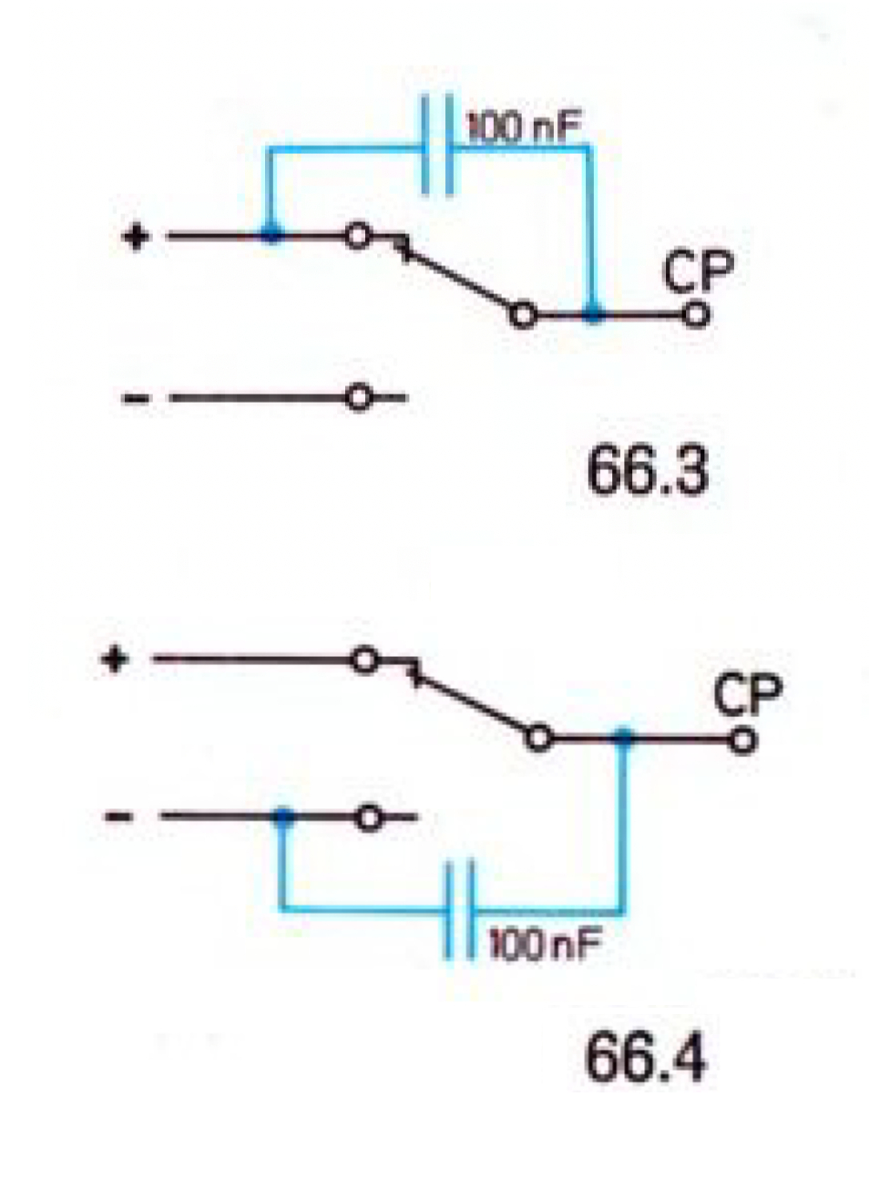
This phenomenon has already been explained in the fischertechnik (electronics) hobby books. The noise from the contacts at the switching moment can easily be incorrectly interpreted as a series of clock pulses in rapid succession and therefore produce unpredictable results. To use a push button or switch as a usable clock pulse for the CP input of the Flipflop, it is recommended to suppress interference with a 100 nF capacitor. The capacitor removes interference from the signal around the switching moment, but the level transition does not become steeper. However, the signal jump when switching between the plus and minus poles in Figure 1 is so large that a push button can be sufficiently suppressed in this way. When using a sensor with a slower progression around the switching moment (such as a light-sensitive resistor or a temperature sensor), connecting a differential amplifier or Schmitt trigger beforehand offers a solution.
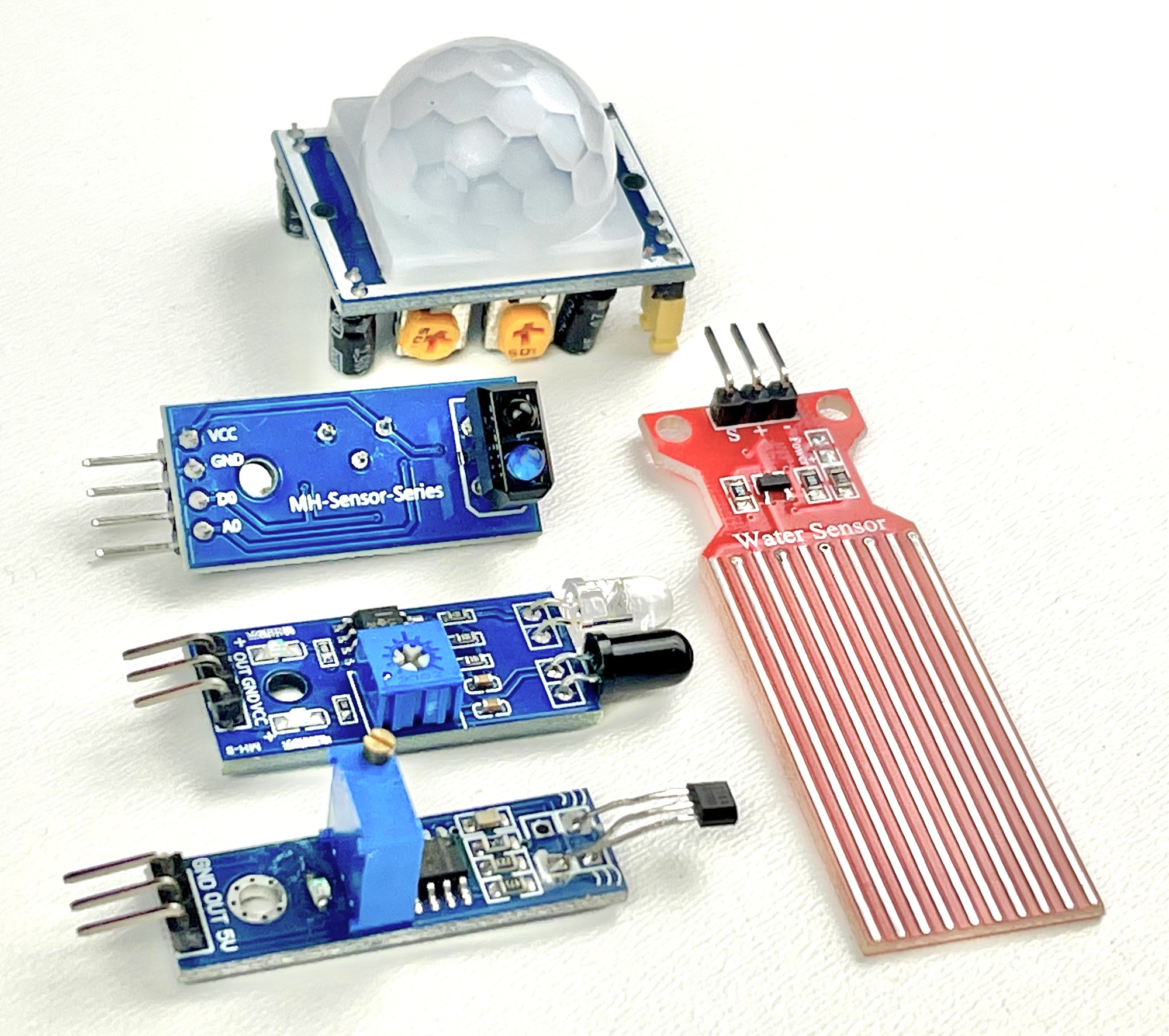
Since experimenting with microcontrollers such as the Raspberry and Arduino has taken off, the range of affordable interesting sensors and actuators has increased enormously. There are so-called breakout boards with sensors for obstacle detection, temperature, movement, magnetism, water, vibration, light, etc. Many of these boards require a power supply of 5 volts.
A nice development is that most modern sensor boards themselves are already equipped with a differential amplifier or Schmitt trigger, so that the output signal of these boards can be used directly in synchronous circuits without interference. In software (for example when using an Arduino), no waiting time after the signal change is required when detecting a stable signal level, as is usual when reading a normal push button. Even when connecting to hardware, such as in this test setup with the classic fischertechnik electronics modules ('Silberlingen'), it is therefore not necessary to 'suppress' any switching noise.
The modules in the image above, with sensors for obstacles, humidity, movement or magnetism, can therefore be used directly in digital circuits without 'interference'. Nowadays, Hall and Obstacle sensors are increasingly used as a 'contactless' modern replacement for traditional push buttons. An alternative to human-operated switches or push buttons could be a touch switch. Information about different types of sensors and their detection methods can be found online elsewhere.
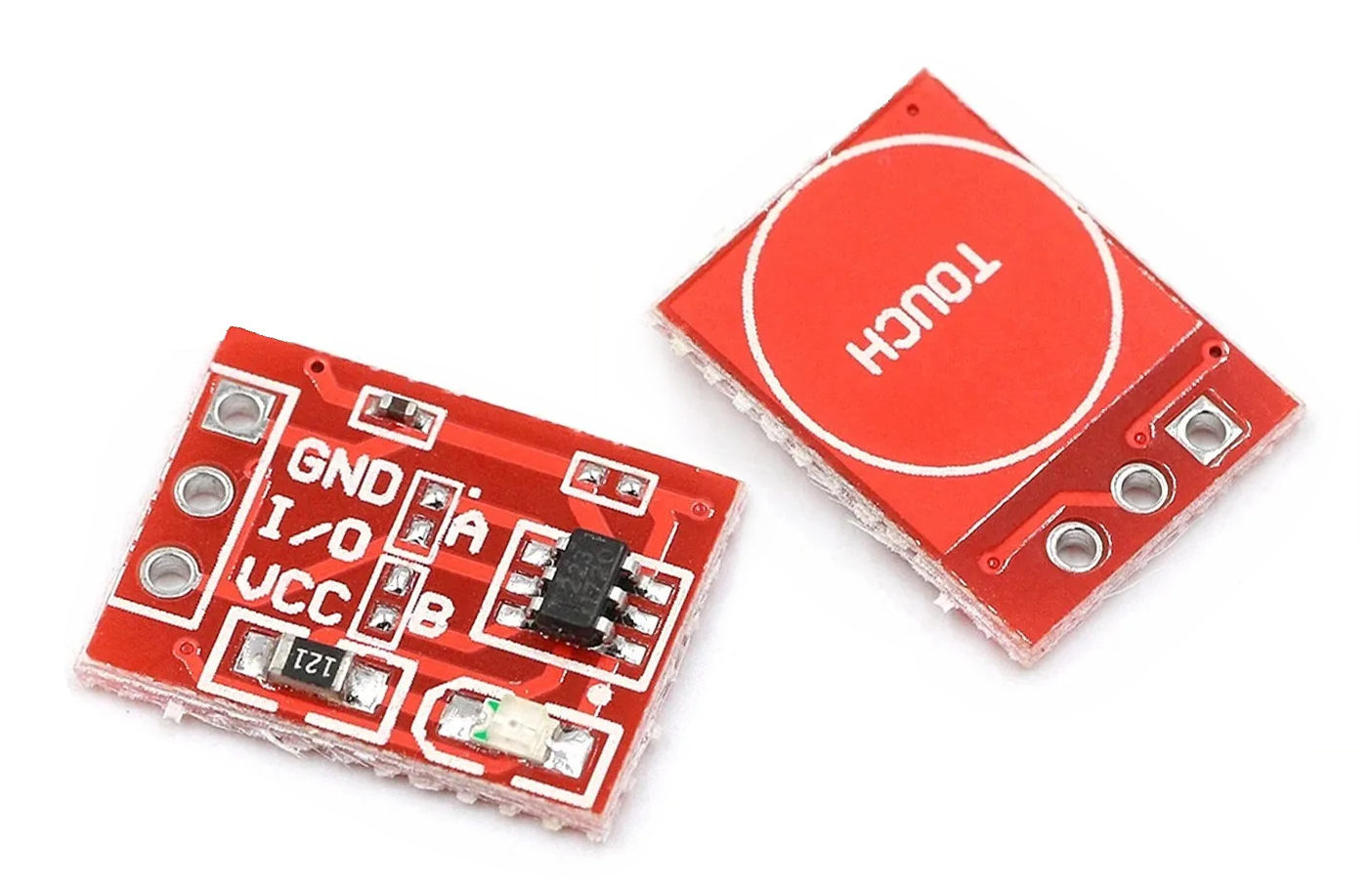
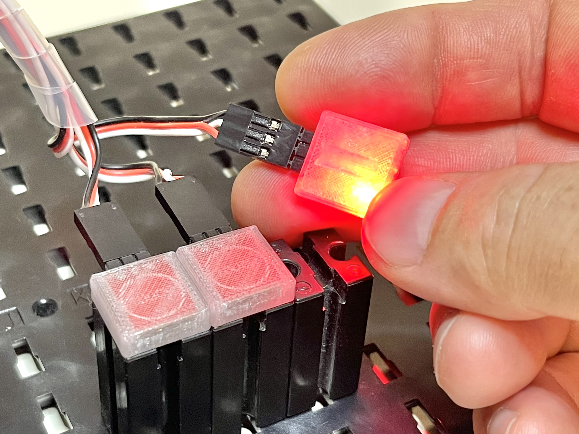
Nowadays these small (11x14 mm) sensors can be purchased for very little money. After soldering a three-pin Dupont connector and possibly making a three-pin Dupont connection cable yourself, this contactless switch is ready for use. When you place a finger on the sensor surface (marked 'TOUCH'), the I/O output signal becomes equal to the supply voltage, which is between 2.5 and 5.5 Volts.
The functionality of the touch switch can still be modified. The sensitivity can be expanded even further by installing an (SMD) capacitor. For the sensors I tested, this was absolutely not necessary, when a light touch (or even a close approach) to the sensor, the LED on the bottom of the small circuit board immediately lit up, so that the sensor itself immediately provides useful feedback about the detection. An additional advantage is that this visual feedback does not have to be provided by the underlying control in which the sensor is used.
In the past I had experimented with the RCWL-0516 radar and 'Human Body' sensor, but these turned out to be actually unusable as a touch switch due to their much too great sensitivity. The 'TTP223 Touch Switch Sensor' certainly does not have this problem and this means that several of these touch buttons close to each other can still be operated with the right precision. That is why it will probably take little effort to create a compact control panel, keyboard or even musical keyboard that can easily 'arrange' a lot on a small surface.
However, the small PCB offers even more possibilities. Solder jumper A (see detail photo of the sensor) can be closed to switch the signal logic from positive to negative. By closing this jumper, the signal output is 5 volts after switching on and without touch, but drops to 0 volts when a touch is detected.
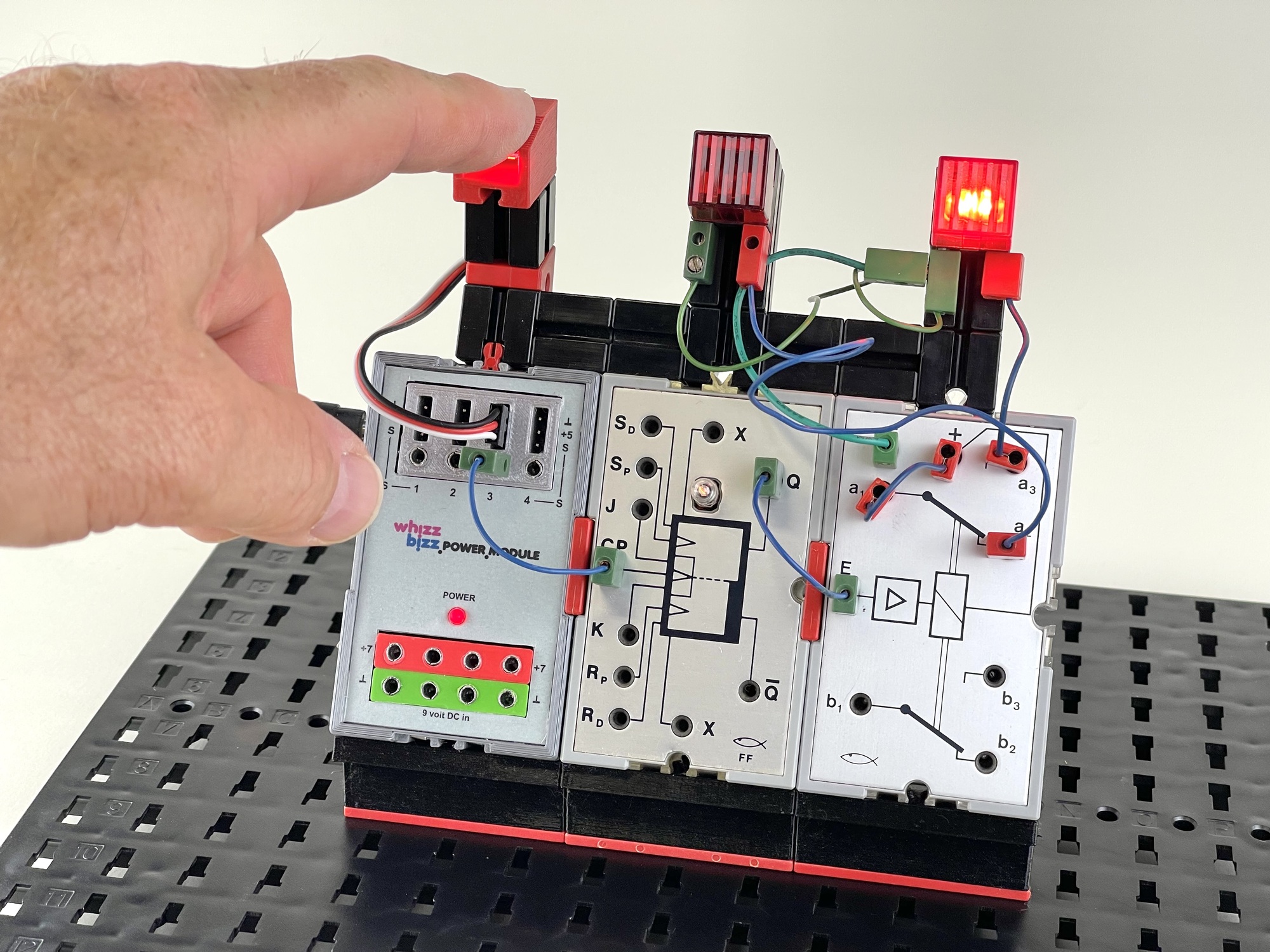
This mode makes the signal output even more suitable, for example, when using the traditional fischer technology 'Silberlingen' (electronics modules of which the Flipflop and a relay module are used in the example application below), which work with so-called 'negative logic'.
Solder jumper B is even more interesting. When closing this jumper, the signal output behaves like a T-Flipflop. So something can be switched on with a touch, and switched off again with a second touch. This quickly saves a variable and test condition in the software if the sensor is used with a micro, TX or TXT controller, or a complete Flipflop (module).
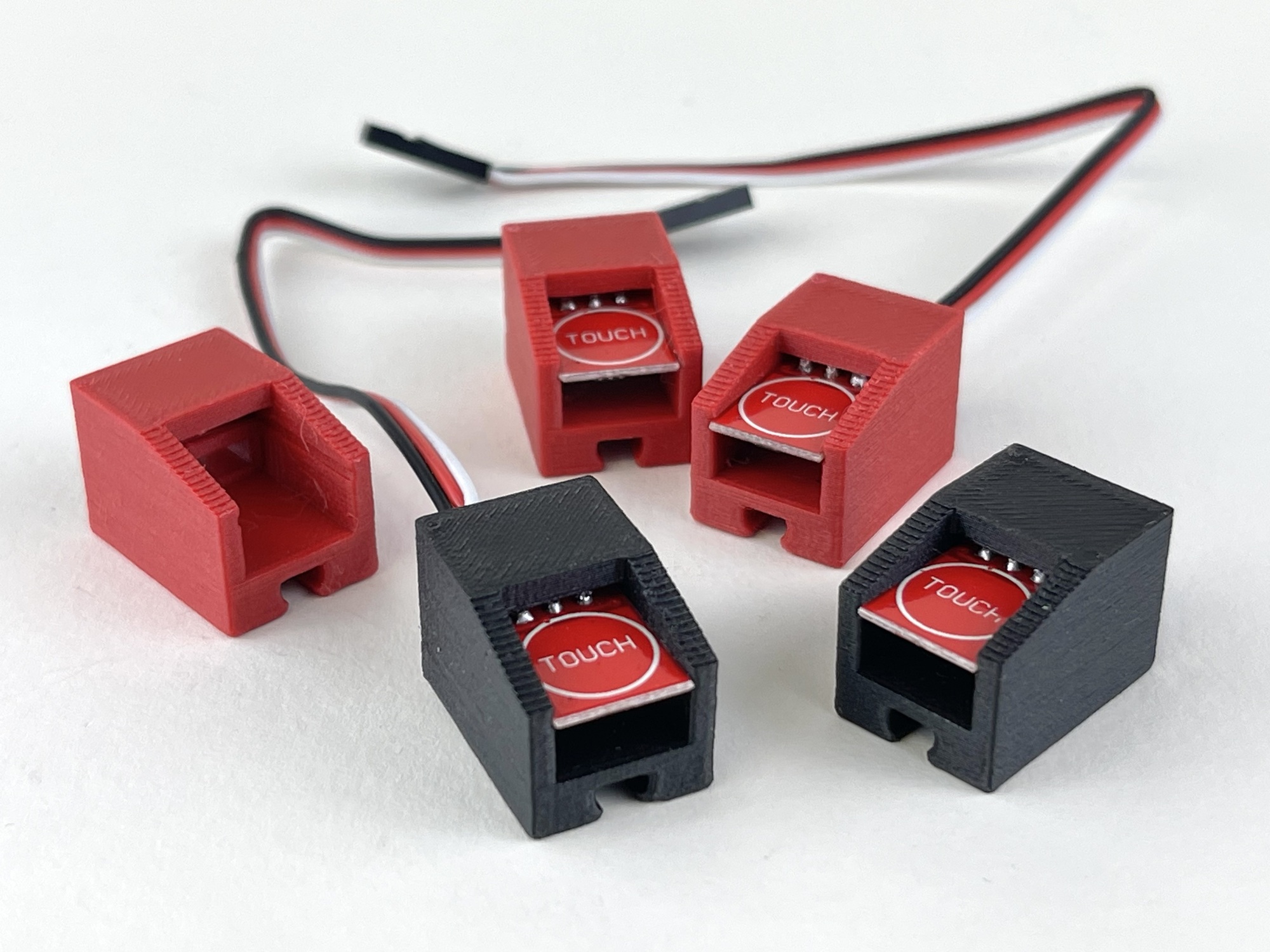
To make it easy to use the touch switches in fischertechnik projects, I designed and printed a few variants of small building blocks and building plates for them. The thin (5mm) building block printed with transparent material works as a diffuser for the light from the LED at the bottom of the board. I also made a thicker building block variant where the sensor surface remains visible. The light of the (red) LED on the bottom of the sensor is visible in the opening under the circuit board when it is activated. For these sensor building blocks I chose the color red for normal touch behavior and black for the sensors that switch alternately.
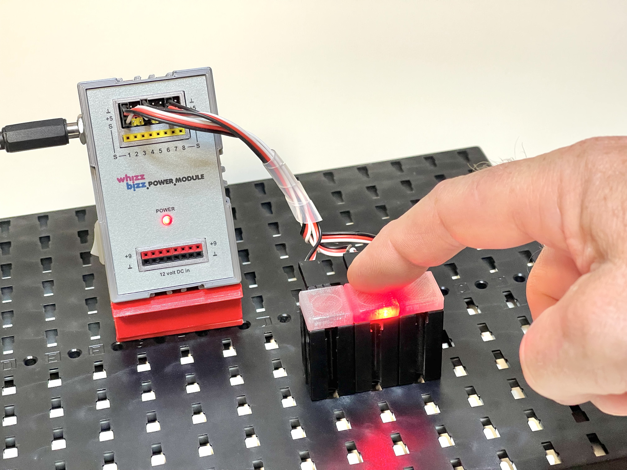
To illustrate, I built the circuit in which a touch switch alternately switches between two lamps via a Flipflop (see photo). The attentive reader will recognize the power supply module with connection options for sensors with three-pin Dupont plugs, which is described on another project page of this site.
It is technically most robust when the positive pole of these sensor boards is designed as the middle connection pin. However, with the sensors in the photo above, this is only the case with the humidity sensor. The TTP223 also has a different order for the three connection pins. This is certainly something to pay attention to when making the three-pole Dupont cables, or when soldering the connecting wires. The good news is that my TTP223 did not immediately die when I accidentally connected it incorrectly. And if this does happen, it will probably not be an insurmountable problem with a purchase price of approximately 10 euro cents per piece.