
Coincidentally, I came across references to the intriguing figures I used to draw as a child with the "Spirograph" in quick succession. Soon I was dizzy with the different terms. Because what exactly is a 'cycloid', 'hypocycloid', 'epicycloid' or 'trochoid'? And would it be possible to project these wondrous figures, both mechanically and electronically, with a small semiconductor laser?
As an experiment, I doubled the six-speed gearbox. After seeing the mechanical solution in action, I built the 'projector' with a significantly smaller footprint by electronically controlling the rotating mirrors.
A cycloid is a mathematical figure. It is the path taken by a point on a circle rolling over or inside another figure (such as another circle). Visually very striking are the hypocycloids, where a (gear) wheel rotates inside another (gear) wheel. A dot on the circumference of the inner gear describes, when we turn this gear, a curve that we call a hypocycloid. If we do not place the dot on the edge, but more towards the rotational point, we call this curve a trochoid. Hypo- is Greek for "under" and epi- is Greek for "on". If we put a small cog inside a larger one, we draw hypotrochoids, if we make a small cog go around the outside of the larger one, then epitrochoids appear. Without realizing it, we were already drawing real trochoids as children with the old Spirograph drawing set!
Read more about the mathematical background of these intriguing figures on the Wikipedia page on cycloids. That's also where the illuminating animation on the right comes from.
In practical terms, cycloids are created by 'modulating' (multiplying) a circular curve (such as the path described by the dot on the inner wheel) of a certain diameter by a second circular curve of a different diameter (such as the outer wheel over which, or within which , the other wheel is spinning).
The ratio between the radius of the outer and inner (cog)wheel determines the shape of the cycloid. The explanation with small animations on the Wiki page about hypotrochoids clarifies the matter and also makes clear that there are several specific variants within the cycloid family. In addition to the usual pointed cycloids, there are both truncated and elongated epicycloids (outside), pericycloids (following the perimeter), and hypocycloids (inside), which are called epitrochoids, peritrochoids, and hypotrochoids, respectively. Are you dizzy already? 🤓
When a laser beam falls on a second 'wobbling' mirror, the final light beam describes a cycloidal curve. The first mirror would then represent the contribution to the resulting curve from one gear. This (circular) light curve is then 'modulated' by the second mirror, similar to the influence of the other gear. With such curves, the laser point of light quickly describes a path that does not completely fall within the enveloping, largest, circle. Such cycloids could be called hypotrochoids. The figures show great similarities with the mathematical Rose figures.
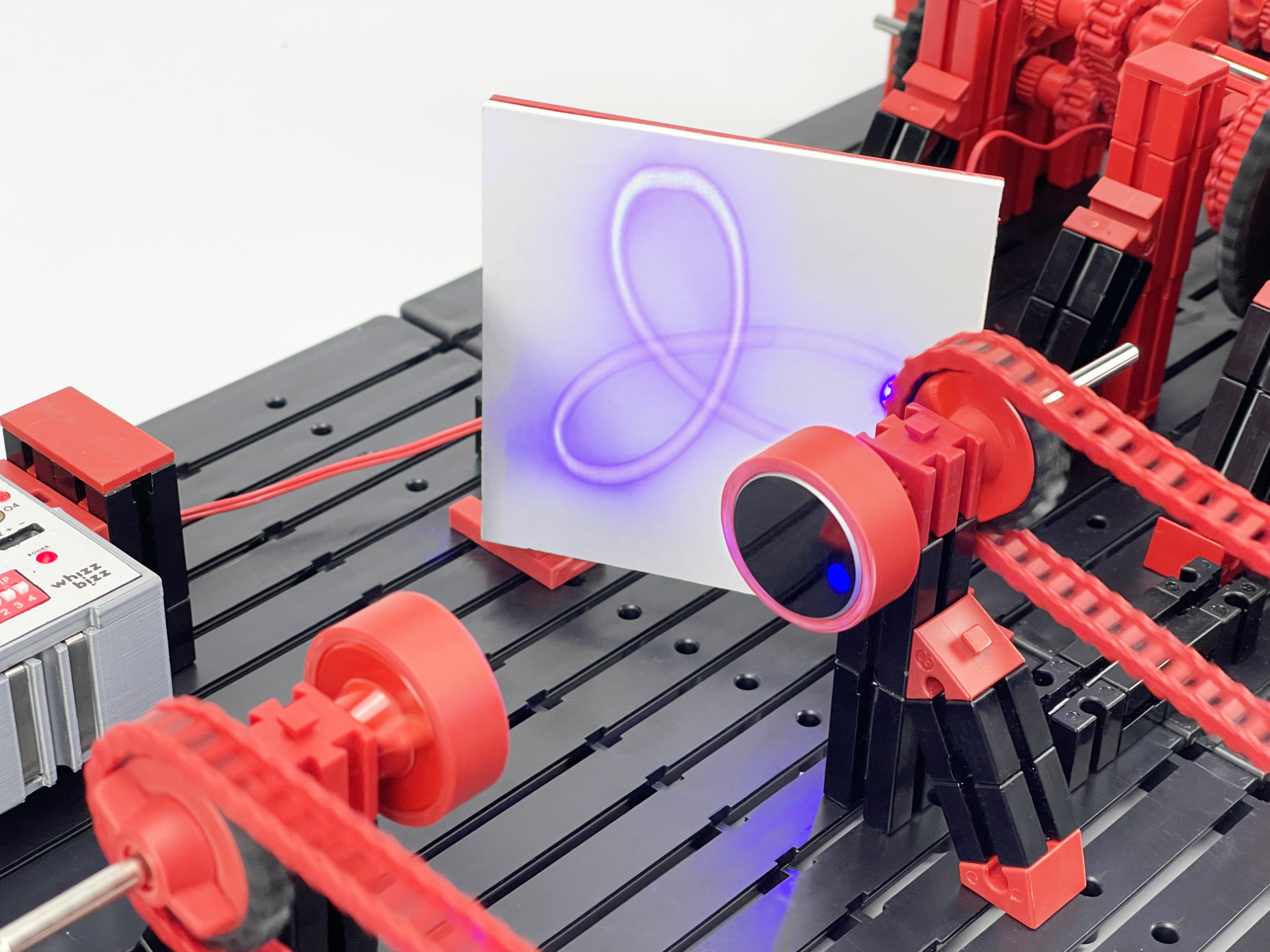
The final figure formed depends, as with the gear ratios of the Spirograph, on the relationship between the two rotational speeds of the mirrors. The matrix above gives an impression of the shapes that arise at different ratios n/d. Note that if both mirrors have exactly the same rotational speed, the result is a simple (relatively small) circle. The same happens if one of the mirrors simply does not rotate at all. The Rose figures shown in the image lack the gap in the center of the various trochoids that can be drawn with the Spirograph. But with some imagination it can be seen that the flower-like figures from the first line change with more complex proportions into the figures we know from the Spirograph from our youth.
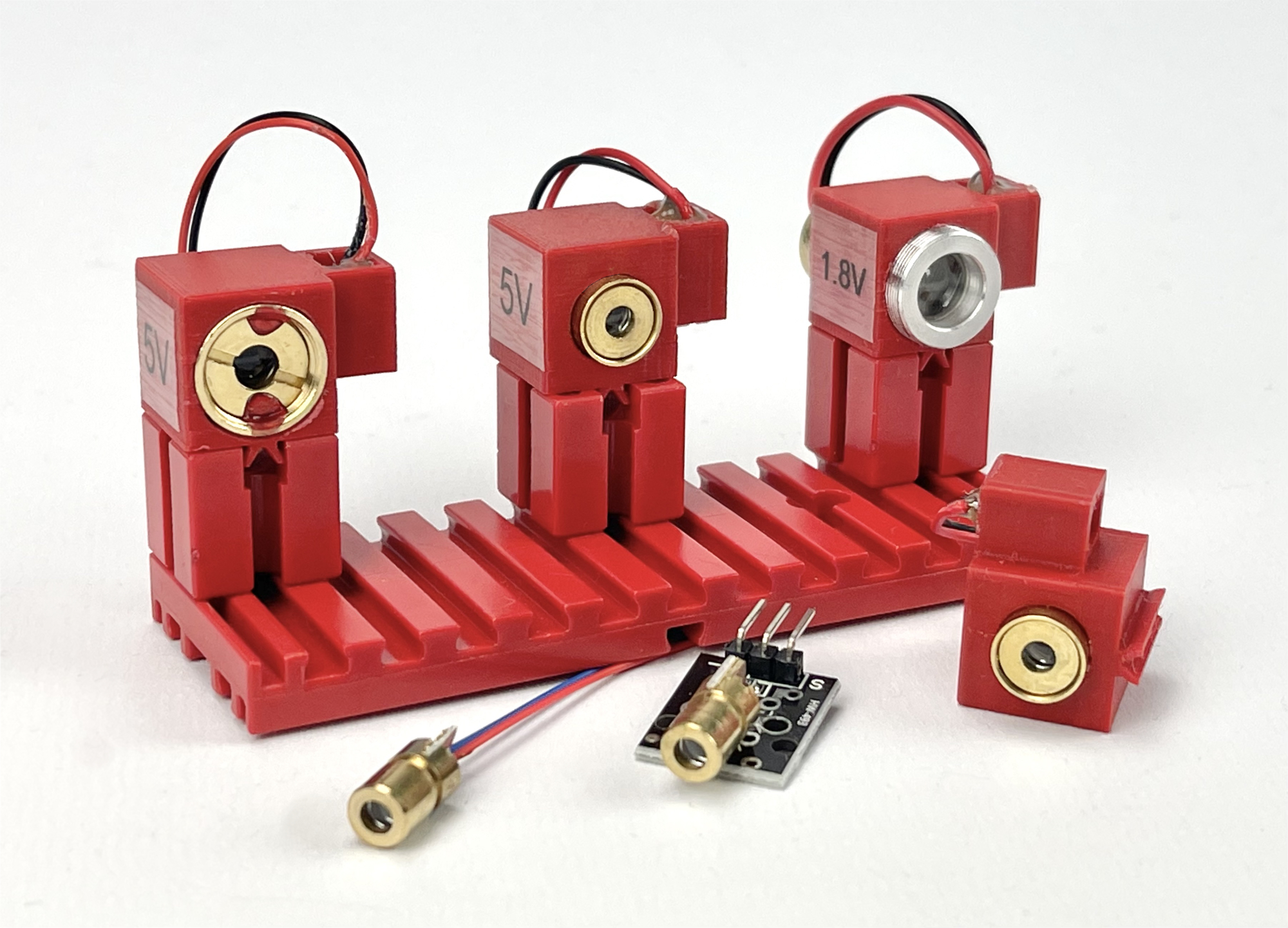
I seemed to have already collected a number of different semiconductor lasers for various experiments and projects. Various red (650nm), a blue (450nm) and a green (532nm) laser. None of these are really highly focused. The laser dot quickly has a diameter of a few millimeters. In addition, the lasers with low power (<50 mW) actually have too little light output for projection. The projected figures are hardly visible in daylight. In the end I therefore simply used the laser with the most power: a 100mW blue laser that has a considerably higher power and therefore produces more recognizable projected figures.
Although these lasers are relatively weak, they can still cause eye damage if you look directly at them. So, as with all lasers, some caution is advised. A diameter of 30 mm turned out to be sufficient for the mirrors. By placing the mirrors slightly closer together, even a diameter of 20 mm turned out to be enough. It is only important that the circular curve formed by the first mirror falls entirely on the second mirror. In principle, small mirrors from an inspection telescope, dentist's or makeup set can also be used. For my very first experiments I simply cut small round mirrors out of reflective PVC sheet which I glued directly onto a fischertechnik motor axle at a slight angle using a hot glue gun.
If you really want to do it right, buy a pair of optical surface mirrors online. The reflective layer here is on the surface of the mirror and the laser beam does not first have to pass through the transparent glass (the surface of which will also reflect part of the light). As a result, "ghost reflections" are avoided and the final projected image is not unnecessarily "clouded".
In the end I designed a few different holders for the mirrors. The platform with the mirror makes an angle of 4 degrees with the hub or the platform so that the rotating mirror starts to 'wobble' by itself.
In order to mechanically give the two rotating mirrors different rotational speeds from one common motor, a mechanical gearbox would ideally have to be built with two output shafts, the rotational speeds of which can be individually controlled.
To be able to make as many different hypotrochoids as possible, a gearbox with as many consecutive gears as possible would be ideal. The best thing would be if it were possible to make a mechanical gearbox where, for example, the ratios 1:1, 1:2, 1:3, 1:4, 1:5 and 1:6 could be made. If this gearbox, driven by a single motor, is eventually implemented in duplicate, it is possible to project a whole matrix of 6 by 6 (so also, for example, the ratios 3:4 and 5:4, etc.) from the Rose figure matrix above.
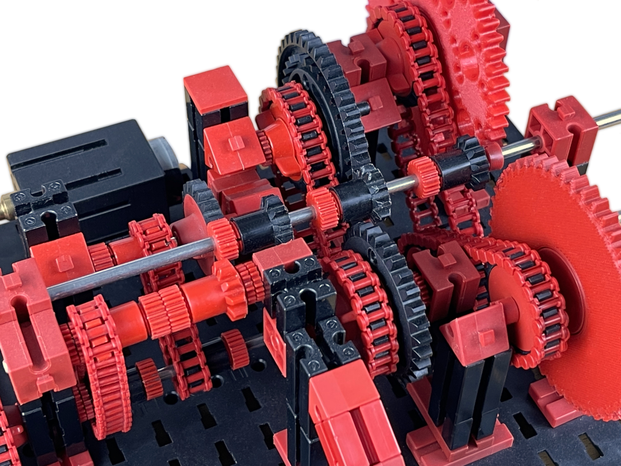
It seemed easy to me to use my favorite construction material fischertechnik for the construction. The gears with ten (Z10), twenty (Z20), thirty (Z30) and forty (Z40) teeth would then be immediately available. However, the Z50 and Z60 gears are not part of the standard fischertechnik range, but the 3D printer offered a solution for that.
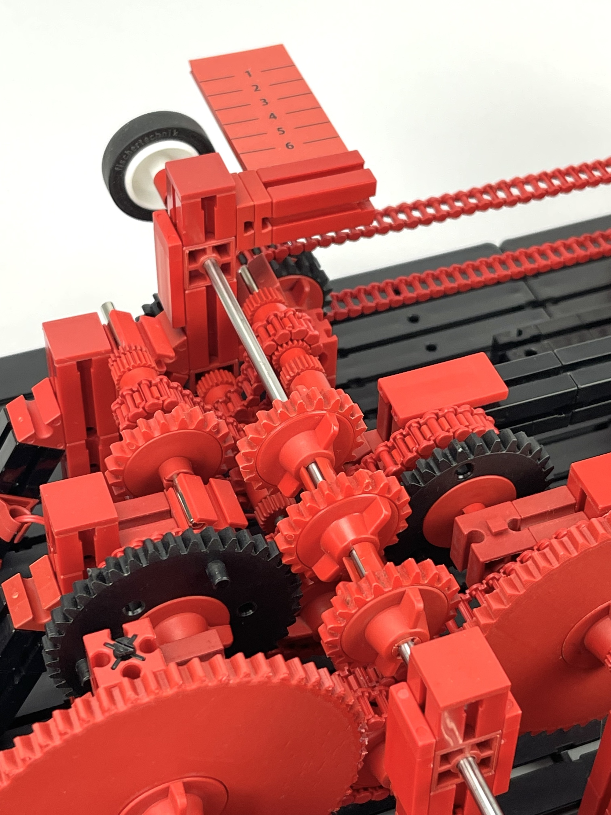
I equipped the first prototype of the gearbox with three Z10 gears on the sliding output shaft. The spacing of the series of six driving sprockets has been chosen such that each Z10 sprocket on the central shaft is driven by only two drive sprockets in the entire stroke of (6 x 7½ =) 45 mm. The schematic diagram is shown in the figure below. Each dotted line is a distance of half a fischertechnik unit of 15 mm and thus represents a distance of 7½ mm.
Ideally, in order to easily compare the influence of the possible rotation speed ratios on the different projected figures, the gear box could be switched while it is rotating. It became clear that the use of gears Z10 on the central shaft was not ideal. This sprocket actually has too small a circumference for the modulo 1.5 toothing. Because the diameter of the wheel is too small, the teeth are 'undercut' too far and do not form the ideal dimensions. This makes shifting more difficult and creates more play. In a follow-up model, I therefore replaced these shifting gears on the main shaft with three Z20 gears. However, the adjustable ratios per side of the gearbox became ½, 1, 1½, 2, 2½ and 3. Although the output rotation speed is thus halved, the ratios are retained, the gearbox shifts more easily and runs considerably more silently.
I made a video of the construction search for the gearbox with six ascending gears in which you can see (and hear!) it in action. First the sliding motor shaft with three gears with only 10 teeth is visible, later the 'improved' model with Z20 gears on the central shaft.
However, to make the projections it was of course necessary that two mirrors could be driven. For the sequel, the gearbox therefore had to be built again. This second copy is built in mirror image and the output shaft immediately has the desired opposite direction of rotation.
Because I had the opportunity, I designed and printed some custom parts for the drive part of the gearbox. The gears Z50 and Z60 have already been mentioned above. To reduce the rotational movement of the sliding main shaft, I designed a thickened model Z20. For other applications, this 'Z20 barrel' can be extended modularly with 10 mm intermediate discs. The STL files to print these parts yourself (or have them printed) can be found here.
Because I was busy anyway, I replaced the initially improvised mounting solutions (happy glue gun!) for the lasers and the 'wobbling platforms' for the mirrors with self-designed, 3D printed solutions.
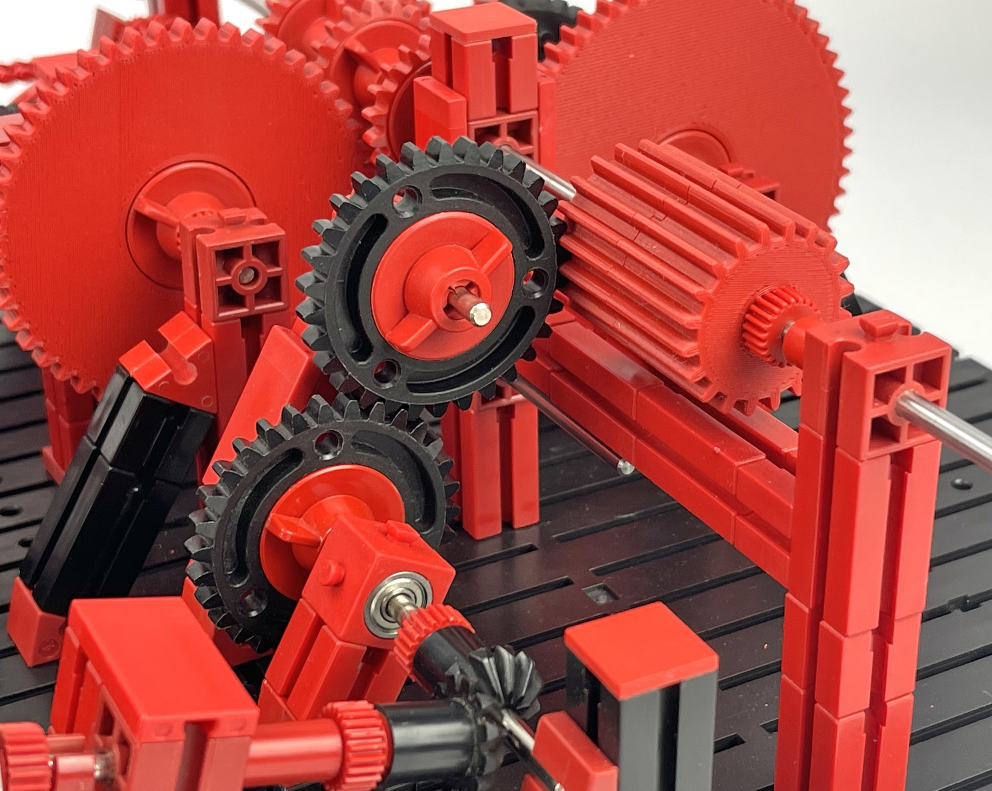
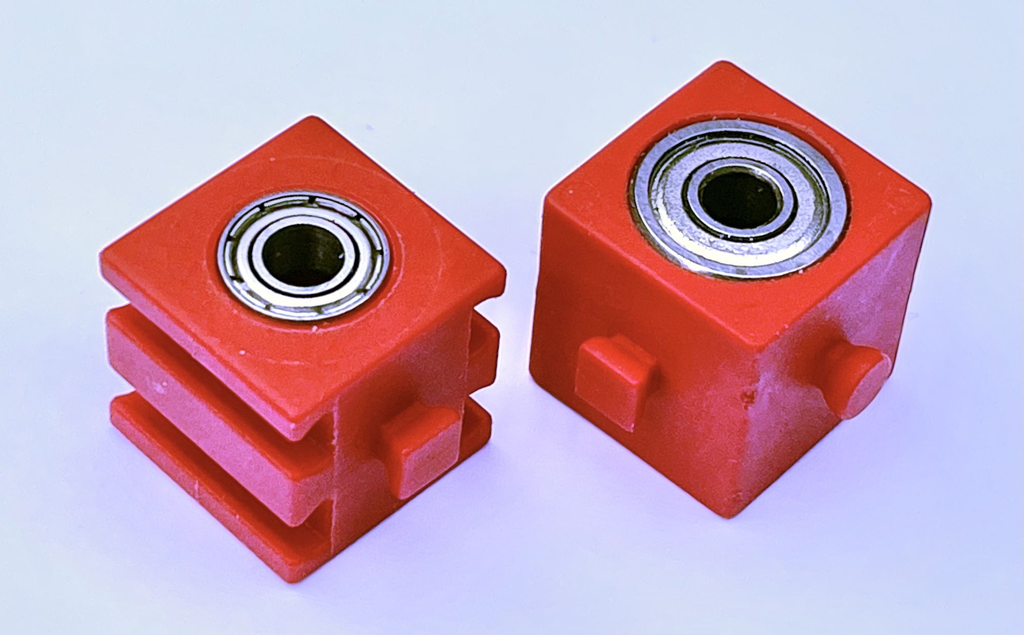
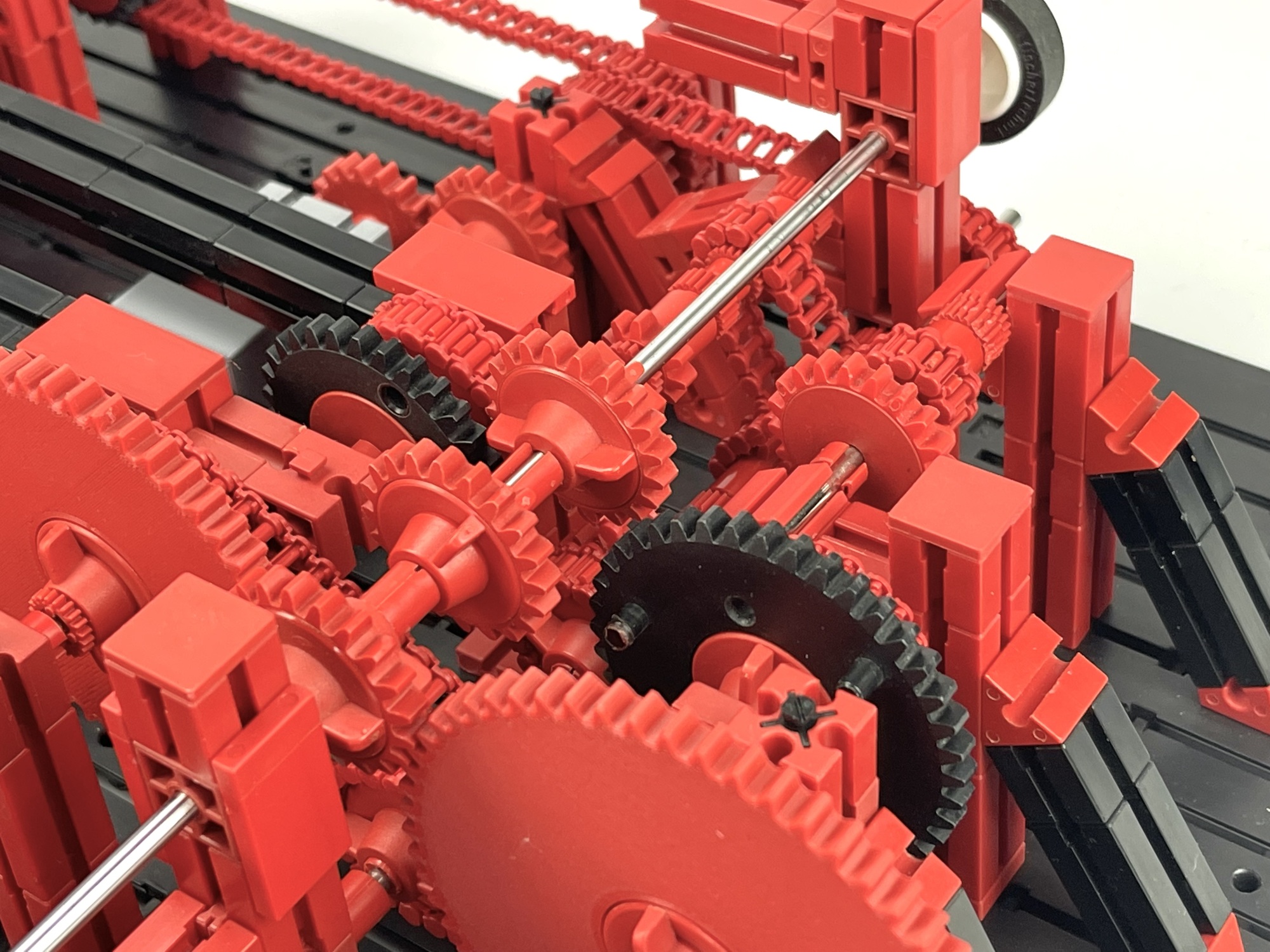
With the double gearbox it is possible to 'draw' the figures in a fully mechanical way. However, those who want to make two individually adjustable rotational speeds from one motor, as here, run into practical problems. The total number of gears ands transmission torque in the complete construction increased rapidly. The final mechanism of the double gearbox has no less than 58 gears and 16 chain transmissions! To limit the rotational resistance as much as possible, I therefore used ball bearings almost everywhere possible.
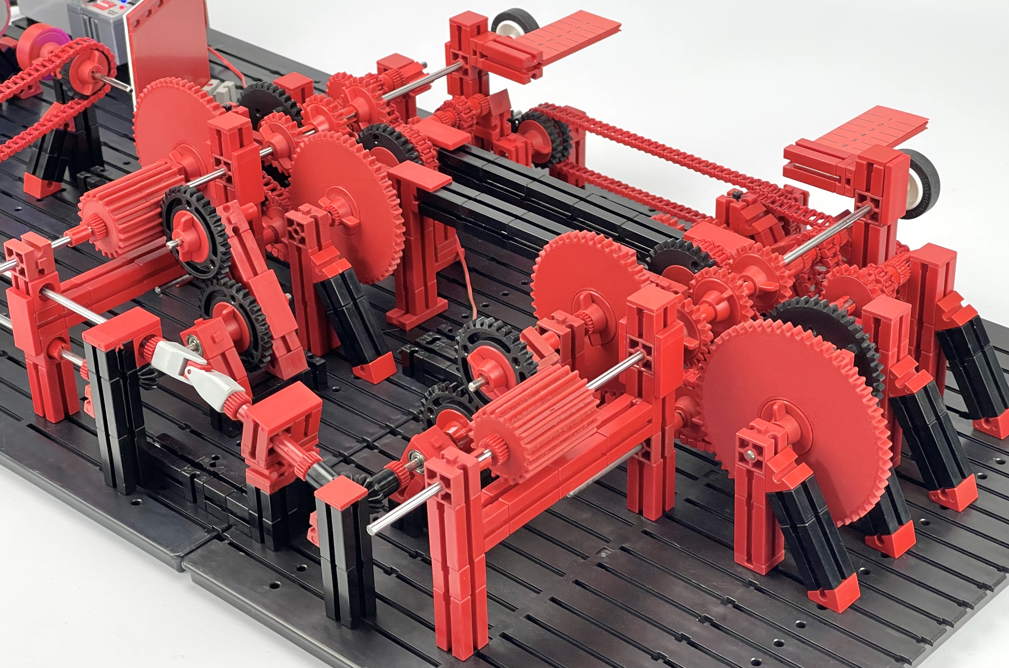
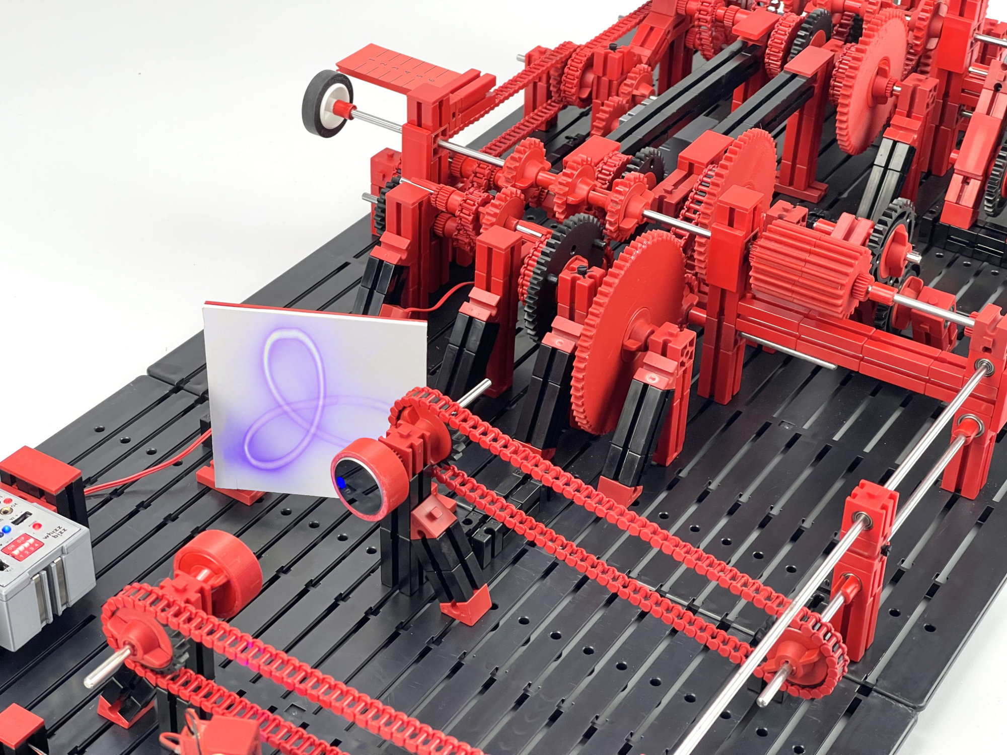
The adjustable transmission worked, and in itself produces stable 'stationary' figures because the individual rotational movements are derived from a single motor source. But with so many gears and chain transmissions, there was not enough torque left to significantly accelerate the rotational speeds of the mirrors. Because a relatively large amount of torque is lost, especially in the bevel gears, the mirrors rotate and oscillate at a speed of only 4 to a maximum of 25 Hz. Even the highest speed is too slow to achieve the 'persistence of vision' required for clearly recognizing the figures. The projection consists of a laser dot moving along the path of the figure. For the photos, that could be solved with a relatively long shutter speed. However, the figures are recognizable and it is clearly visible that the corner points of the Rose figure always fall exactly on the same point.
For a moment I considered working with for example paper on the projection screen, but it seemed more sensible to me, after this mechanical proof-of-concept, to carry out the control electronically.
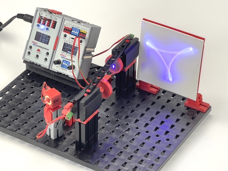
If the two mirrors can be driven directly by their own motor, their rotational speed can of course easily be individually controlled and increased considerably. To keep track of the different turning speeds (and especially the relationship between them), the challenge will shift to the speed controls. I opted for my Zauberling, which is already equipped for dual motor control.
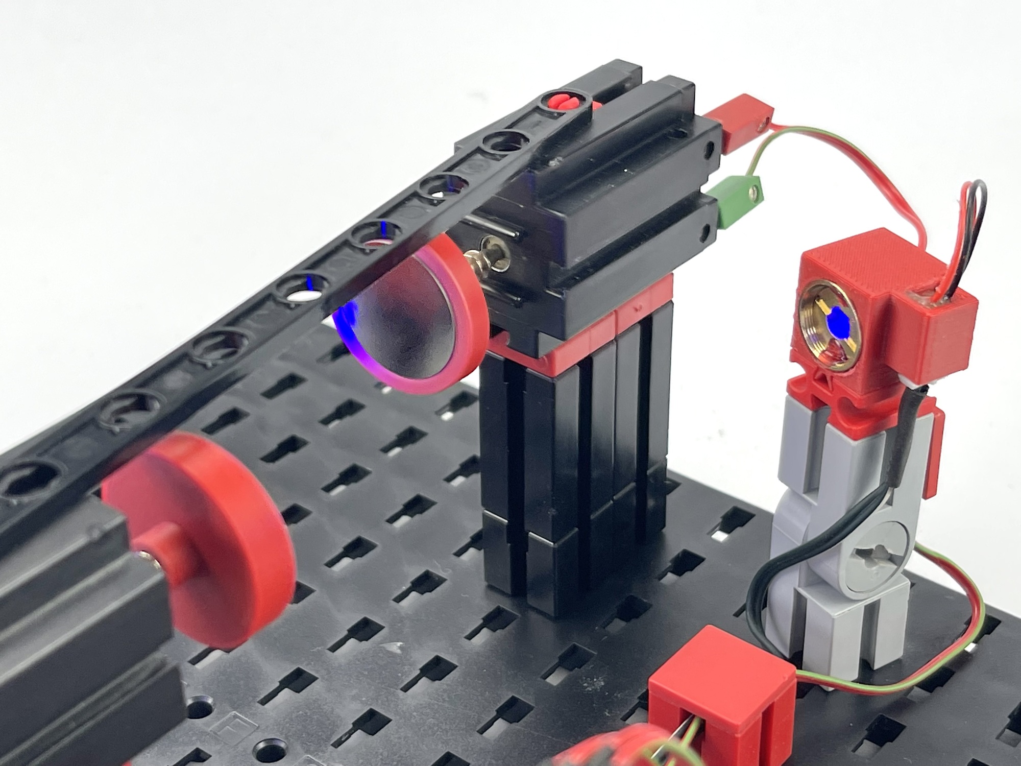
For mounting on the motor shaft, I chose small optical surface mirrors with a diameter of 20 mm. The 3D printed mirror tables have a mounting sleeve with a hole of 4.5 mm and fit directly on the worm shaft of a fischertechnik Mini or S motor. These self-printed parts are not necessary, it is also possible to mount the mirrors directly (temporarily) on the worm shaft of the motor with a large dot of glue from the glue gun.
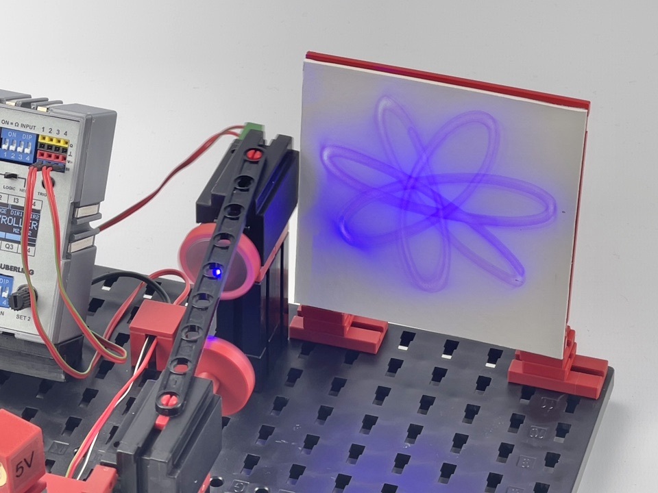
Although I expected that the projected figures would be unstable due to the use of two completely separate motors, it turned out to be quite easy to vary the rotational speed ratios in such a way that the various figures in Figure 3 were projected stably in practice. Moreover, the stepless variations made it possible to let them gradually transition into each other.
As expected, electronic control with a microcontroller simplifies the model considerably. The whole model fits on one small building plate now instead of several connected larger building plates. Still, both approaches have their own technical advantages and possible future experimental challenges. For example, it should not be forgotten that with the mechanical solution the two rotational speeds are derived from one underlying rotational speed by means of gear ratios. As a result, the projected figure is always stable and the rotational speed ratios follow very precisely the switched transmission ratios of the switched gears.
The rotational speed ratio of two motors with separate electronic control is obviously more difficult to synchronize. In principle, each motor is freewheeling with its own electromechanical properties, which means that phase changes will occur. The final projected figure can start spinning and twisting as a result. In most cases, manual fine-tuning then offered a solution, but a possible refinement could still be to adjust the motor control in such a way that the decisive rotational speed ratio can be controlled, instead of two individual rotational speeds. Another potentially useful future extension may be to minimize the drifting speed difference by measuring the actual measured rotational speeds and feeding that back to the motor control.
In order to prepare this in advance and to get a better impression of the exact mutual rotational speed ratio of the two separate motors, I already made a prototype of an rpm meter with an Arduino Uno and an LCD shield. IR obstacle sensors measure the passing of a reflective strip and the different speeds can be read on the display. I also immediately added a mode in which the gear ratio can be read directly from the display.
Measuring the actual rotational speeds of the two mirrors, or even feeding these values back into the control system, could be interesting follow-up projects.