With the classic fischertechnik 'Silberlingen', or its DIY variants, any digital circuit is quickly build. But eventually some 'load', such as a motor, will have to be driven from the digital output. Relays were traditionally used for this in the 1970s, but nowadays 'solid state' drivers with transistors or FETs are more common.
I was looking for a general solution for this for use with my DIY-'Silberlingen' and electronic modules. After all, it would be nice if we had a universal PCB that can be positioned at the bottom of casing and with which, if necessary, each digital output can be equipped with up to four short-circuit-proof and current-limited outputs.
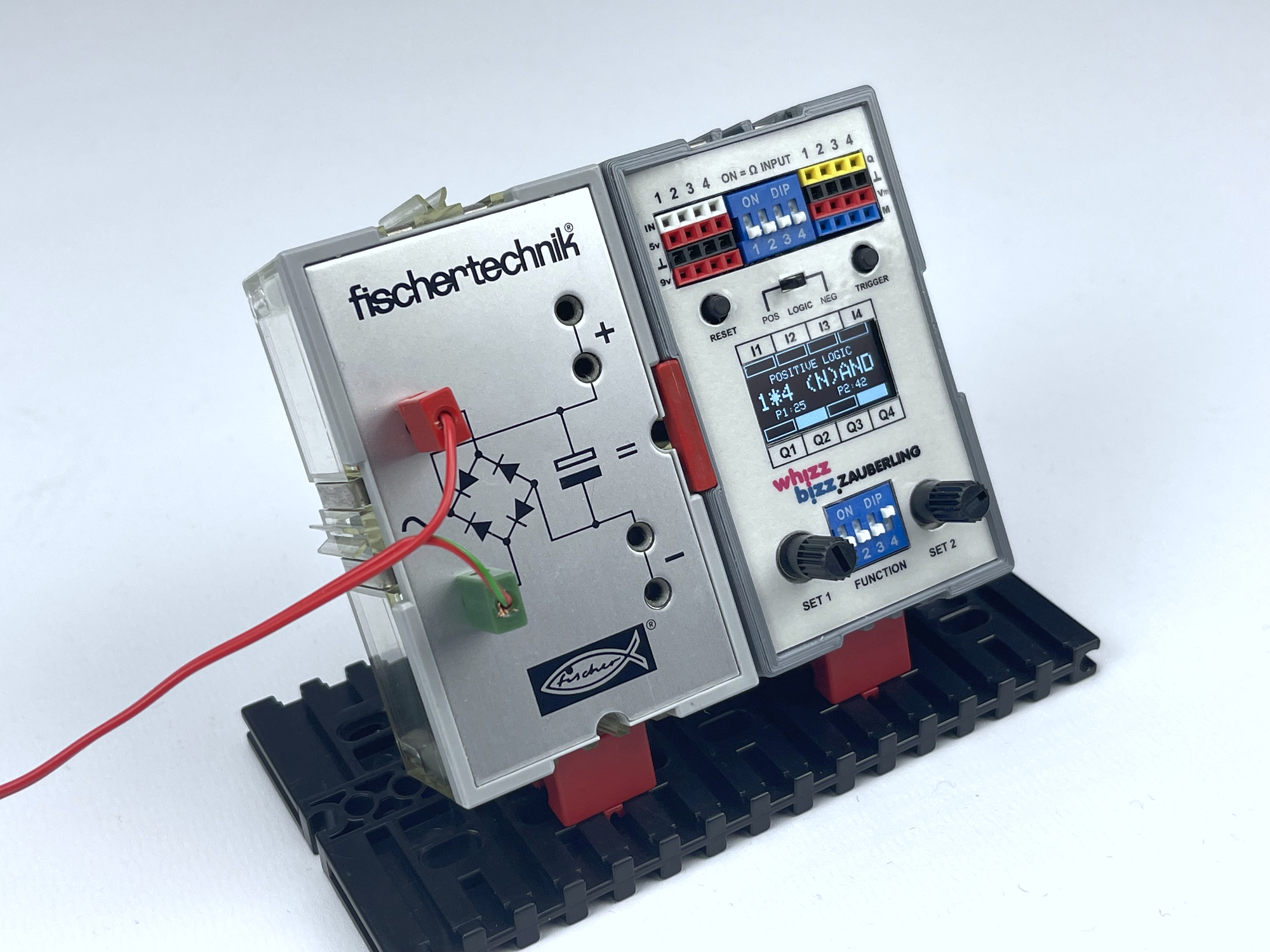
Anyone who has followed my tinkering here, and on YouTube, must have noticed that I enjoy making DIY modules that are fully compatible with these classic fischertechnik electronics modules: the 'Silberlings'. By 3D printing the case, they align in shape. But a starting point was also that modern and classic are compatible in terms of signal levels (around 11 volts). These classic modules from the 1970s made it possible to experiment with and prototype all kinds of circuits and electronic principles. There were flip-flops, mono-flops, a module with a signal amplifier for small sensor signals, and various logic gates such as AND/NAND and OR/NOR.
Because these classic electronic modules were completely made up of discrete electronic components that can only supply a small current, the output signal could essential only be used as a digital signal. So, when eventually a motor or a lamp had to be controlled, a relay module with a build in amplifier was often used.
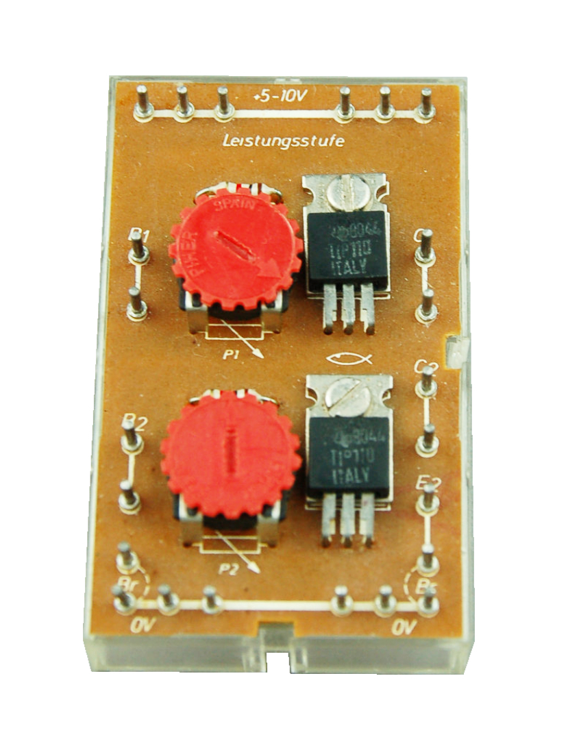
But later on, in the 'Electronics' and so called 'Praktikum' kits, they went more towards solid state drivers with semiconductors. For instance with the 'IC Baustein Leistungsstufe' LST 5-10V (fischertechnik nr. 36296) from the 'Elektronik' kit (nr. 30253) from 1981, for example, contained a module with two TIP110 darlington transistors. The switching threshold was adjustable with a potentiometer.
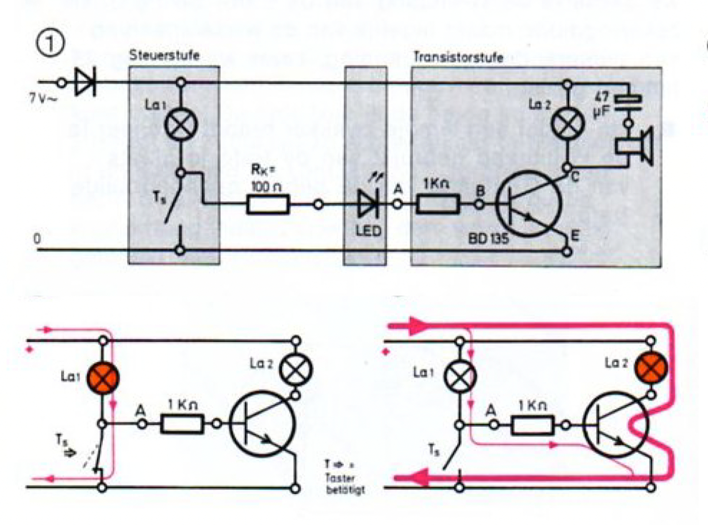
Even before, in 1977, the principle of current amplification was already explained with BD135 NPN transistors in the experiments of the 'Elektronik-Praktikum'. These experiments showed how lamps and motors could be supplied with sufficient current by amplifying with a transistor without the need for a relay.
The operation of such a driver with an NPN transistor is easy to explain. The load, a motor or lamp, etc., is connected between the positive supply voltage and the collector of the transistor. Without any switching input voltage, or as long as the base voltage remains below about 0.7 volts, the BD135 is closed and no current flows. But as soon as the voltage at the base of the transistor is high enough, or in other words as soon as we connect an 'active' or 'high' signal here, the collector to emitter path of the transistor opens and the motor will spin and the lamp will light up.
This method of controlling actors and loads from the 'Elektronik-Praktikum' is still very useful nowadays to control lamps, motors or pneumatic switches from the digital outputs of, for example, an Arduino or Raspberry microcontroller.
For the Mr. Lemniscate model, I wanted to switch two electromagnets from a flip-flop. So I built my own flip-flop with driver outputs for this then, just because I didn't want to do the control with relays. It seemed quite unnecessary to me, to add noise, delay and contact-wear by using a relay, which is in essence an electromagnetic switch, to power up other magnets. That's why I copied the original fischertechnik circuit diagram of the flip-flop, and built it together with two IRF520 MOSFETs in a fischertechnik cassette.
This was of course quite a quick and dirty proof of concept, but the idea of simply having an output on all these modules, that could supply just a bit more driving current, kept me busy. Because, lets face it, how nice would it be to have this kind of power outputs on any flip-flop, monoflop or for instance this DIY (N)AND/(N)OR gate, just if you need it? Wouldn’t it be possible to design some kind of universal printed circuit board to easily provide any DIY Silberling module with driver outputs? For instance a generic PCB that can then be placed at the bottom of the 3D-printed casing. Such a PCB, could then also accommodate the connectors neccesary for connecting and looping through the the external 12 volt power supply that feeds the driven motors and lamps etc.
It would be most convenient if such a driver module were equipped with a current limitation and a short-circuit protection. On Wikipedia I found an interesting article on current limiting that formed the basis for my own follow-up experiments.
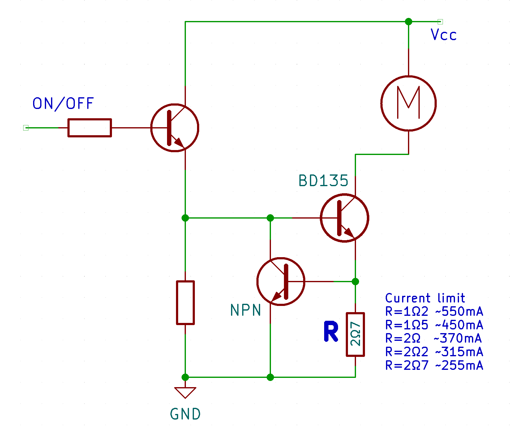
Because the measuring resistor has a fixed resistance value, we can calculate at which current that is with Ohm's law. For example, if we want to allow a maximum of about 250 mA current, then the following applies: [R = U/I = 0.7/0.260 = 2.7Ω] For a limitation at 255 mA, this would mean that we should include a resistor of 2.7Ω.
Note, however, that the power transistor is switched on and off at a high frequency during this 'current limiting'. As a result, heat is developed, which can destroy the transistor. Because this situation will of course never last that long in practice, the driver circuit is thus well protected and the power transistor better protected than without such a provision.
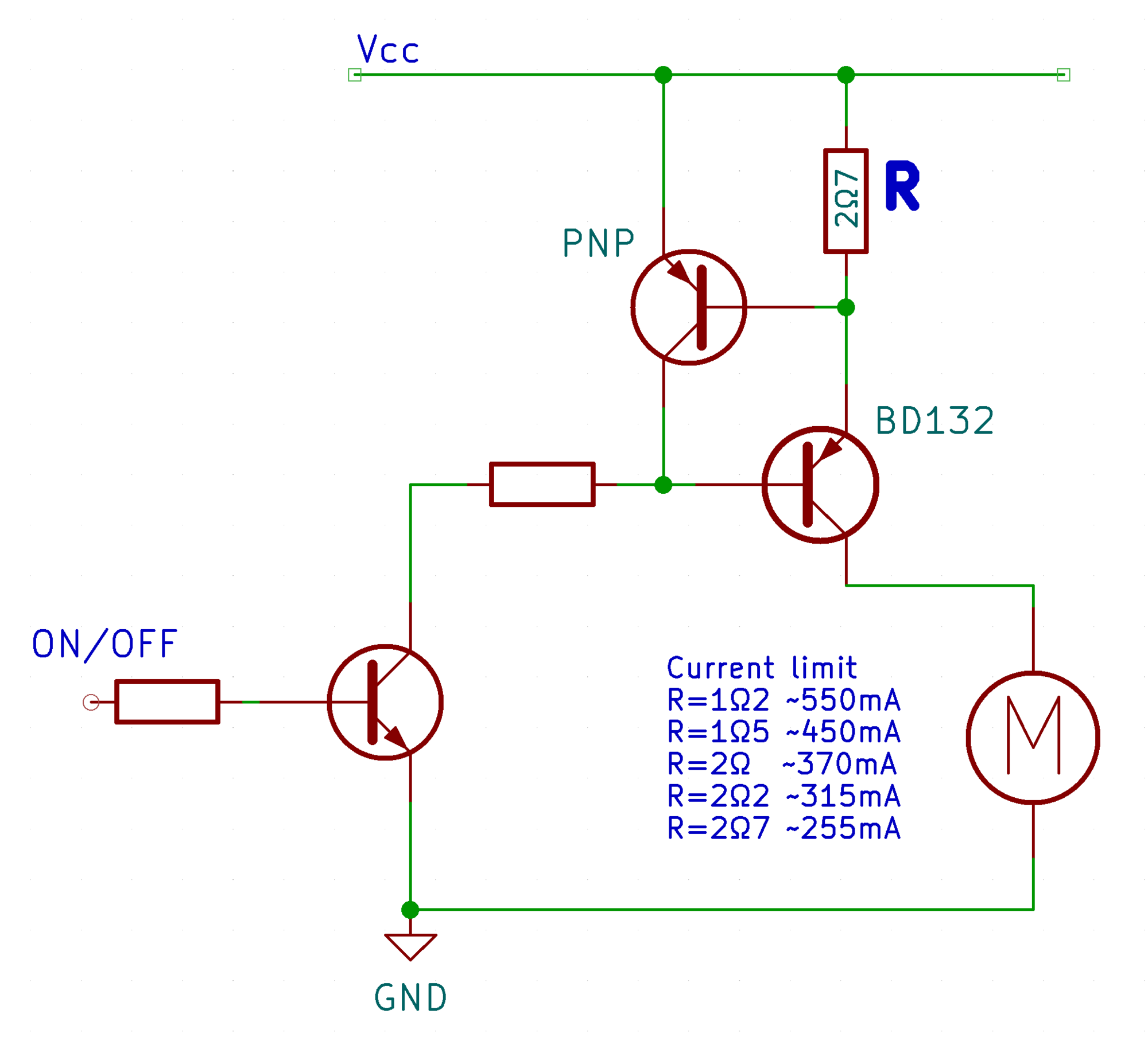
The motor or lamp must be connected between the plus and the collector of the driver transistor. It would be even more useful if the load could simply be connected between the output and ground. After all, the output could then also be used as a regular digital output and could also be used on (digital) inputs of other modules.
This is possible by choosing PNP transistors instead of NPN transistors and, for example, replacing the BD135 with a BD132. The circuit 'turns around' and we can give the connected users a common ground connection. See the modified circuit diagram.
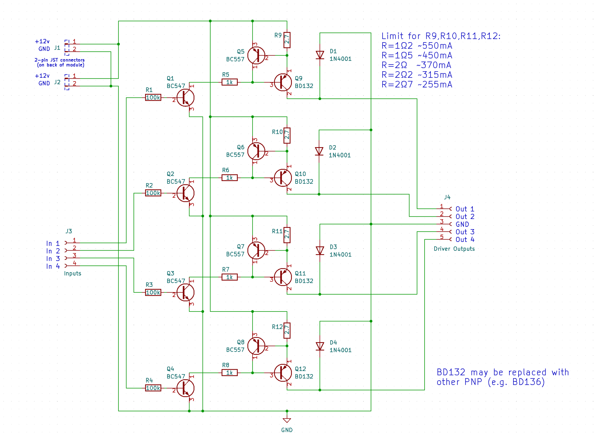
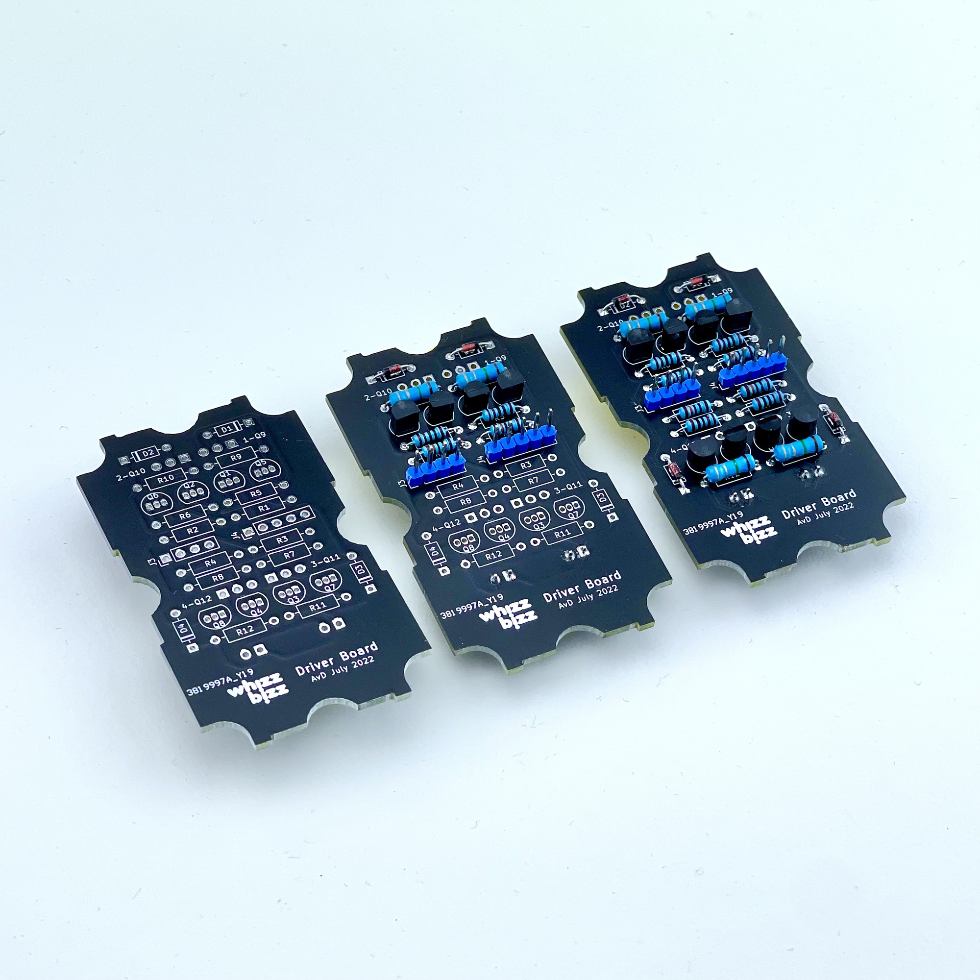
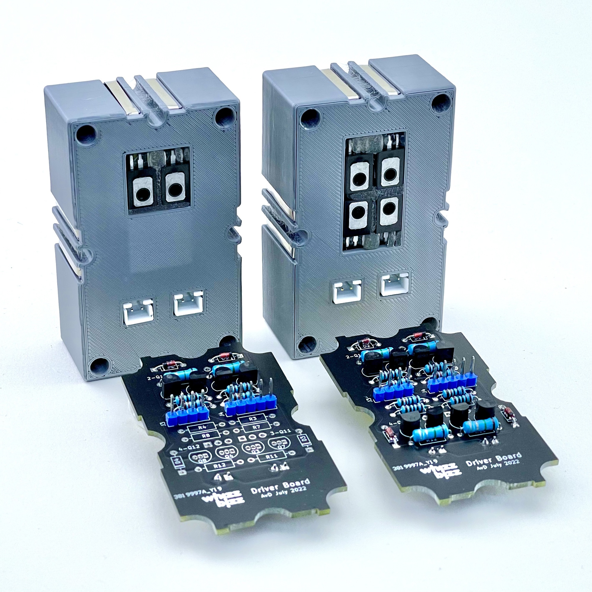
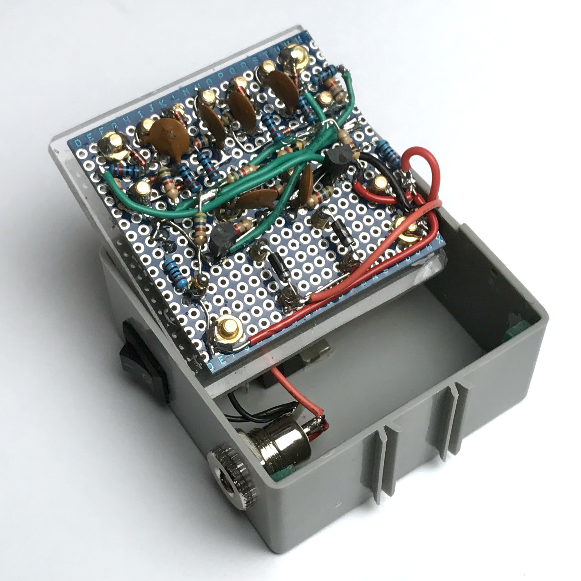
The available print space on a printed circuit board in a Silberling housing is not very large at 4 by 7 centimeters, but four of these circuits should certainly fit. I developed a universal printed circuit board with which I could add two or, if fully equipped with components, four driver outputs to my future electronics modules.
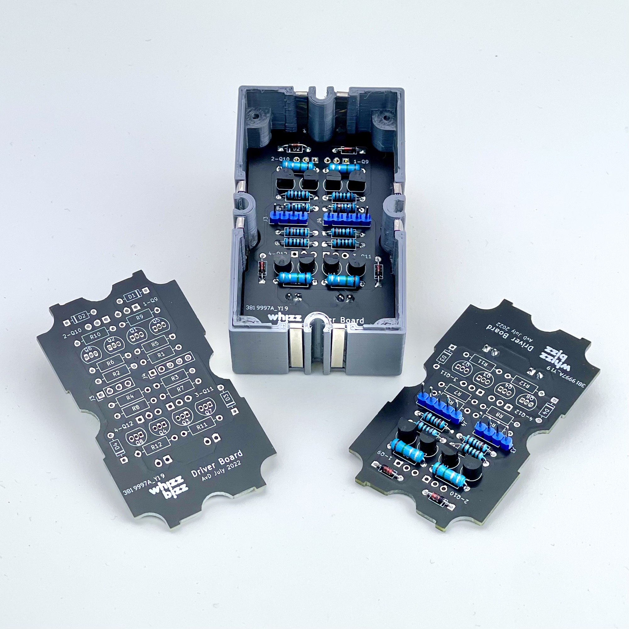
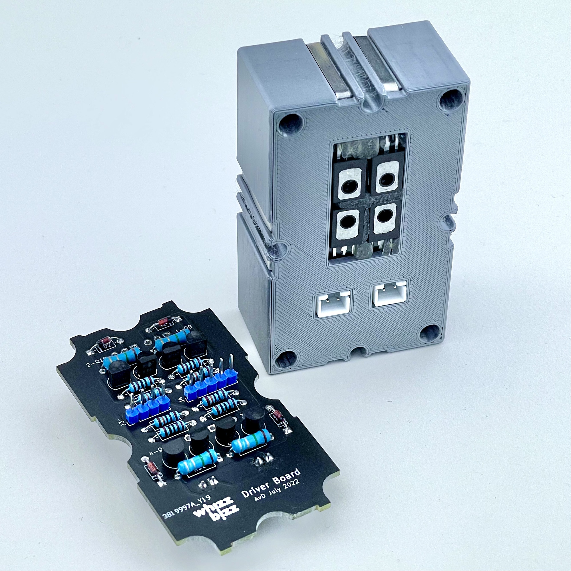
If the case has a 'window' on the back for two, or four, transistors in TO-126 package, they can always be cooled with a small heat sink if necessary. The power transistors are simply glued in place with a glue gun and later soldered when the PCB is mounted in the bottom of the housing.
The printed circuit board, at the bottom of the 3D-printed 'Silberling' housing, that was eventually developed can now quickly and easily add driver outputs to all my future DIY projects, if desired. It can be used directly in the reconstruction of the various classic fischertechnik 'Silberling' modules, such as the AND/NAND and OR/NOR logic gates.... But that is another project 😉