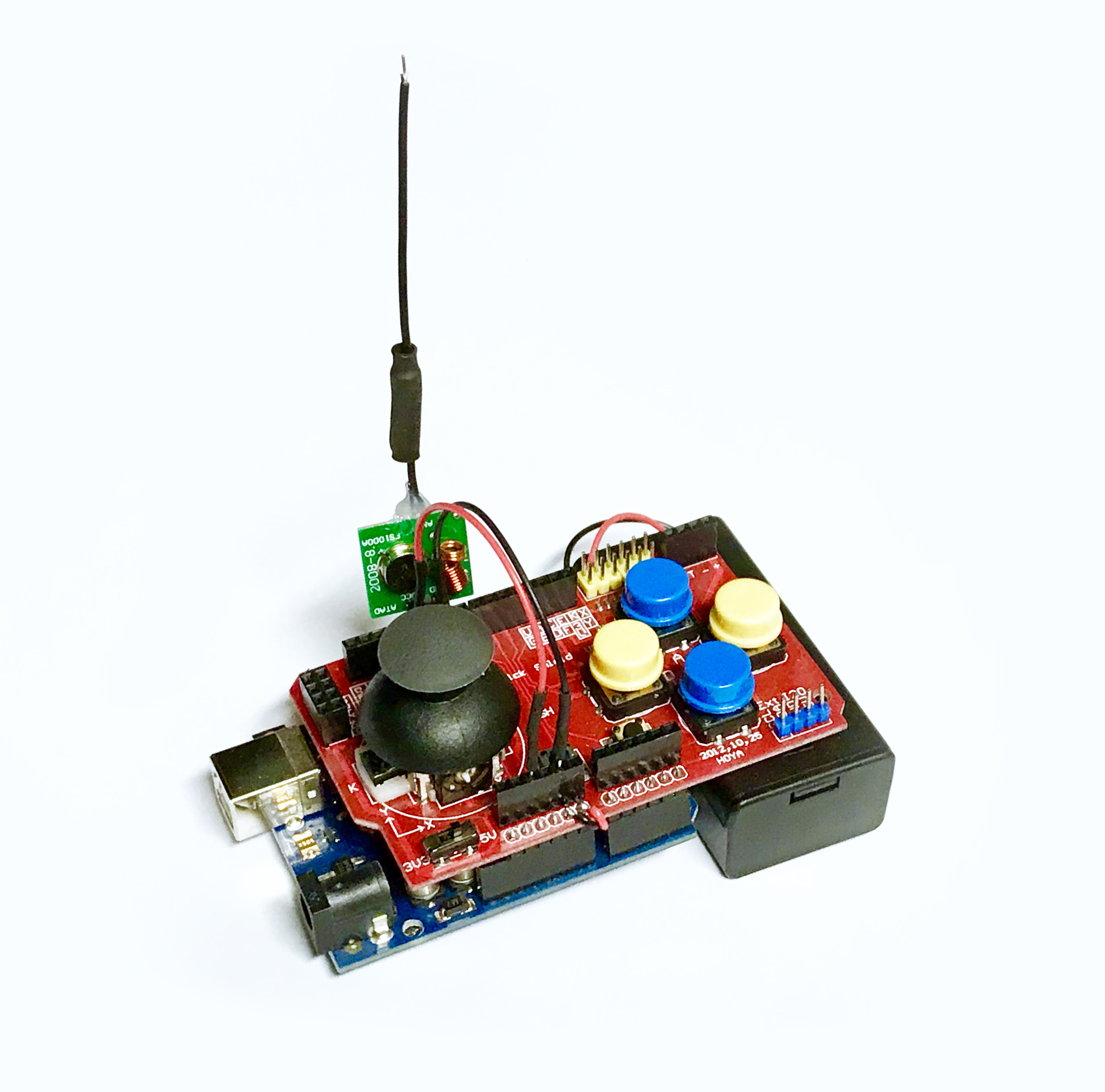
I also wanted to try the Joystick Shield from a previous project with a different type of transmitter and receiver. In various web shops I came across a very cheap set of modules for this. Actually, so cheap that it made me curious. They were sold for about 50 cents per module including shipping from China.
The soldering and assembly quality was indeed not good. So no high expectations. But when I played with it, it turned out not to be a bad buy and I even made a funny discovery!
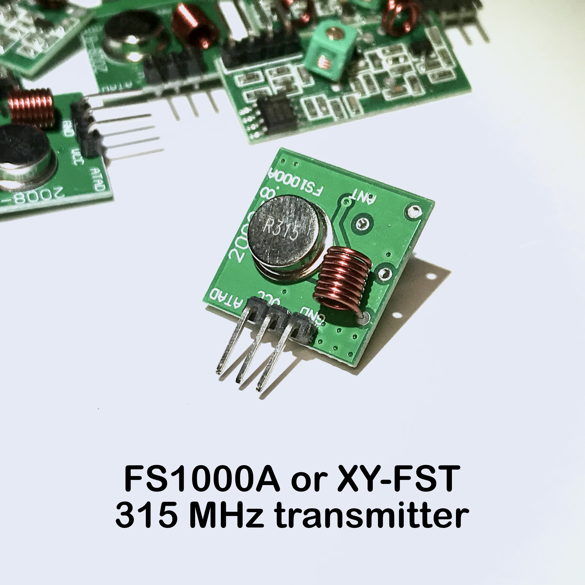
The FS100A transmitter module can be purchased dead cheap at various places. I also found these under the name "XY-FST", and in different variants. The crystal used to be the only difference. The variant with a 433MHz crystal seems the most common. It is mainly a coincidence that I ended up buying a set of six of these modules that work at 315MHz.
The transmitter is not really a miracle of technology for that price. The very small PCB also appears to be soldered quite carelessly. In any case, you have to solder an antenna to it yourself. A few unused holes are also noticeable, where parts seem to be missing! My confidence declined when I saw this more or less confirmed on various forums. This smelled like money down the drain.
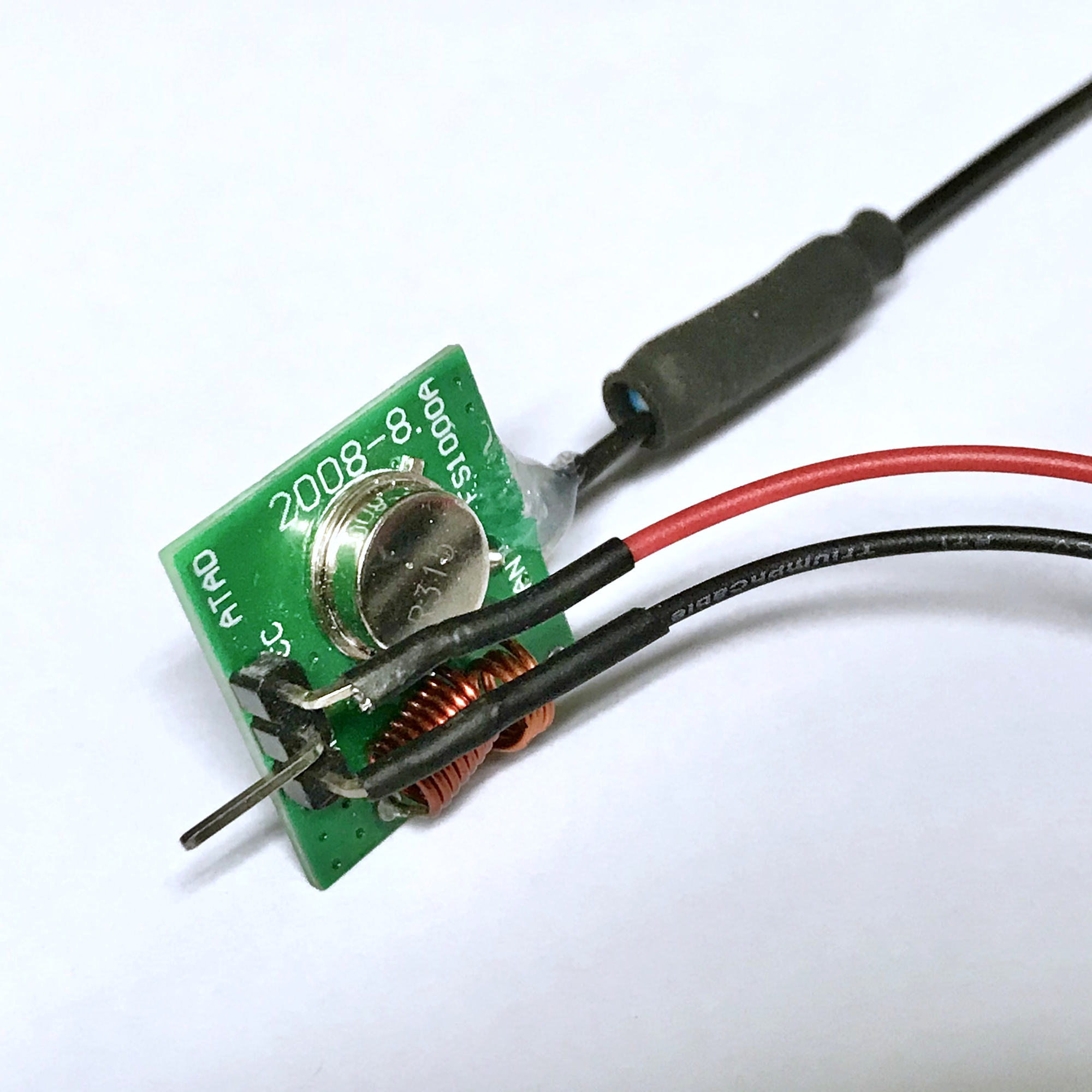
The circuit diagram found for this transmitter is very simple, but the apparently missing coil does seem essential in this. The transmitter consists of a simple oscillator built around a crystal that is switched on and off (modulated) in the rhythm of the data to be sent. This is called 'Amplitude Shift Keying' (ASK). No error correction or channel settings possible, so using several of these PCBs in one location will be difficult, I think. But what do you expect for such a price?
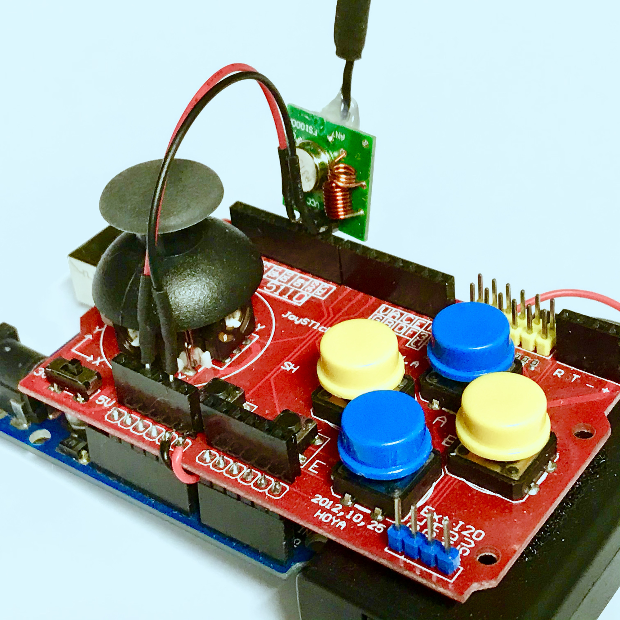
As a precaution, I immediately wound and mounted the missing coil (2.5 windings) and checked all soldering. The next step was the antenna. First of all, a solder-filled and too small hole had to be carefully drilled wider for this. For the 433MHz transmitters (with wavelength λ of 69 cm) the length of a possible antenna wire of 1 / 4λ = 17.3 cm. But since my crystal clearly stated '315', I made an antenna for both transmitter and receiver for 315MHz. A simple wire of a quarter of the wavelength (1 / 4λ = 23.8 cm) is sufficient, but to make it shorter I chose a coil winding in the middle. It seemed useful to me to strengthen things a bit with some heat shrink tube and to relieve the soldering a bit by securing the antenna to the PCB with a drop of hot glue.
I provided the pins for the power supply with separate wires. The data input of the module can be plugged into output 9 of the joystick shield. In this case this is on the edge connector of the possible Nokia display or the nRF24L01 transceiver module, but neither was in use in this case. If these SPI ports on the joystick shield are used, only A2 and A3 will remain as possible inputs to be used for this.
// Arnoud, last day of 2020 and further :-)
// Uses RadioHead lib for XY-FST/XY-MK-5V combi: http://www.airspayce.com/mikem/arduino/RadioHead/RadioHead-1.113.zip
//
#include "RH_ASK.h"
#include "SPI.h"

#define DEBUG

// XY-FST defines...
#define XYFST_PIN  9

#define button_A  2 // Button Blue - A
#define button_B  3 // Button Yellow - B
#define button_C  4 // Button Blue - C
#define button_D  5 // Button Yellow - D
#define button_E  7 // SMD button E on pcb
#define button_F  6 // SMD button F on pcb
#define button_joystick 8 // Button in joystick
#define x_axis A0
#define y_axis A1
int buttons[]={ button_A, button_B, button_C, button_D, button_E, button_F, button_joystick };
int joystick[9]; // Array holding state of buttons and joystick X- and Y-reading

// RH_ASK driver(speed, receive-pin, transmit-pin, push-to-talk:not needed)
RH_ASK driver(2000, NULL, XYFST_PIN, NULL); // ESP8266 or ESP32: do not use pin 11

void setup(){
#ifdef DEBUG
  Serial.begin(115200);
#endif

  for (int i=0; i <7 ; i++) {
    pinMode(buttons[i], INPUT_PULLUP);
    digitalWrite(buttons[i], HIGH);
  }

  // Setup XY-FST...
  if (!driver.init())
    Serial.println("Transmitter XY-FST init failed");
  else
    Serial.println("Transmitter XY-FST success");
}

void loop() {
  // Read digital buttons...
  for (int i=0; i <7 ; i++)
    joystick[i] = digitalRead(buttons[i]);

  // Read joystick values...
  joystick[7] = analogRead(x_axis);
  joystick[8] = analogRead(y_axis);

  // Write out values array...
  driver.send((uint8_t *)joystick, sizeof(joystick));
  driver.waitPacketSent();
  delay(200);

#ifdef DEBUG
  // Log...
  for (int i=0; i <9 ; i++) {
    Serial.print(joystick[i]);
    if (i<8)
      Serial.print(", ");
  }
  Serial.print("\n");
#endif
}
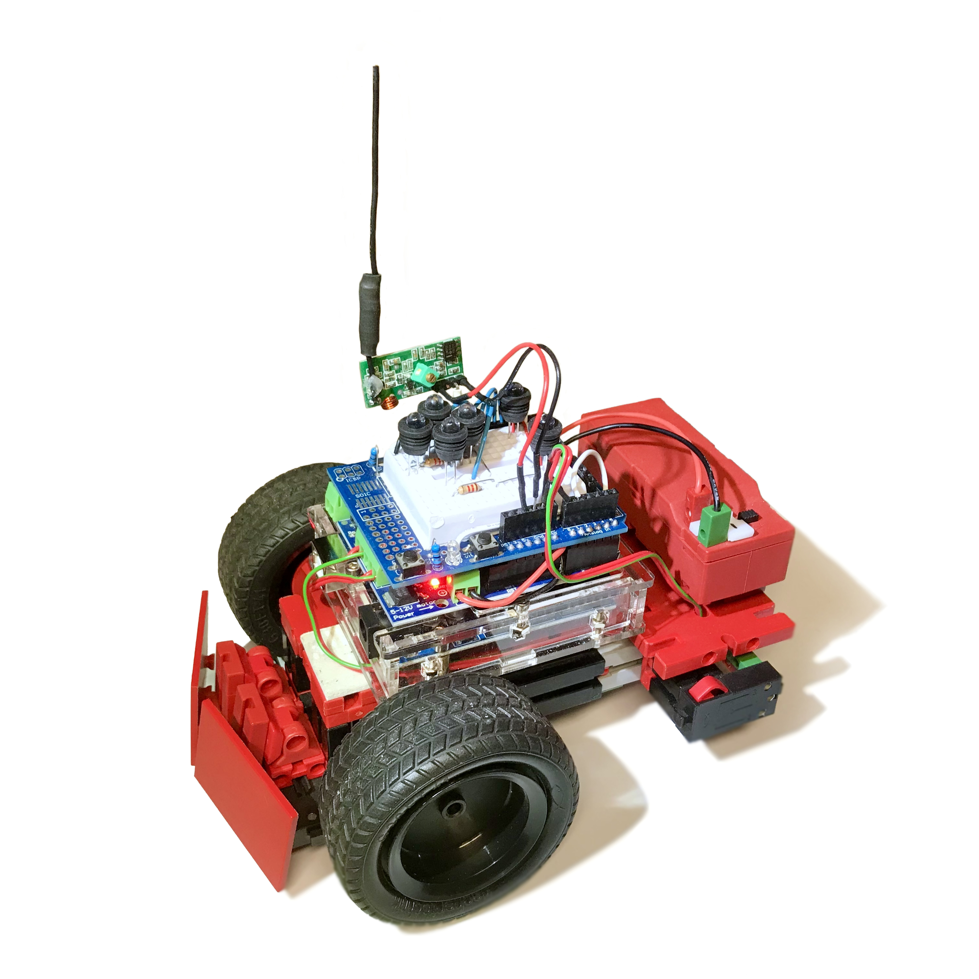
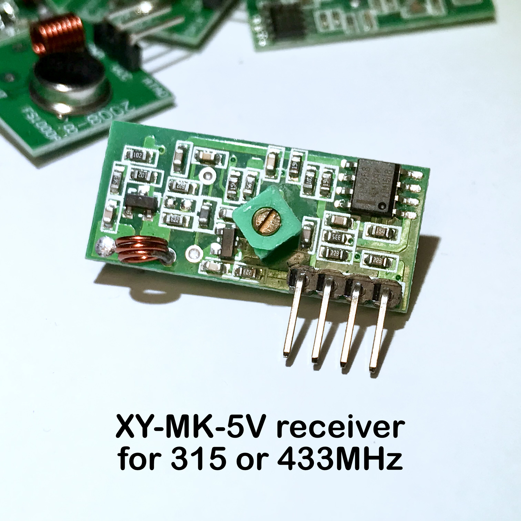
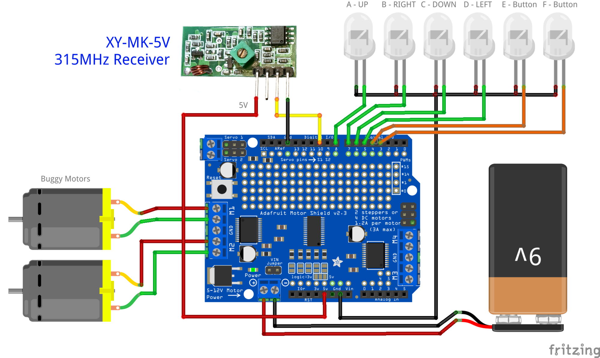
The supplied receiver seems to be exactly the same for both the 315MHz and the 433MHz variants of the transmitter. The setting will have been made with the coil trimmer on the PCB. I didn't mess with that, and only connected an antenna. The receiver is connected to input D10, but it can be connected to any free digital input.
Below the connection diagram on a motor shield. I just reused the test setup on the prototype board of the previous experiment with the LEDs for this remote control test. Connecting directly to your Arduino is of course also possible.
The data communication between the modules is very rudimentary. Simply 8-bit bytes are written from the joystick shield that modulate the 315MHz carrier wave. These are picked up by the receiver and 'translated' to the same 8-bit bytes as digital levels on input D10 of the receiver Arduino. Since I wanted to transfer integer values between 0 and 1023 for the joystick positions, I just combined two bytes into one 16 bit word in the Sketches for the sender and receiver. This is quite an overkill for the push status of the buttons (0 or 1), but it simplified the principle. Those who want to optimize the data traffic could simply take all buttons together in one byte when sending.
// Arnoud, last 12-01-2021
// Uses RadioHead lib for XY-FST/XY-MK-5V combi: http://www.airspayce.com/mikem/arduino/RadioHead/RadioHead-1.113.zip
//
// Connect motors (Adafruit Motor Shield):
//    Left Motor: MotorL (M1)
//    Right Motor: MotorR (M2)

#include "RH_ASK.h"
#include "SPI.h"
#include "Adafruit_MotorShield.h"

#define DEBUG // Outcomment for stealth/live operation...

// XY-MK-5V defines...
#define XYMK5V_PIN  10

// Various defines...
#define LED_A 8  // Button A
#define LED_B 7  // Button B
#define LED_C 6  // Button C
#define LED_D 5  // Button D
#define LED_E 3  // Button E
#define LED_F 4  // Button F
#define LED_K 2  // Joystick button
#define SEND_BUTTON A1 // Switch to test talking back to joystick shield...
#define MaxSpeed 255   // Max motor speed
#define safeRange 50   // Safe range to ignore round midpoint of joystick readings...
#define Baudrate 115200

int leds[] = { LED_A, LED_B, LED_C, LED_D, LED_E, LED_F, LED_K };
int sendbutton;
int joystick[9]; // Communications array holding state of buttons and joystick X- and Y-reading
uint16_t value;  // Momentary joystick value...
int dirMotorL = FORWARD;
int dirMotorR = FORWARD;
int motorSpeedL = 0;
int motorSpeedR = 0;
int speedDiff = 0;
int i; // Counter...

// RH_ASK driver(speed, receive-pin, transmit-pin, push-to-talk:not needed)
RH_ASK driver(2000, XYMK5V_PIN, NULL, NULL); // ESP8266 or ESP32: do not use pin 11
Adafruit_MotorShield MShield = Adafruit_MotorShield(0x60);
Adafruit_DCMotor *MotorL = MShield.getMotor(1); // Left motor
Adafruit_DCMotor *MotorR = MShield.getMotor(2); // Right motor

bool buggyBusy = false;

void buggycontrol() { // Control the Buggy
  buggyBusy = true;

  // Show feedback with LEDs and log to serial during debug...
  for (int i=0; i <9 ; i++) {
    if (i<7) {
     if (joystick[i]==1)
       digitalWrite(leds[i], LOW);
     else
       digitalWrite(leds[i], HIGH);
    }
#ifdef DEBUG
    Serial.print(joystick[i]);
    if (i<8)
      Serial.print(", ");
#endif
  }
#ifdef DEBUG
  Serial.print("\n");
#endif

  // Determine (signed/directional) speed based on Y-axis joystick value reading,
  // ignore range around midpoint (theoretically 512) to prevent unwanted jitter...
  motorSpeedL = motorSpeedR = 0;
  if (joystick[8] < 512-safeRange) {
    motorSpeedL = map(joystick[8], 0, 512, -MaxSpeed, 0);
    motorSpeedR = motorSpeedL;
  } else if (joystick[8] > 512+safeRange) {
      motorSpeedL = map(joystick[8], 512, 1023, 0, MaxSpeed);
      motorSpeedR = motorSpeedL;
  }

  // Determine relative (signed/directional) curve-/turn-speed difference based on X-axis reading,
  // ignore range around midpoint (theoretically 512) to prevent unwanted jitter...
  speedDiff = 0;
  if (joystick[7] < 512-safeRange) {
    speedDiff = map(joystick[7], 0, 512, -255, 0);
  } else if (joystick[7] > 512+safeRange) {
      speedDiff = map(joystick[7], 512, 1023, 0, 255);
  }
  motorSpeedL = (motorSpeedL+speedDiff);
  motorSpeedR = (motorSpeedR-speedDiff);

  // Determine direction per motor...
  dirMotorL = FORWARD;
  dirMotorR = FORWARD;
  if (motorSpeedL<0) dirMotorL = BACKWARD; // Reverse...
  if (motorSpeedR<0) dirMotorR = BACKWARD; // Reverse...

  // Crop and absolutize motorspeeds...
  motorSpeedL = abs(motorSpeedL);
  motorSpeedR = abs(motorSpeedR);
  if (motorSpeedL>MaxSpeed) motorSpeedL = MaxSpeed;
  if (motorSpeedR>MaxSpeed) motorSpeedR = MaxSpeed;

#ifdef DEBUG
  Serial.print("\nmotorSpeedL = ");
  Serial.print(motorSpeedL);
  Serial.print(", motorSpeedR = ");
  Serial.print(motorSpeedR);
  Serial.print(", speedDiff = ");
  Serial.print(speedDiff);
  Serial.print(", dirMotorL=");
  Serial.print(dirMotorL);
  Serial.print(", dirMotorR=");
  Serial.print(dirMotorR);
  Serial.print("\n");
#endif

  MotorL->run(dirMotorL);
  MotorR->run(dirMotorR);
  MotorL->setSpeed(motorSpeedL);
  MotorR->setSpeed(motorSpeedR);

  buggyBusy = false;
}

void setup() {
#ifdef DEBUG
  Serial.begin(Baudrate); // Start serial monitor...
#endif

  // Setup LEDs...
  pinMode(LED_A, OUTPUT);
  pinMode(LED_B, OUTPUT);
  pinMode(LED_C, OUTPUT);
  pinMode(LED_D, OUTPUT);
  pinMode(LED_E, OUTPUT);
  pinMode(LED_F, OUTPUT);
  pinMode(LED_K, OUTPUT);
  pinMode(SEND_BUTTON, INPUT_PULLUP);

  MShield.begin(); // Motor Shield initialize...
  Wire.setClock(400000); // Set I²C-Frequenz at 400 kHz

  // Initialize motors...
  MotorL->setSpeed(motorSpeedL);
  MotorR->setSpeed(motorSpeedR);

  // Blink that we're alive: all LEDs on...
  digitalWrite(LED_A, HIGH);
  digitalWrite(LED_B, HIGH);
  digitalWrite(LED_C, HIGH);
  digitalWrite(LED_D, HIGH);
  digitalWrite(LED_E, HIGH);
  digitalWrite(LED_F, HIGH);
  digitalWrite(LED_K, HIGH);

  if (!driver.init())
    Serial.println("XY-MK-5V receiver init failed");
  else
    Serial.println("XY-MK-5V receiver init success");
  delay(2000); // Signal power-up...

  // Blink: all LEDs off...
  digitalWrite(LED_A, LOW);
  digitalWrite(LED_B, LOW);
  digitalWrite(LED_C, LOW);
  digitalWrite(LED_D, LOW);
  digitalWrite(LED_E, LOW);
  digitalWrite(LED_F, LOW);
  digitalWrite(LED_K, LOW);
}

void loop() {
  uint8_t buf[RH_ASK_MAX_MESSAGE_LEN];
  uint8_t buflen = sizeof(buf);

  if (driver.recv(buf, &buflen)) { // Non-blocking
    if (buflen==18) { // Only if 9 words where received...
      for (i=0; i<9; i++) // Consolidate received values in joystick array...
        joystick[i] = buf[(2*i)+1] << 8 | buf[(2*i)];
    }
  }

  if (!buggyBusy)
    buggycontrol(); // Control the Buggy...

#ifdef DEBUG
  // Log...
  for (int i=0; i <9 ; i++) {
    Serial.print(joystick[i]);
    if (i<8)
      Serial.print(", ");
  }
  Serial.print("\n");
#endif
}
The prepared set actually worked immediately without any problems. This of course made me curious about the other five modules. A big surprise was that these just worked as is! Without the supposedly missing coil! After reading all the experiences, assumptions (and even accusations) of fellow buyers on the internet, this came as quite a surprise!
The solution turns out to be simple. The coil is just there and the oscillator transistor is 'powered' neatly. On my version of the modules it is a smd coil (or wire bridge by means of 0Ω resistor?) on the bottom of the print. The open holes are (in my case) completely harmless. In the worst case, I now have a PCB in use with two coils in parallel, but that doesn't seem a problem because this coil probably only is for HF decoupling of the supply voltage.
So the lesson is again: don't worry and just test it first. All transmitter modules worked, which is perhaps the advantage of such a very simple structure. But putting an antenna on it seems worthwhile. The tested modules without antenna wire had a poor range. With an antenna wire it works fine, and I can imagine that the transmission power and the achievable range at 12V will be completely excellent.
This was the proof-of-concept of this type of transmitter. That is why the test Buggy with LEDs came in handy again. The control is, as becomes clear from the video, in itself fine. Although the response speed seems to lag a bit behind the 2.4GHz nRF24L01 from the previous test. And with that tranceiver, a full full-duplex connection was also possible.
For real-time control of driving or flying models I might not use this 315MHz transmitter, but if you are looking for a very cheap solution for the wireless transmission of data (e.g. from a weather station or other sensor or detector information) it can certainly be a useful little thing. Note: no channels to be set. The second transmitter at the same location will then have to be a 433MHz model to avoid interference, I guess. Why they are sold by half a dozen is therefore not entirely clear. Maybe someone wants to exchange a 315Mhz set for a 433MHz set with me? 😄