
An external 12-volt adapter can be connected to the back of the Zauberling. Connecting the adapter directly to the module, an on/off button and getting a better view of the power consumption of the standard supply voltages (3.3, 5, 9 and 12 volts) remained separate wishes for the future.
Read here how things can get completely out of hand when you do get into tinkering. The Ultimate Multi Power Module is small (3.5 by 7 cm!) and offers four power supply voltages. Voltage, (peak) current and power are monitored per output. Hopefully there is even room for a programmable automatic fuse!
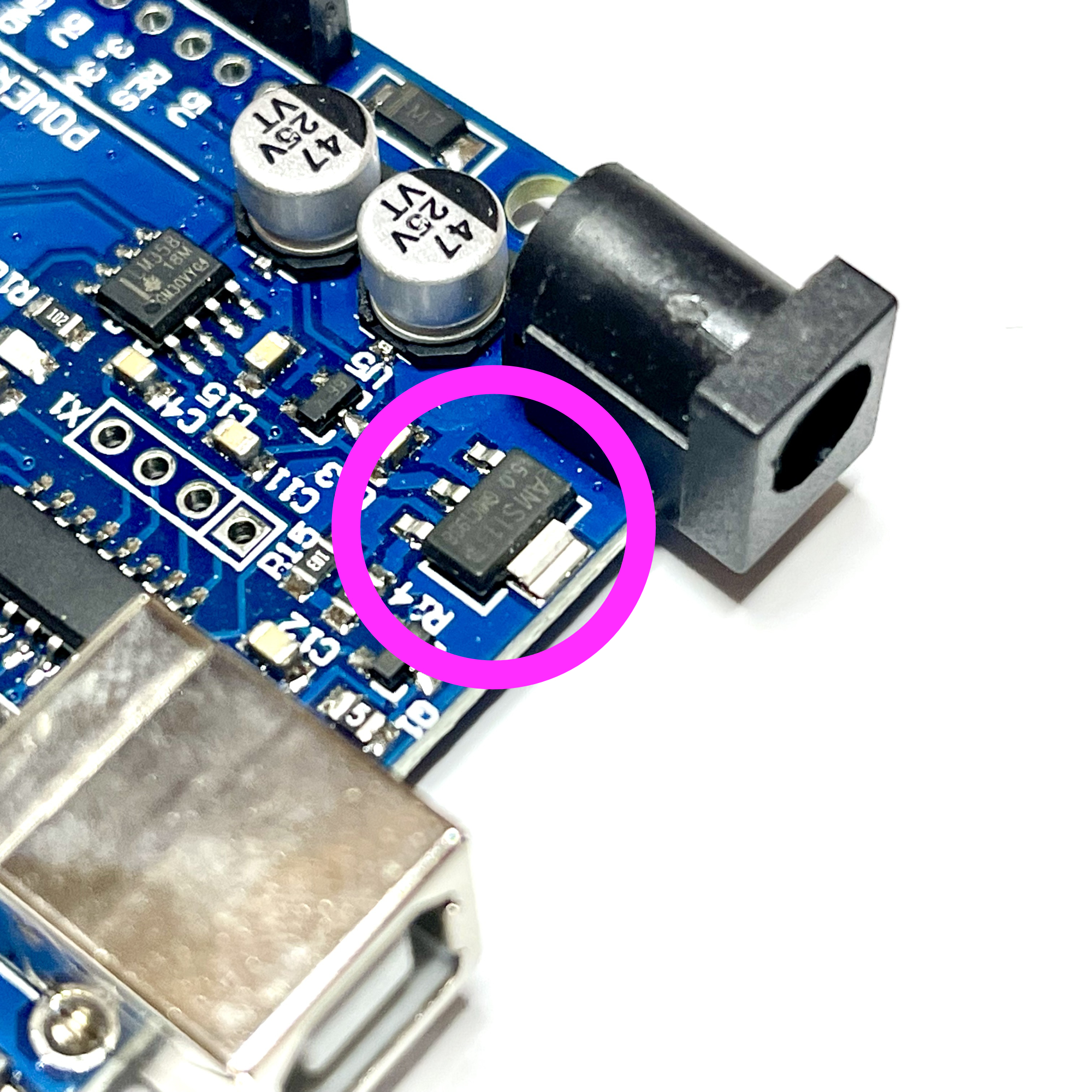
Most microcontroller boards have their own 'voltage regulator' on the PCB. The component generates the necessary 5, or 3.3 volts from a higher supply voltage. Handy, because that way you can just use a 9 volt adapter to power your Arduino and also feed some additional project electronics, such as a display, with the 5 volts created on the Arduino board.
However, even if this combined current requirement remains below 100mA, significant heat can actually be generated in the regulator. Something to keep an eye on! Especially if the power requirement increases, it seems more sensible to bypass the regulator on the board and to power all kinds of peripheral equipment directly from an external voltage source. This relieves the microcontroller of unnecessary heat generation and perhaps opens up possibilities to monitor and control the current, voltage and power, etc.
Anyone who ever experiments with Arduinos, or for example fischertechnik models, will sooner or later need something that can easily provide multiple ready-made supply voltages. For example, to connect an external sensor, it is easy to have 3.3 volts available. Or it is convenient to offer 9 and 12 volts during experiments with other external electronics.
Such a module would be useful for powering the controlling controller such as a Zauberling module. It would also be useful during experiments in the electronics workshop. Especially if, for example, there would be features such as reading of the voltage and current or an automatic fuse.
This day dreaming quickly led to a wish list of the possibilities of such an Ultimate Multi Power Module:
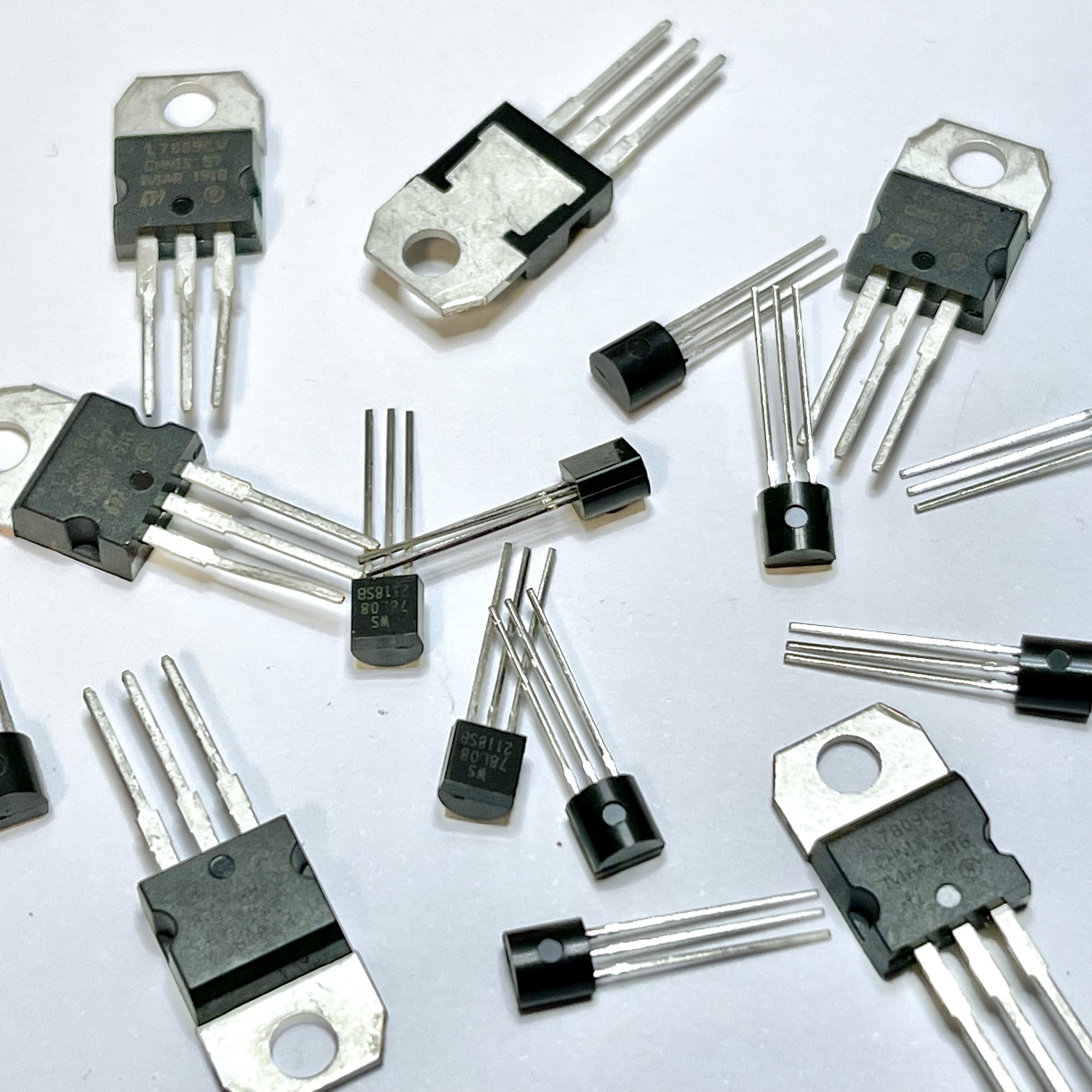
Our module will soon have to make various supply voltages and voltage regulators are therefore widely used. A disadvantage is that they dissipate the excess voltage in heat, so that a heat sink may be required at higher currents, or rather higher powers of heat. The 7805 voltage regulator that makes 5 volts out of 12 volts needs to get rid of 7 volts. As a result, at a current of 500mA, 3.5 W of heat will have to be dissipated.
However, the ultimate delivered currents of the Ultimate Multi Power Module, especially if they can be properly monitored, are likely to be limited. And for example for the 3.3 volts a small SMD regulator of maximum 100mA would even suffice. This makes the use of voltage regulators obvious, but I first investigated a few other, partly ready-made, solutions that work in a different way.
A more efficient solution in principle would be a switching power supply; a so-called buck converter. This first makes an alternating voltage from the offered direct voltage, which is then converted back to the desired direct voltage. A disadvantage is that this requires some additional parts, such as a coil. There are many small power modules available today with the LM2596; a well-known Step-Down Voltage Regulator that can deliver up to 3A of current with significantly less heat generation than traditional voltage regulators.
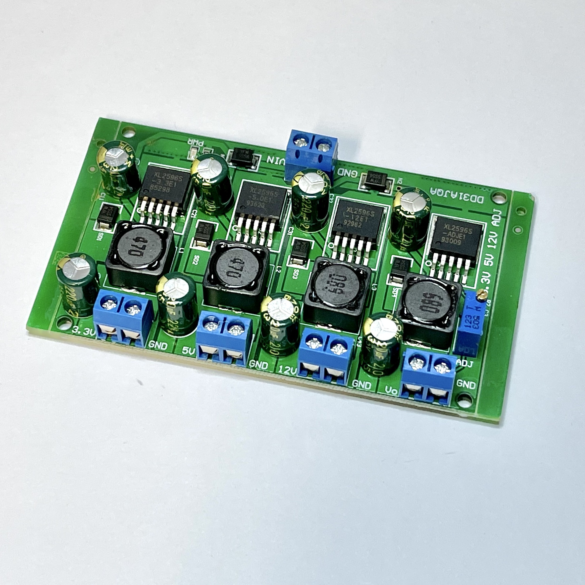
The product information and datasheet of the LM2596 tells us that there are four versions of this chip. There are versions for the voltages 3.3, 5 and 12 volts. And an adjustable one whose output voltage can be regulated with an external potentiometer. For less than ten euros, I bought a module that contains all these models! The 3.3, 5, 12 variant of the chip and the adjustable variant of the LM2596 are conveniently brought together on one PCB.
The LM2596 can only convert up, so the input voltage will have to be at least 1.5 volts higher than the requested output. With an input voltage of 15 volts, and the adjustable LM2596 tuned to 9v, all desired voltages can be made quite easily.
Unfortunately, this module only covers part of the wish list. The PCB would never fit in our dreamed small housing, and it offers no current or voltage reading.
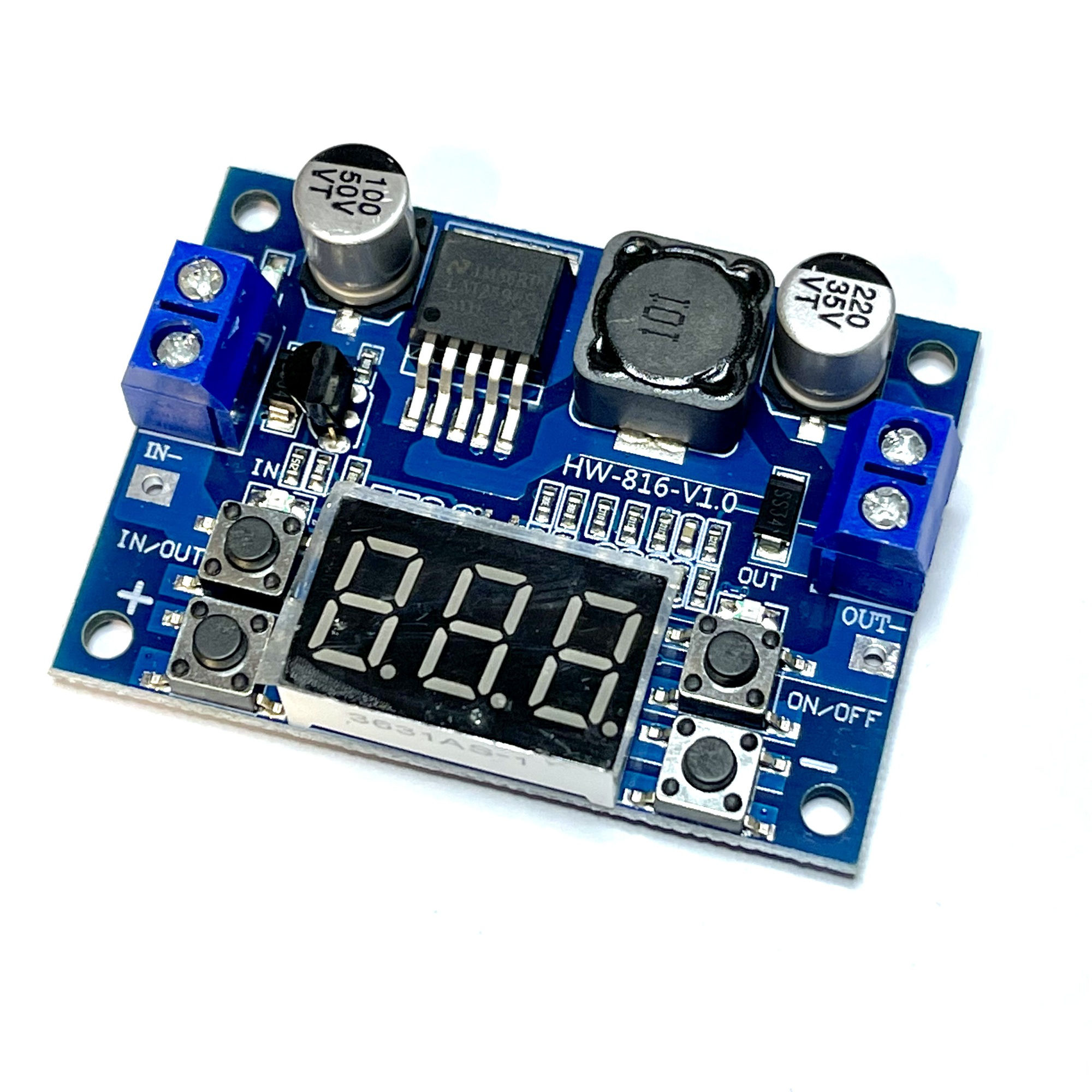
I also came across this fully programmable module with the LM2596. Naturally, the adjustable LM2596 is used for this. The setting can be made with push buttons and the 'shutdown capability' of the LM2596 is also used here so that the set output voltage can be switched on or off as desired. A small display with three 7-segment elements shows the voltage of the input or the output. Small push buttons make it possible to set any output voltage below the input voltage (between 7 and 36 volts).
Due to the adjustability and voltage reading, it is certainly an interesting module for the electronics workshop, but not really usable to build our Ultimate Multi Power Module. In addition, this would require four of these modules. The display of the current drawn and the option to limit or fuse it are also missing.
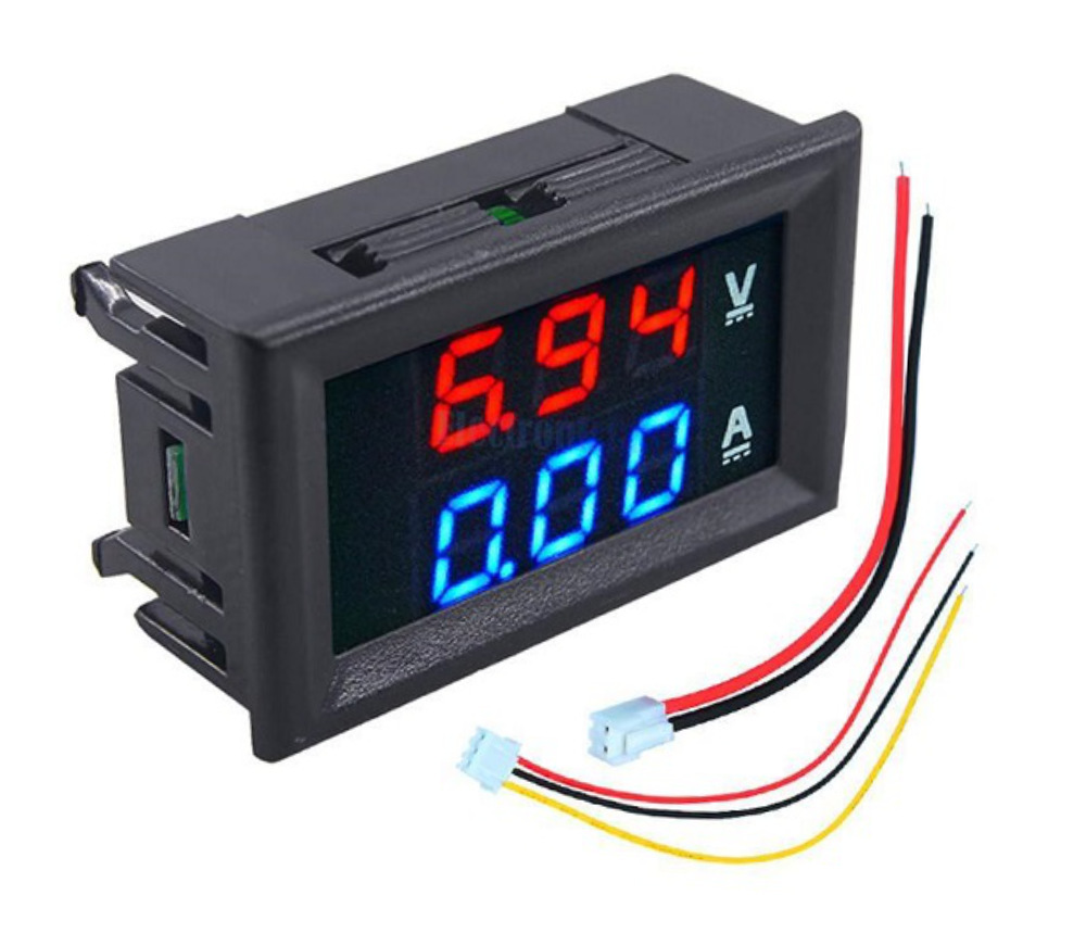
Obviously there are many more ready-made solutions for sale, but I have not been able to find a small module with which all wishes can be crossed off the list. We could make the often missing current readout ourselves with separately available voltage/current displays.
However, these modules are relatively large and not really ideal. The display is made up of only three 7-segment elements. The digital dot is fixed in a fixed position and the module is not auto-ranging. For those who mainly experiment in the area up to 1 Ampere, but who do want some space upwards, only the 10A model can be used. And this means that the reading is in 10mA increments.
The plan for the Ultimate Multi Power Module is moving towards a real DIY project that displays the voltages and the drawn currents on a small display such as the SSD1306 Display Module, which I also used in the Zauberling. Together with an Arduino Pro Mini, voltage regulators and a current sensor, it might be build with a PCB sandwich that fits in a Silberling housing.
Various sensors can be found for measuring the current and voltage. Some can be read over the I2C bus. Some sensors measure by means of Hall effect, others determine current by measuring resistance across a shunt resistor. The Hall effect measurement can generally handle larger currents, and the advantage of measurement over a shunt resistor is that it is quite precise for smaller currents.
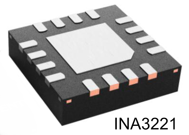
On ready-made sensor boards that work according to the latter principle, the INA219 is a widely used chip. Because we eventually will design a custom printed circuit board for this project, it will not be a problem to eventually use several INA219s in the Ultimate Multi Power Module. However, it could be easier with a variant of this chip that can measure three individual channels: The INA3221 is a module with three INA219s in one.
I would of course like to measure all four voltages, but perhaps this is a good option to monitor the three most important voltages. The 3.3 volt is the least important and it's in practice only used for powering possible external sensors. If we can't read the 3.3 volt but have a good view of the three main buses, then we can live with that.
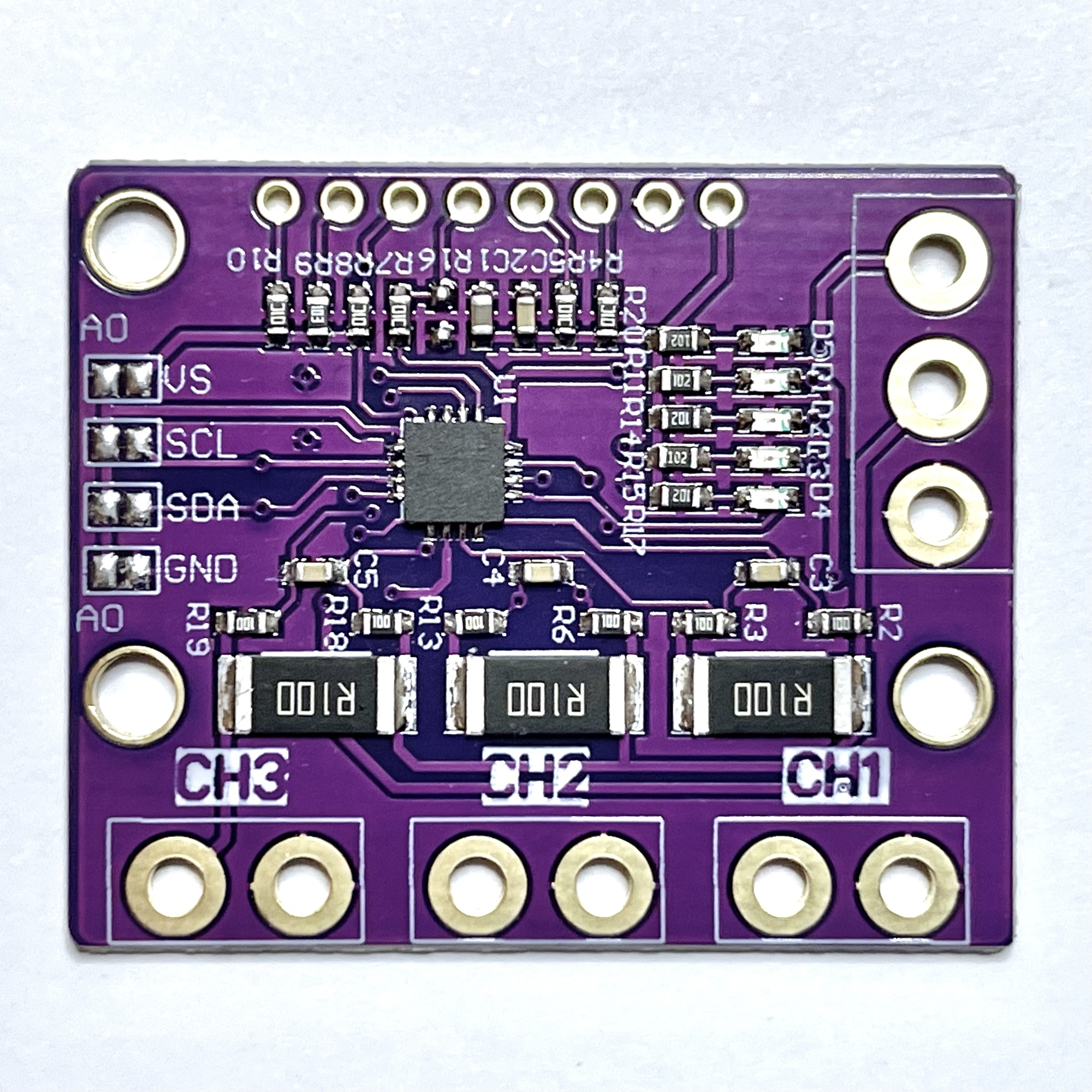
Sensor boards with the INA3221 appear to be easily available. However, the board I bought turned out not to be usable for measuring three independent voltages and currents. One side of the buses has been connected to the PCB and connected to the minus (ground), so that the module cannot make three individual measurements. And for the Ultimate Multi Power Module, that's exactly what we want. Fortunately, you can already find online how to fix the board by disconnecting the jumpers and soldering a few wires yourself. Corrected boards are now also for sale.
The ready-made sensor board is relatively large and equipped with various unused connections and indication LEDs. However, after some adjustments, it is perfectly usable for the first build-up of the prototype of the module. Ultimately, a custom printed circuit board will be designed which only the most necessary stuff around the INA3221.
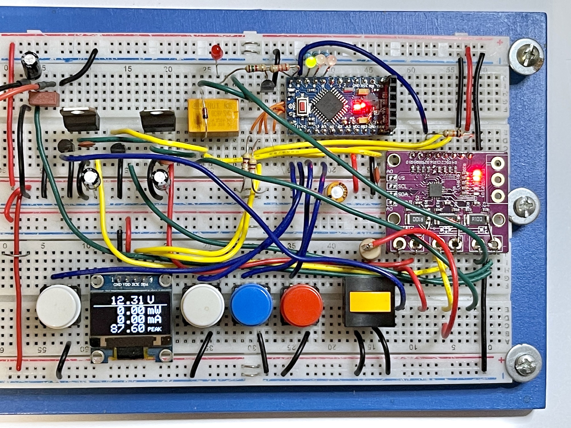
The sensor board has now been put on a breadboard together with the Arduino Pro Mini. The four voltages are made by voltage regulators. The display is also connected and a setup has already been made with the software of the module. The measurements with the current sensor over I2C and the display of the measured values on the display have now been realized.
The white push buttons cycle through the different display modes of the screen. With the blue button the measured current peak value can be reset. The red button is reserved for setting the maximum current above which the automatic fuse should trip. Pressing the orange button connects a 100Ω load resistor to any voltage output to force a current increase. All measured power, voltages and currents are visible on the display in real time.
Some wishes of the list still have to be realized. But the relay for the further development of the automatic fuse has already found a place on the breadboard. In the next part we will discuss the circuit diagram as it begins to take shape and further perfect the software.