
Some time ago I thought along with a fischertechnik club member about a model in which a figure-eight motion had to be described. The challenge was to have an element, such as a cart or ball, describe a path according to a 'bow shape' or 'lemniscate' curve. This produces a movement that intersects itself at the center. How's that for a challenge?
In researching the mysterious lemniscate, I came across some interesting facts. Then I tried out some methods and built a motor controller for the occasion to be able to regulate the speed of the motor.
The term “lemniscate” is derived from the Greek word for hanging cord or garland. As a geometric figure, this shape has a long history and acquired not only mathematical, but also symbolic meaning. For example, the shape is a model for the symbol for infinity (∞) in mathematics and is used as a symbol of eternal life and the interaction of opposing forces. In the tarot card game, a figure balances two pentacle coins or talismans in a lemniscate to represent infinity and eternity. The lemniscate also occurs indirectly in nature: Whoever puts a stick in the ground and marks the top of the shadow that the sun makes on the ground every day for a year at the same time, will eventually also see this figure eight appear.


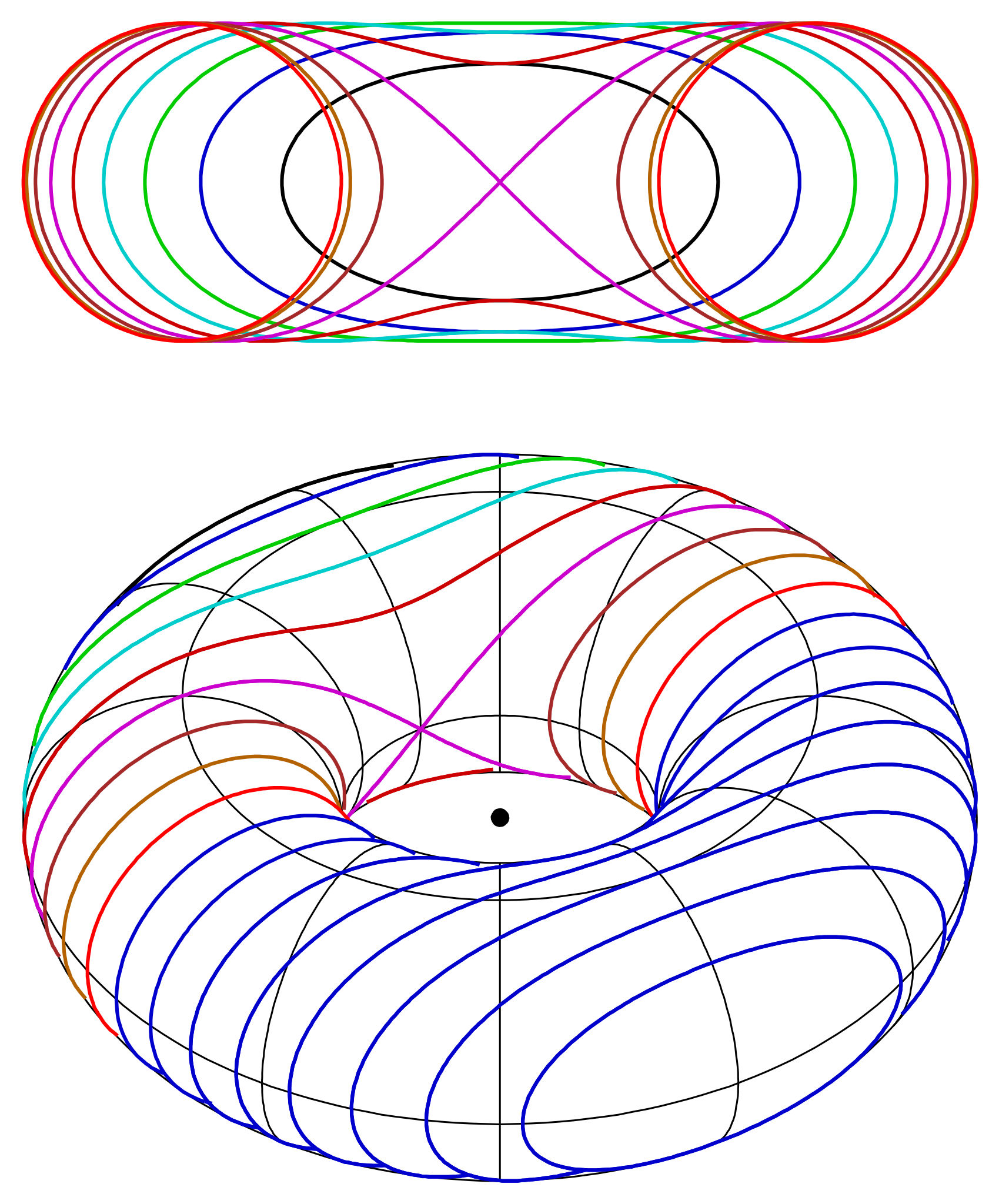
The mathematical relevance of figure-eight curves seems to have been first recognized by Proclus, a Greek Neoplatonist philosopher and mathematician who lived in the 5th century AD. Proclus considered the cross-sections of a torus through a plane parallel to the axis of the torus. As he noted, the cross-section for most such sections consists of one or two ovals; however, when the plane is tangent to the inner surface of the torus, the cross-section takes on a figure-eight shape. This shape reminded him of the shackles with which two feet of a horse can be held together during transport. Proclus therefore called the shape the “horse buoy” or “hippopede” (Greek: ἱπποπέδη). The name Booth's lemniscate for this curve dates back to the study by the 19th century mathematician James Booth (1810 -1878).
If you do further research into this form yourself, you will soon discover that there are different variants. Such as Bernoulli's lemniscate (Greek: λημνίσκος, band) proposed by Jakob Bernoulli in an article in his Acta Eruditorum (1694). Or Gerono's lemniscate. A variant more flattened at the sides by the French mathematician Camille-Christophe Gerono (1799-1891).
A Booth hippopede is symmetrical with respect to both the x-axis and the y-axis, and can be mathematically described as:
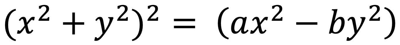
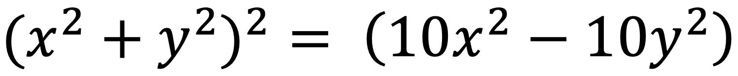
where the factors a>0 and b>0. As these factors are chosen further apart, the lemniscate will consist of increasingly purer circles instead of stretched ellipses. This can be visualized beautifully in the handy online visualization tool GeoGebra. For the red curve the same factors as global scale factor are used and the formula:
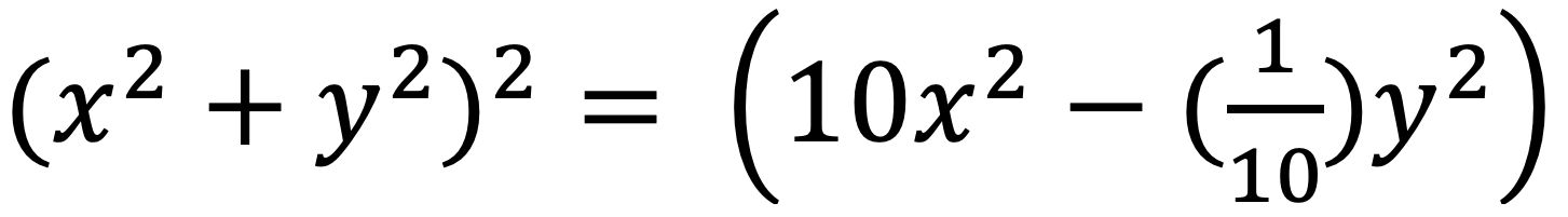
while for the green curve the factors have been chosen inversely proportionally:
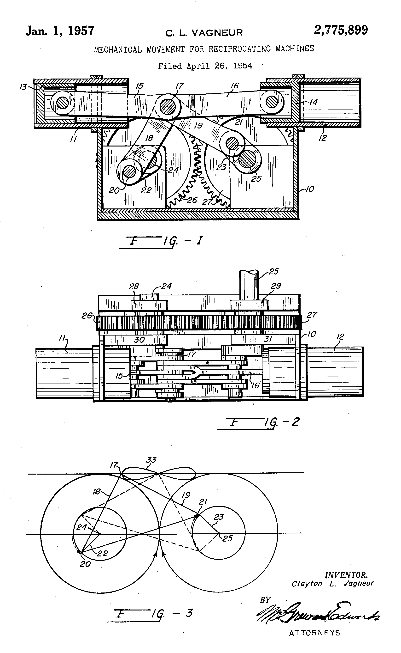
A logical first step seemed to be to mechanically describe the purest possible lemniscate shape with a fischertechnik model. Inspired by an article about Jansen's 'Strandbeesten', I looked for a variant on the 'leg mechanism' with which the figure-eight could be made by means of rods and transmissions. Some construction experiments and an online search eventually led to an interesting story about an inventor who found out in the 1990s that his idea had already been patented in 1957 by one Clayton L. Vagneur. The entire description of this patent is available online.
Vagneur was not looking for a method of reproducing the lemniscate curve mechanically. He wanted a transmission that exerted as little lateral pressure on a piston as possible. With his patent he filed a general method for converting a rotation into a reciprocal (sliding) movement for use in combustion engines and pumps. In his original sketch, however, the lemniscate shape (curve no. 33) immediately catches the eye.
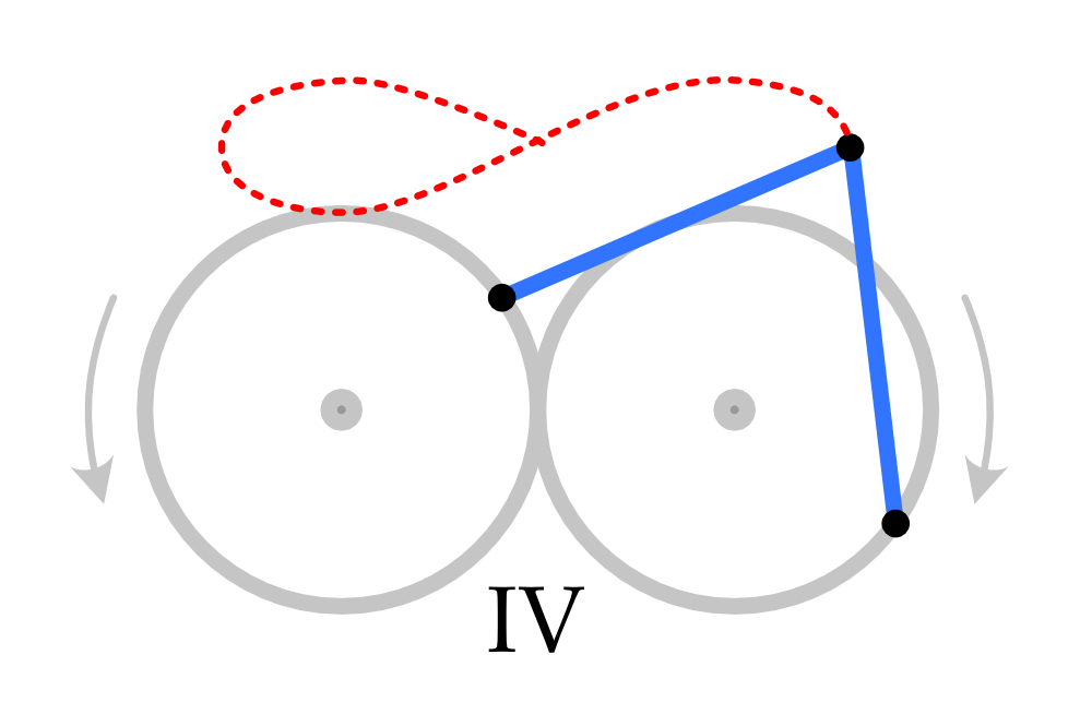
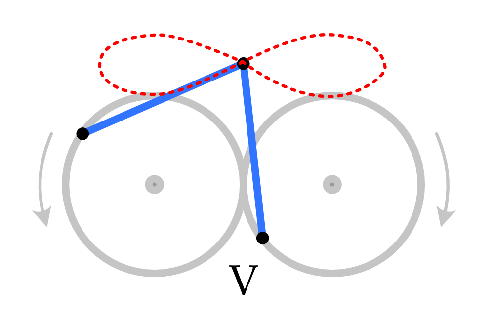
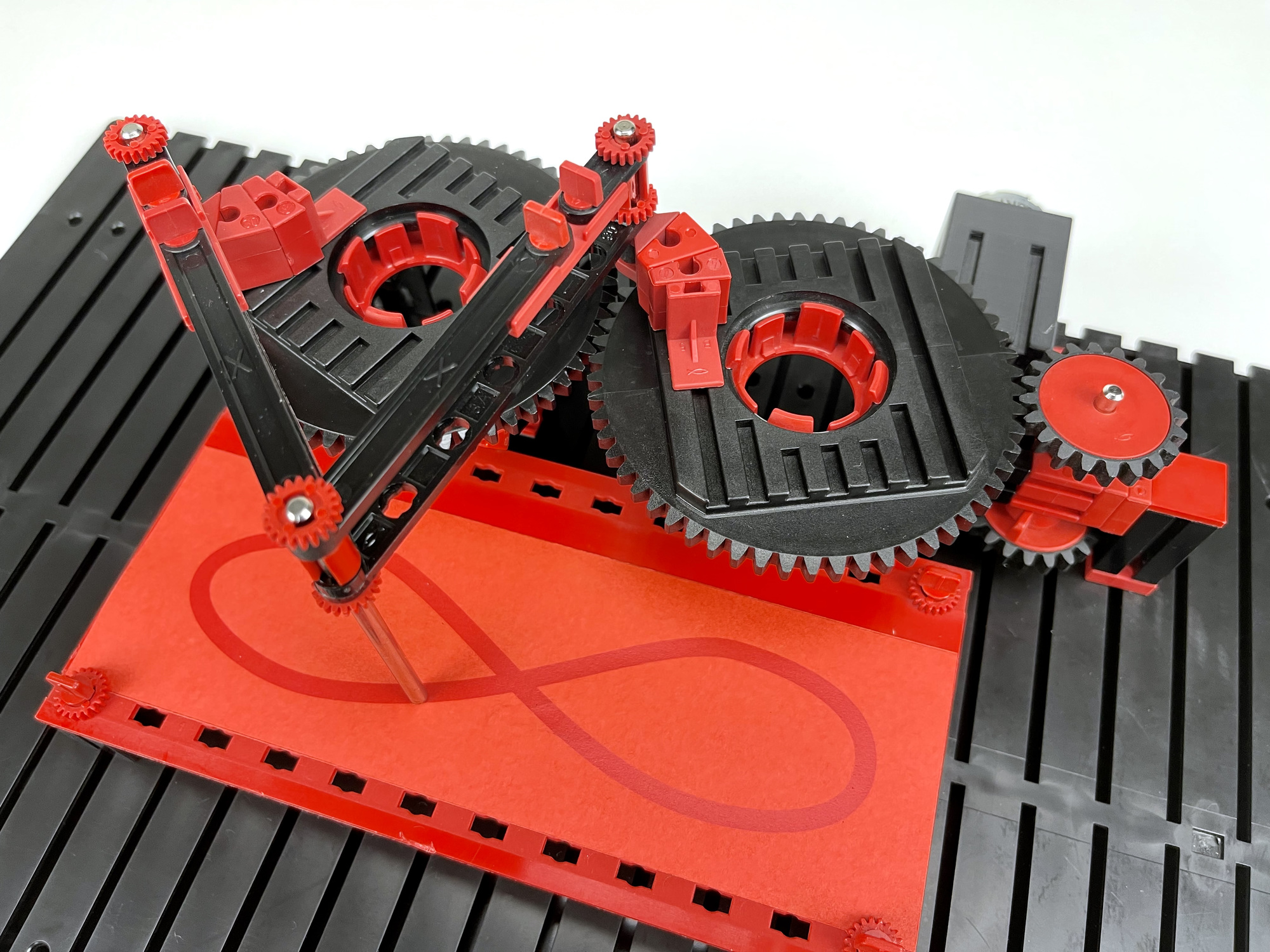
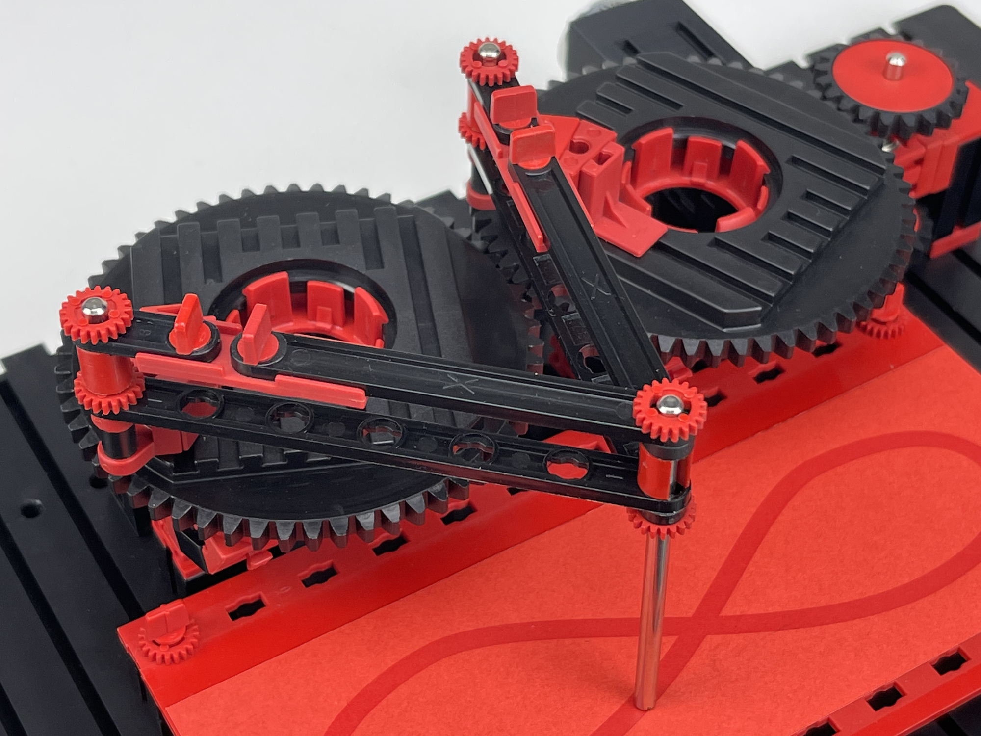
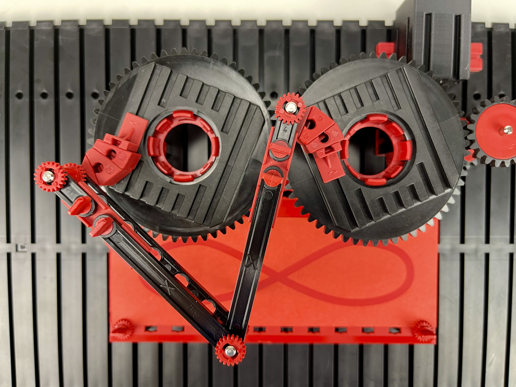
The basis of this mechanism is formed by two connecting rods connected in a pivot point on the edge of two mutually synchronized wheels. The wheels have an opposite direction of rotation and are a quarter turn (90 degrees) out of phase with each other. A few stages of a complete revolution of these drive wheels are shown in the figure. The pivot point of the connecting rods goes through a hippopede curve. This is greatest by placing the pivot points as much as possible on the outer edges of fischertechnik slewing rings (31390 / 31391).
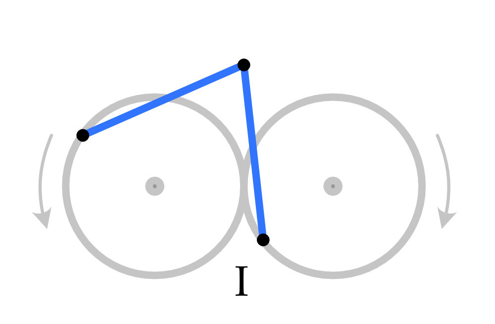
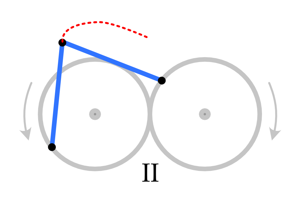
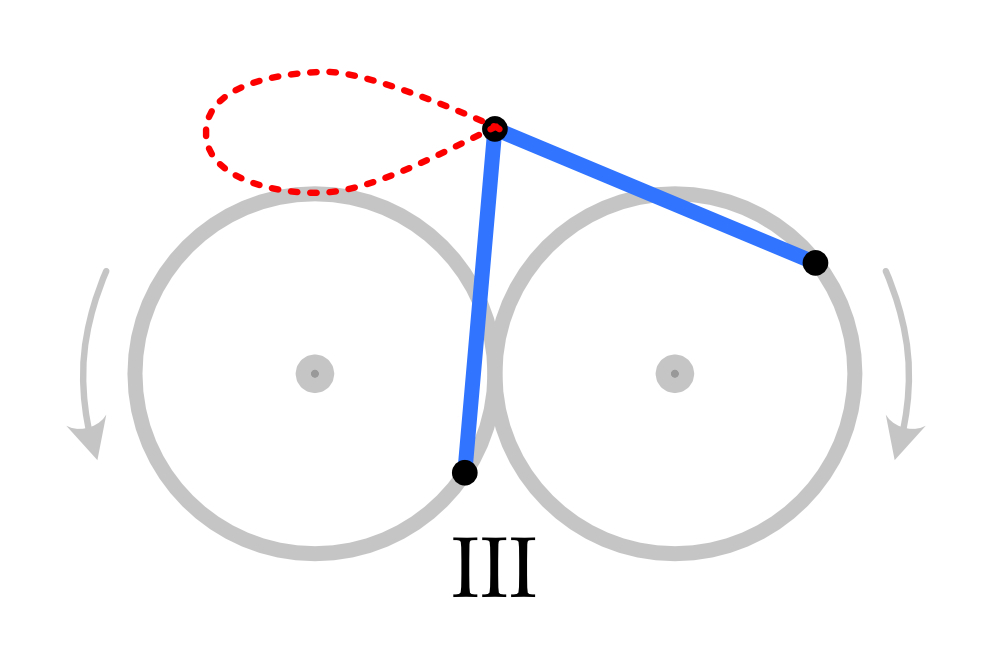
In this way it seems possible to have a lemniscate shape described with an old American patent. However, the path of this movement is not yet directed along the curve. As a basis for a model in which a mounted element (for example a fischertechnik figure) has to move along the path, this solution does not yet seem optimal.
Because the desired path intersects itself, a construction with a permanently mounted element at the intersection of the curve seems to present a mechanical problem. A possible alternative is of course not to mount the element at all, but only to give it the desired movement. For example, it must be possible to make a cart or ball roll around in a moving track. This also opens up the possibility, if necessary for the propulsion, to 'transfer' the moving element at the intersection and thus to mechanically avoid the intersecting node completely. For the construction of such a moving track, the flexible fischertechnik ball tracks seem to offer more possibilities than the curved statica elements with a fixed radius.
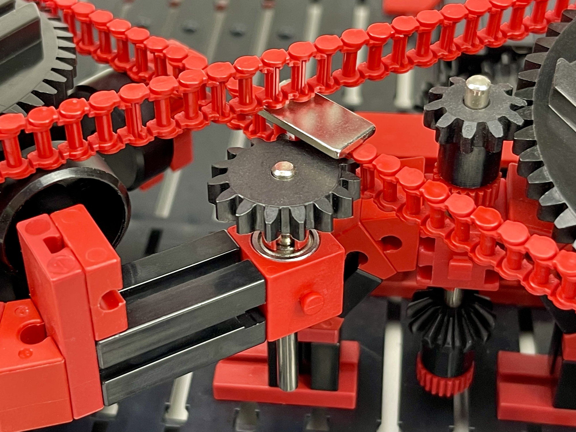
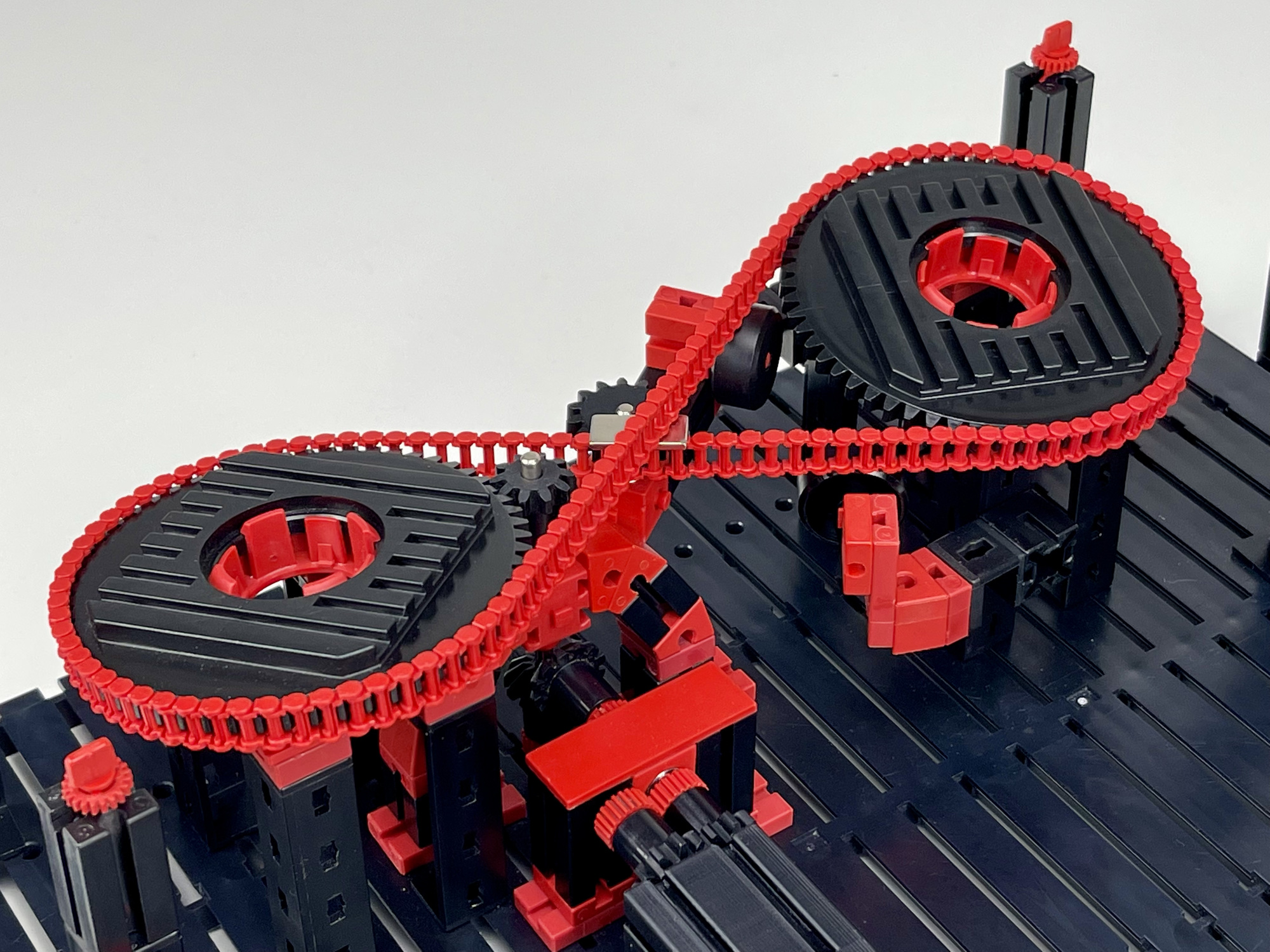
Before venturing into some sort of mechanical "transfer" system of the moving element at the center, I first tried to approximate Booth's hippopede (red curve in the graph above) with a chain mechanism. A magnet on a chain describes the figure of eight. The critical point in this solution remains the intersection of the figure, and in this case the chains. In order for the flat magnet to pass, even a few guide rollers had to be placed.
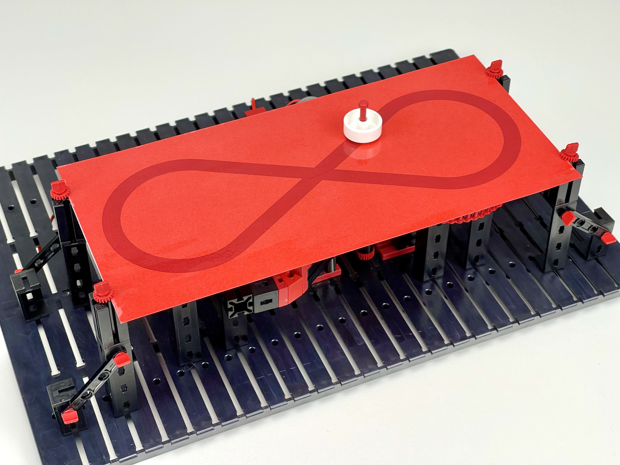
By turning the pivot axes of the two sprocket wheels 15 degrees relative to each other, the chain could be routed. A neodymium magnet, glued to the side of one chain link, can make the other magnet in the pedestal move in an almost perfect lemniscate movement on the Plexiglas plate.
In the previous models, a fairly accurate Booth hippopede is described with equal factors a and b in the aforementioned formula (red curve). And in the second model, the movement is also quite nicely directed along the curve due to the friction. A more accurate trajectory description could be enforced with a second magnet on the chain, but even then the weight of the circulating element is very limited by the use of permanent magnets. Even the powerful nedymium magnets span the maximum distance in the intersection of the chains with difficulty.
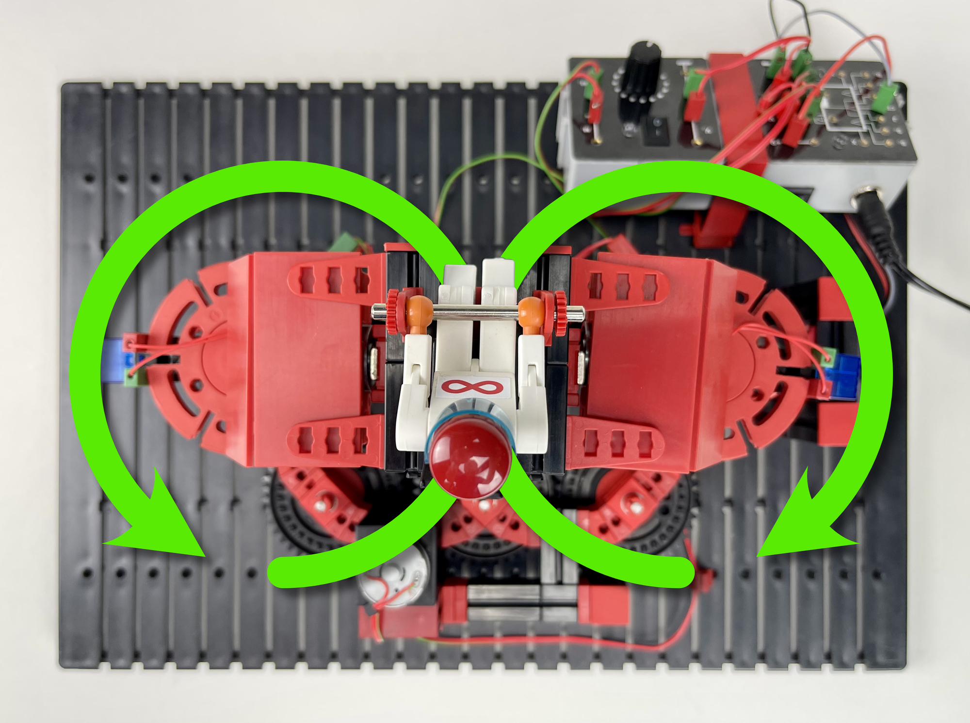
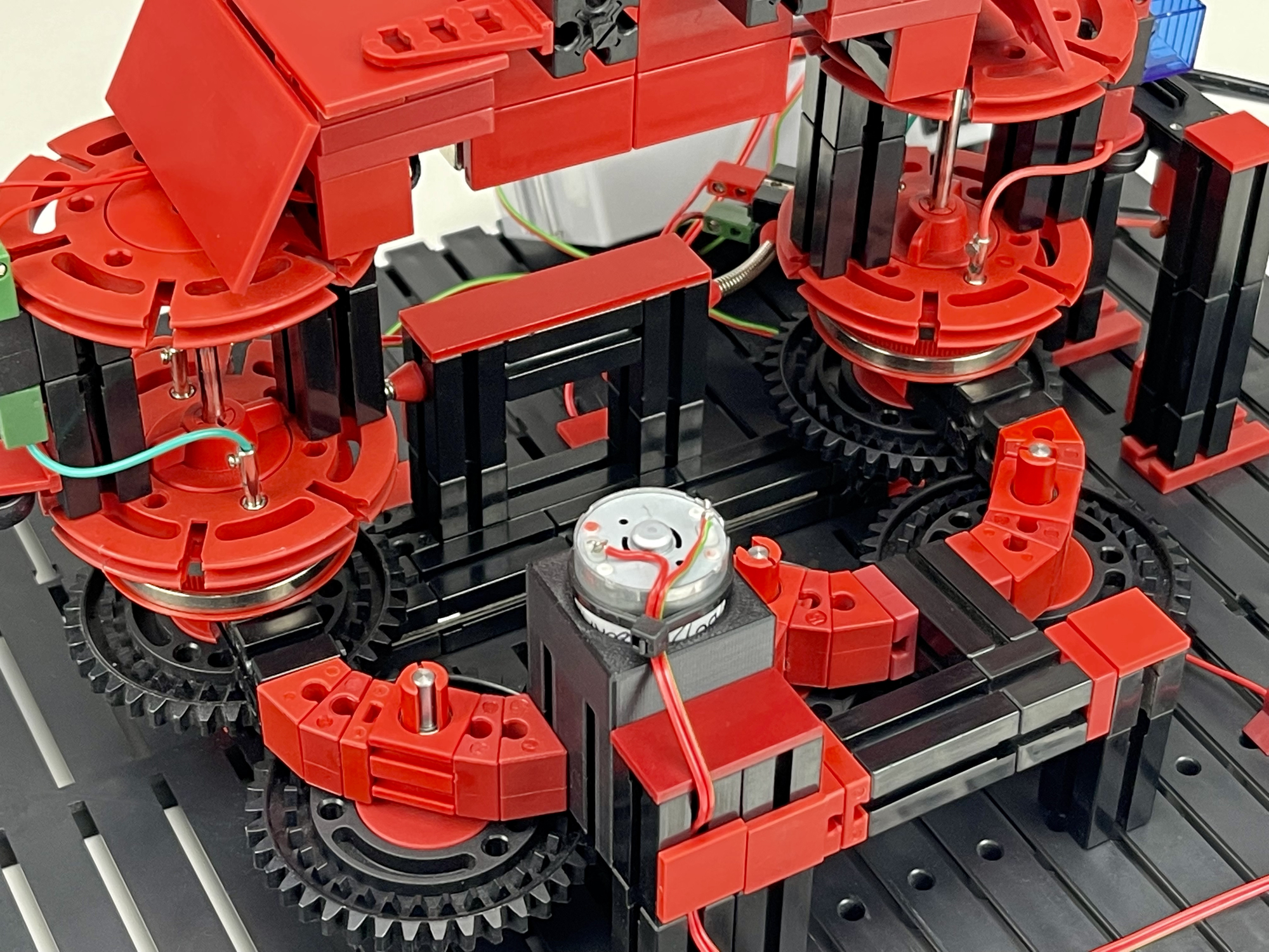
That is why I then looked for a construction with two wheels rotating against each other, which each time took over the moving element in the center from each other. In this way I approached Booth's green-drawn hippopede in which factors a and b are inversely proportional.
After some puzzling with a mechanical solution (which must be there) I returned to the principle of magnetism. Only in this case, and also because its operation must be controllable, with electromagnets. The fischertechnik magnet 142504, or a Chinese equivalent such as the "ZYE1-P20/15" can be used for this.
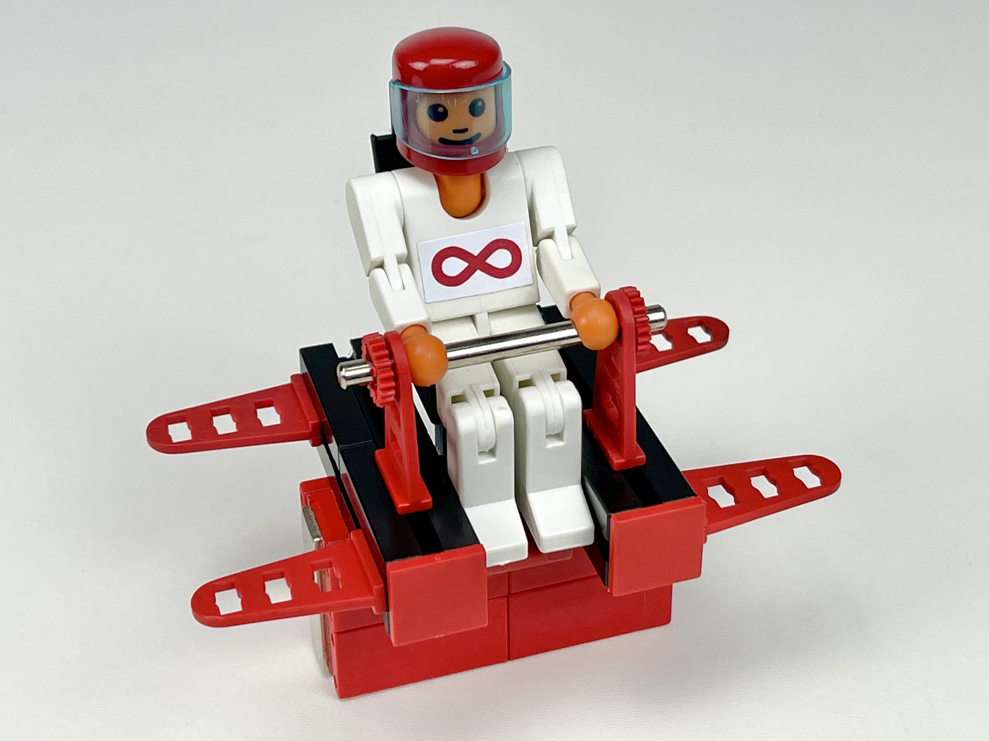
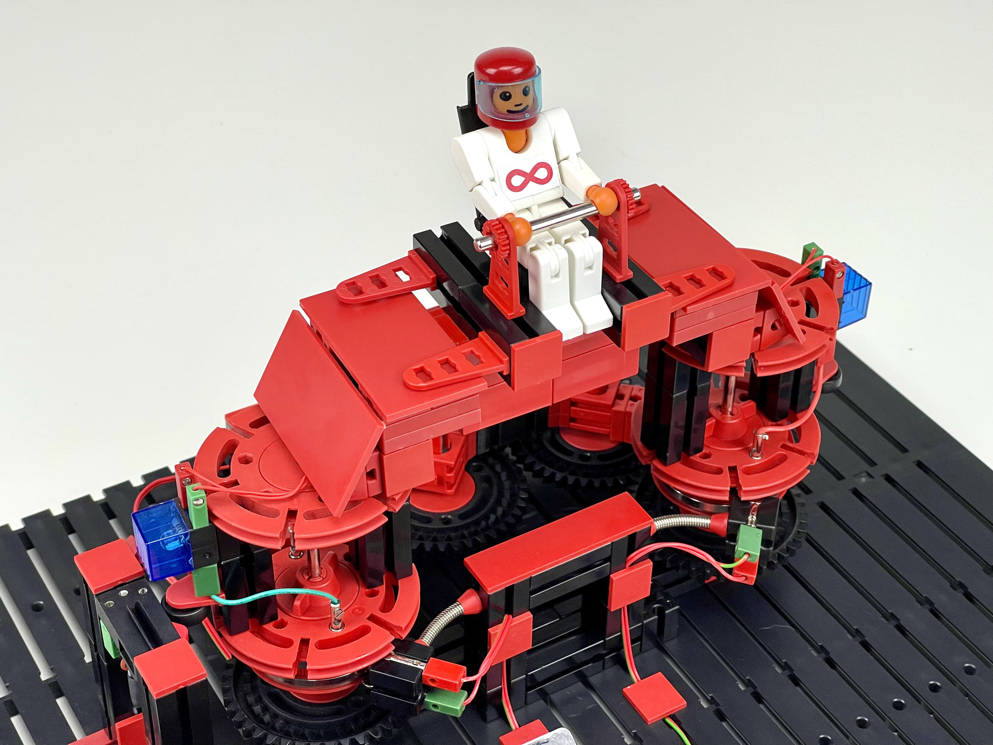
This led to the following construction that allows Lorentz Lemniscaat to spin his circles ad infinitum. Stuntman Lorentz, whose name in this context is of course a nod to the power on which he so relies, is always attached to one of the electromagnets of the transport wheels. Returning to the center, he is automatically taken over by the other wheel. A pulse switch on a flip-flop takes care of the switching. Because there was quite a bit of experimentation with the rotational speed and position of the pulse switch for the flip-flop in the beginning, Lorentz's request for a crash helmet was granted early in the process. And I assure you that no fischertechnik figures were injured in the creation of this model. 😆
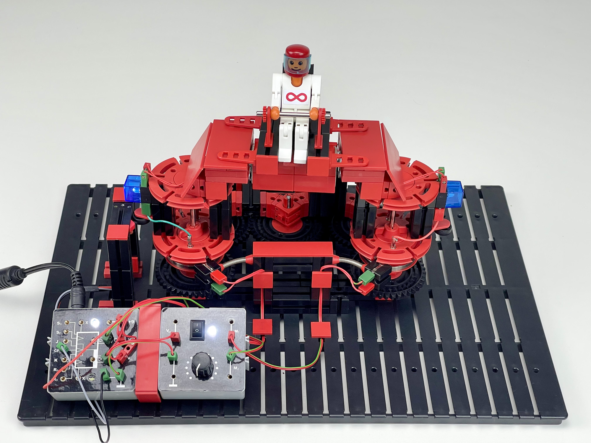

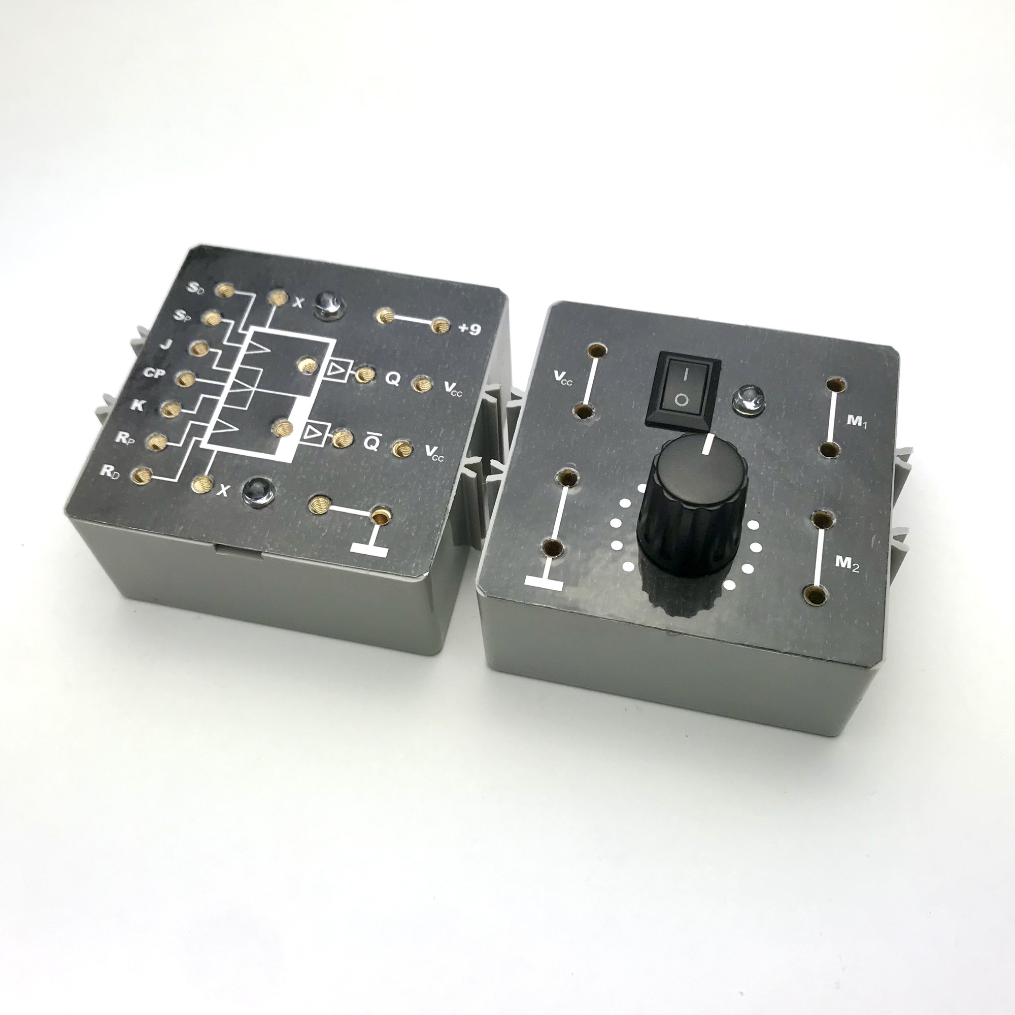
This method required a flip-flop with both outputs directly capable of alternately driving an electromagnet. For the occasion I built a flip-flop for this, which I provided with driver outputs, each with an IRF520 Power MOSFET, so that no additional relays (with the necessary wear, noise and delay) were needed. To make it easier to experiment with the speed I also built a motor controller for the used JGA25-370 400rpm 12 volt motor. A simple scheme with PWM control was sufficient for this. Both modules were housed in gray fischertechnik cassettes (35359) and fed from a 12 volt mains adapter. The faceplates were printed on plain paper on a laser printer and then laminated and cut.
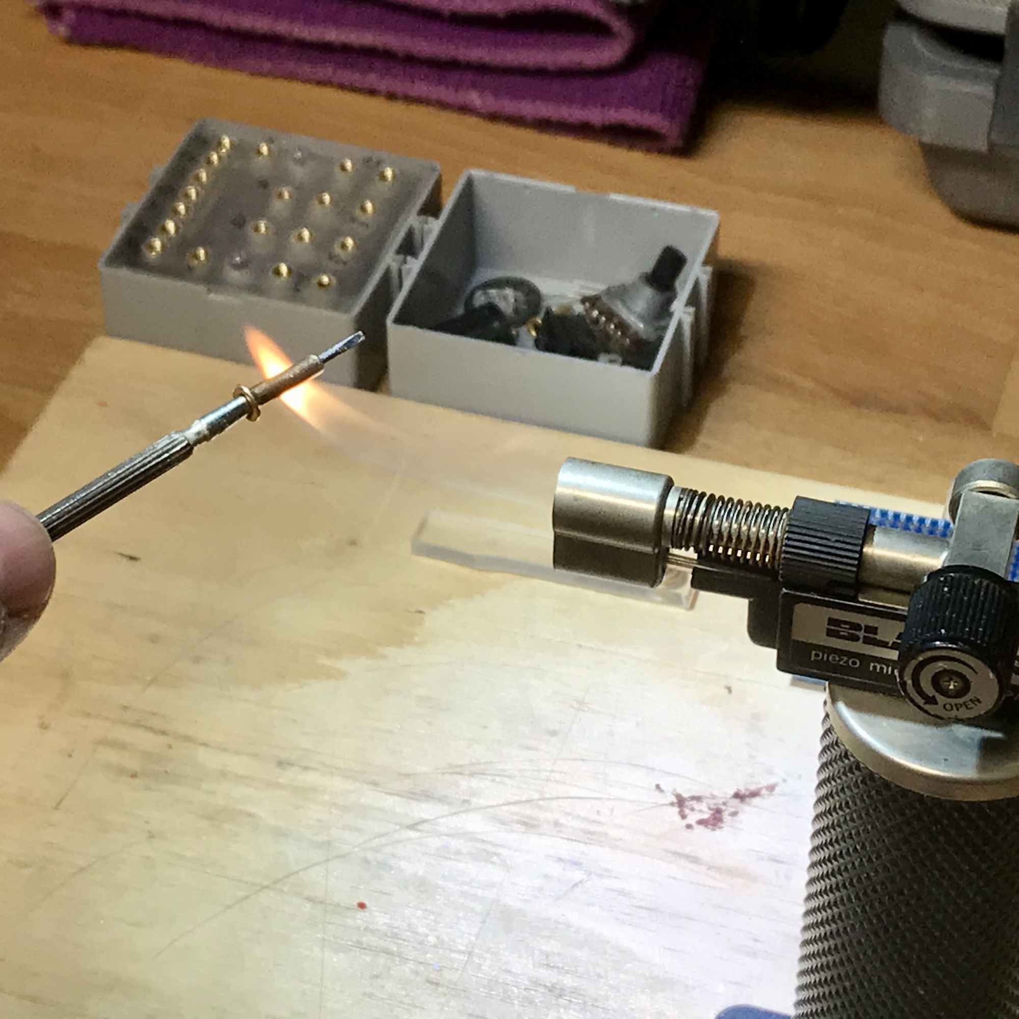
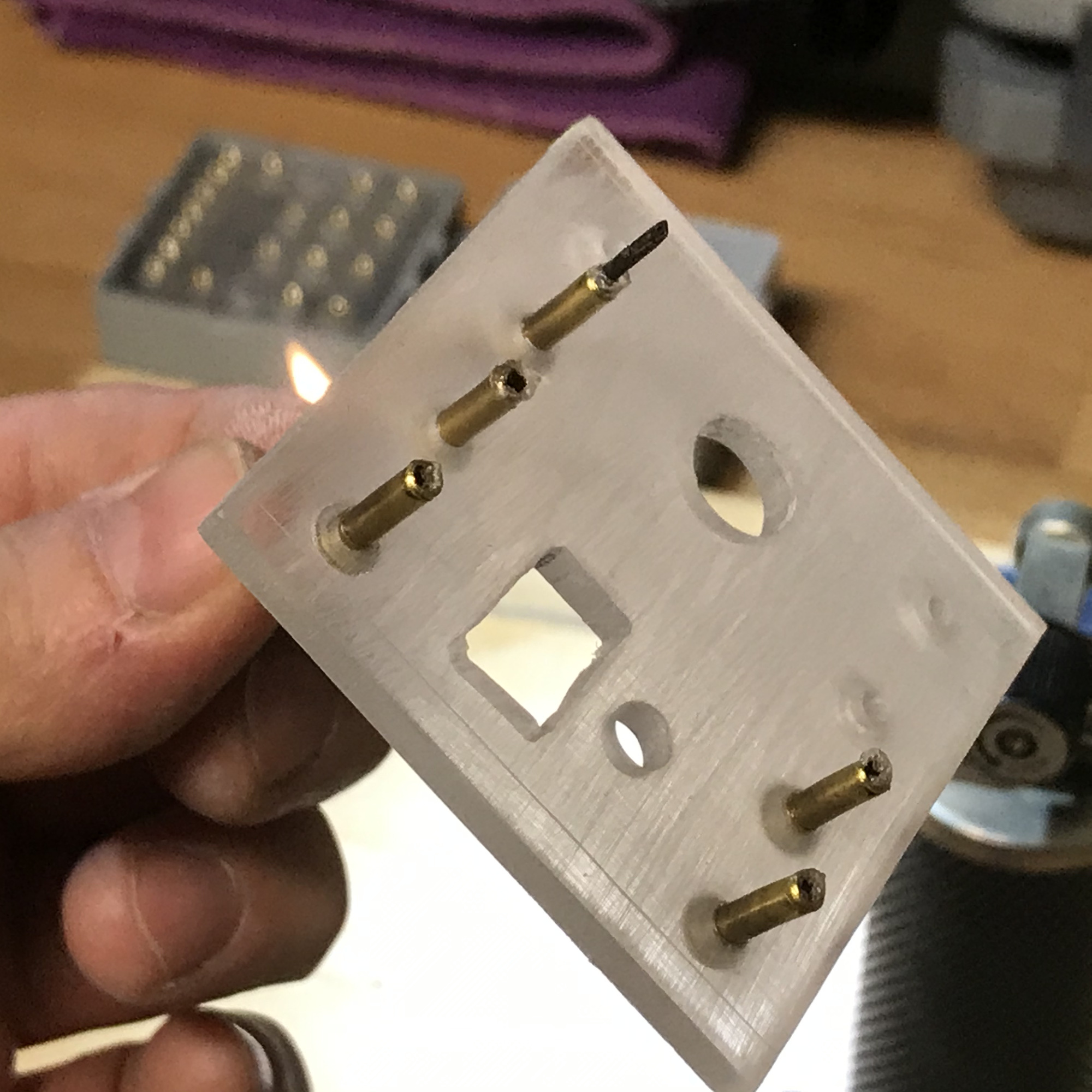
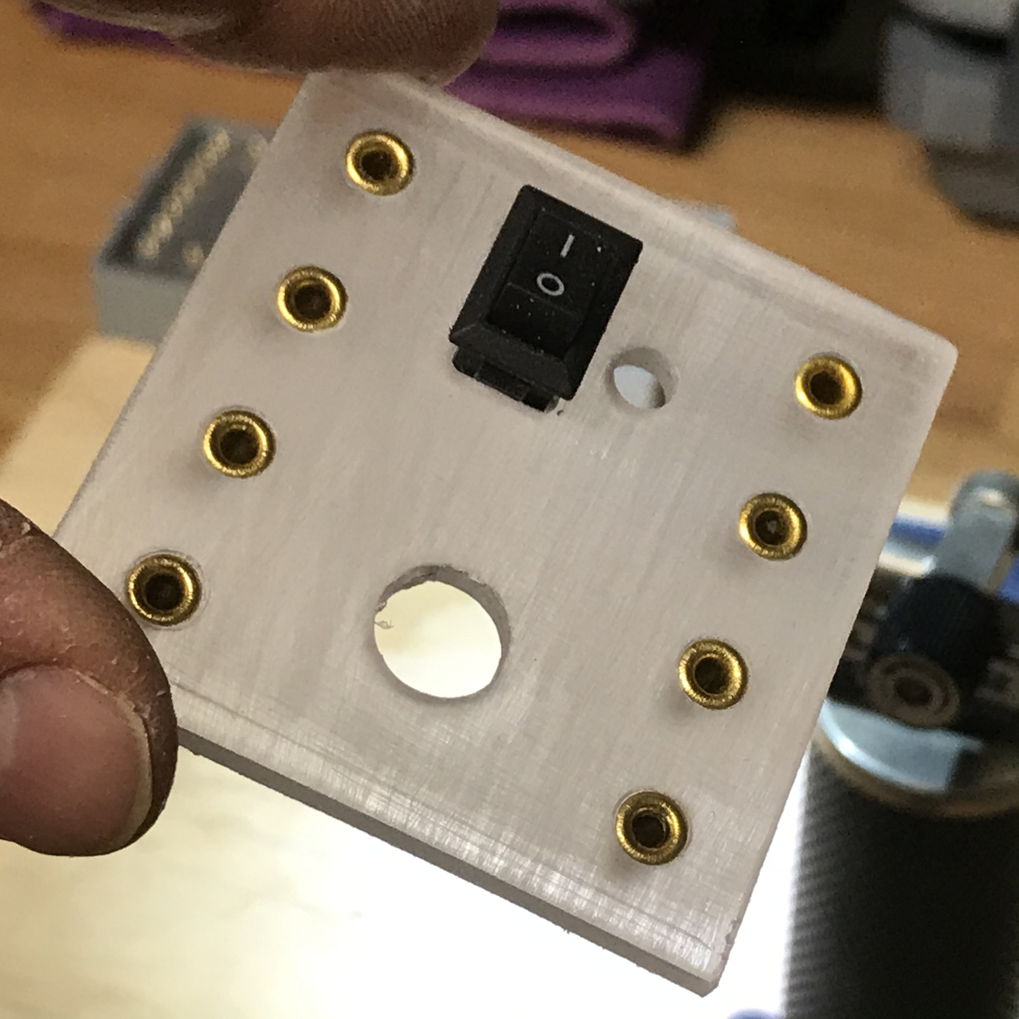
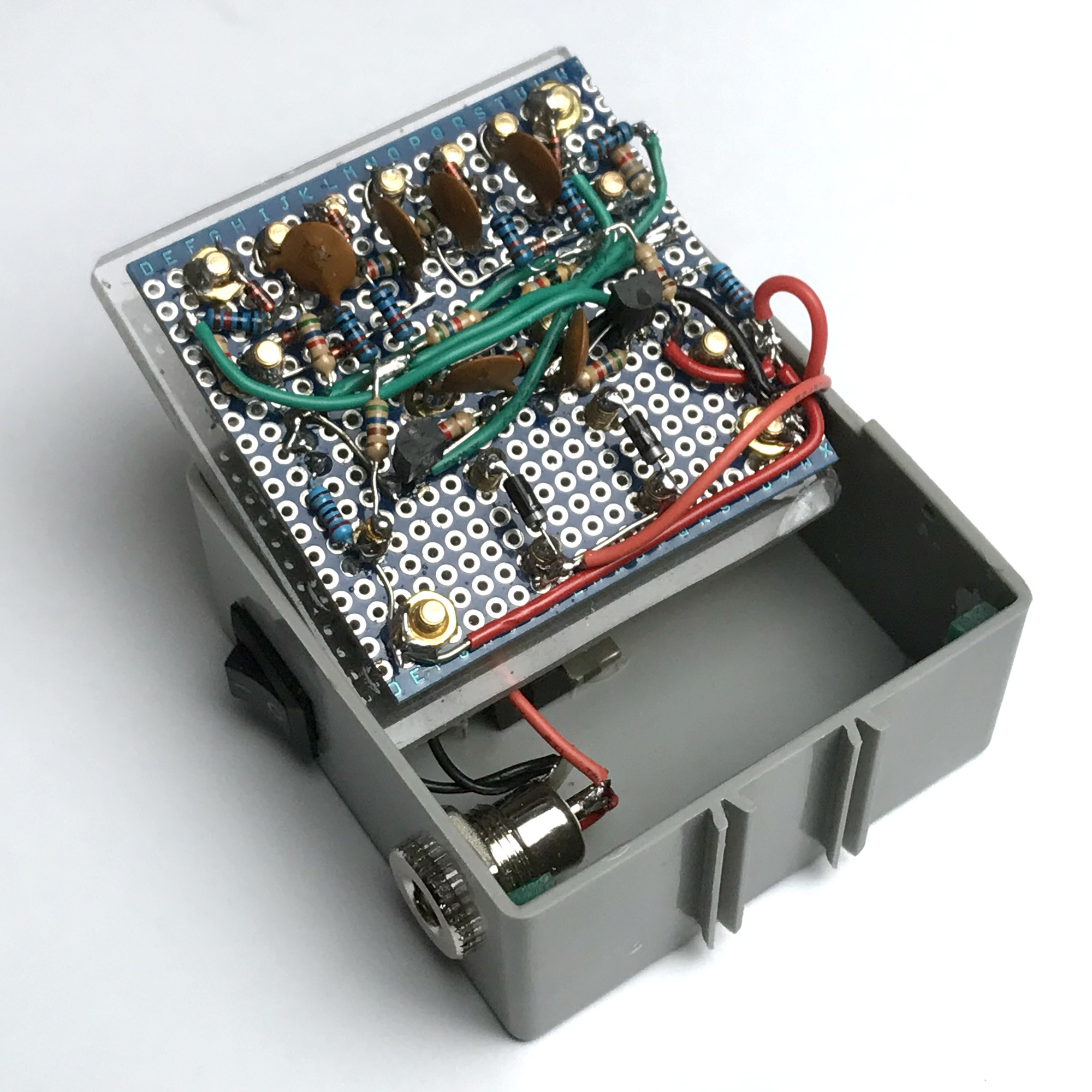
Because I preferred to have the attachment (and the forces of the plugs) of the plug connections directly on the cover, this tinkering was also an investigation into alternatives to the well-known 'bundhülsen' that are normally soldered on the printed circuit board itself. In addition to copper M3 spacers (search online for 'Hex Nut Spacing Screw Brass'), hollow rivets (search online for 'Copper Hollow Tubular Rivets 3mm') also prove to be very suitable for this. After heating, the latter can easily be pushed into a slightly too small hole drilled in the Plexiglas front, or PLA plastic, of a 3D-printed lid. After cooling, the tubes are firmly anchored. If necessary, the tubes can be re-drilled at the front with a 2.5 mm drill for a perfect fit for the fischertechnik plugs.
Perhaps my tinkering will inspire others to experiment further and construct paths of motion that come even closer to the mathematical lemniscate. Like with the toy shown in the movie in which a ball is sent around? Or maybe it is possible with an additional rod construction to steer the direction of the element along the path along with the curve with the first solution?
Or maybe make a completely mechanical construction? That should be possible according to this video, and this video, right? In short, there is still plenty to work out and tinker with. But even if you just smile the next time you see this wondrous shape, Lorentz Lemnicate has already achieved his goal. The lemniscate shape will surely amaze people until the ∞...
This article on endless lemniscate was also published (in the German language) in issue 2021-2 of the ft:pedia; a very interesting online magazine about technology in combination with the construction material fischertechnik.