If we zoom in far enough on the integrated circuits in modern computer systems, we see that they are constructed from a handful of basic digital functions. All more complex functionality is constructed by intelligently connecting multiple these basic functional building blocks.
The seven basic gates in digital technology are AND, OR, XOR, NOT, NAND, NOR, and XNOR. These are electronic components that produce a single binary 'active' (1) or ‘inactive’ (0) output signal based on the pattern of logical zeros or ones at their binary inputs. They form the building blocks for all more complex digital circuits.
The basis is formed by three logic gates:
In addition, for binary arithmetic operations, among other things, it proved useful to supplement these with a logical function that is very similar to the OR gate but still differs:
In Boolean algebra, which can be practiced with the gates, it is sometimes more practical to have gates whose output signal is inverted. In other words, an extra NOT gate is already built into the output:
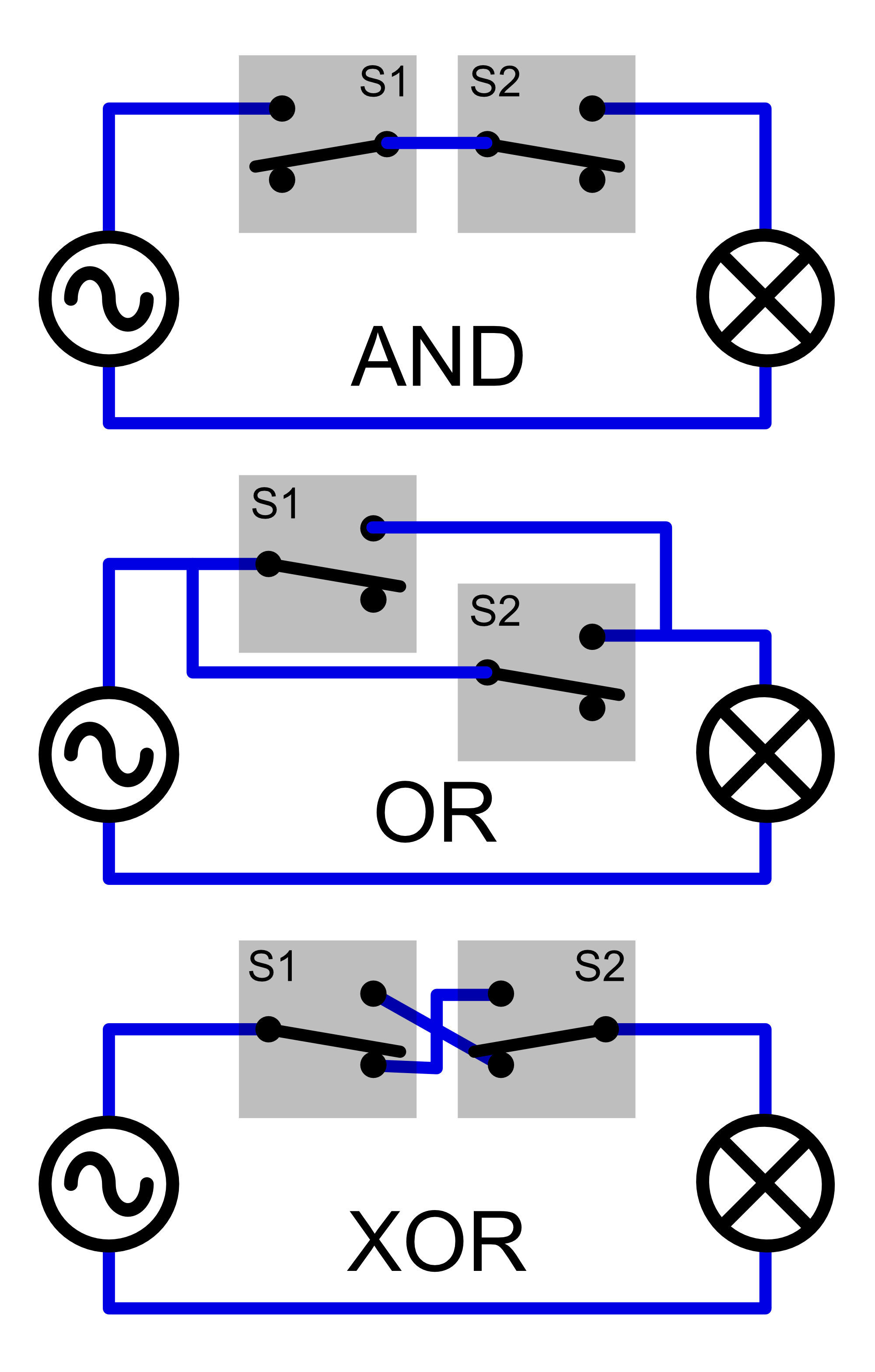
These logical functions form the basis of all digital systems. When implemented electronically, they enable everything from simple calculators to complex computers. But the functionality of these basic functions is also reflected in circuit diagrams with relay contacts or simple switches, as shown in the image below. If we connect a lamp with two switches in series, an AND function is created. After all, both switches must be closed before the lamp lights up. If we connect the switches in parallel, the lamp will be controlled according to an OR function. We are all familiar with the XOR function too: just think of the two switches that allow us to control a single light in a stairwell.
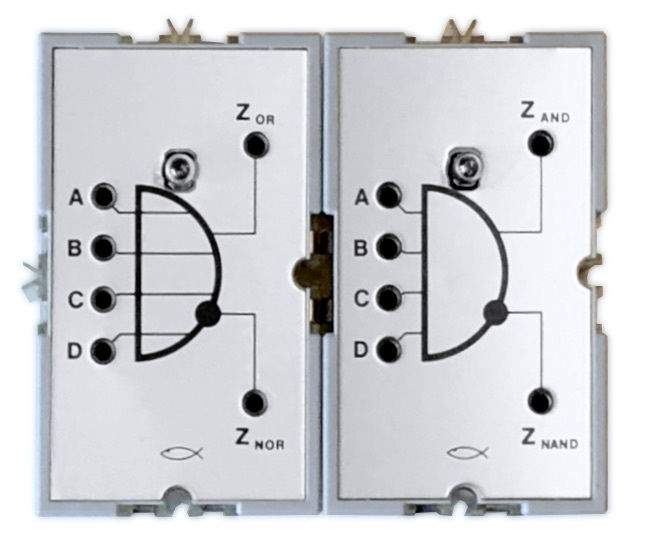
In my experiments, I often work with the classic fischertechnik electronics modules from the 1970s. Fischertechnik once released an AND/NAND and an OR/NOR module (the modules in the photo above). Both modules have four inputs and work with negative logic. This means that the supply voltage level is ‘inactive’ (0) and as soon as it drops to zero, it is interpreted as ‘active’ (1). A practical feature of these modules is that the AND is also a NAND, and the OR can also be used as a NOR because both the normal and the inverted (NOT) output are available. This meant that there was never any need for a separate NOT gate module. After all, by applying Morgan's laws, the desired digital function can always be obtained, even if the complementary input signals would actually be preferred.
The vintage fischertechnik electronics modules are sometimes affectionately referred to as “Silberlingen” ('silverlings') because of their shiny front plates. However, fischertechnik never produced an XOR module. Perhaps the XOR function was considered too niche and too eccentric, which is why it never made it onto a “Silberling” module.
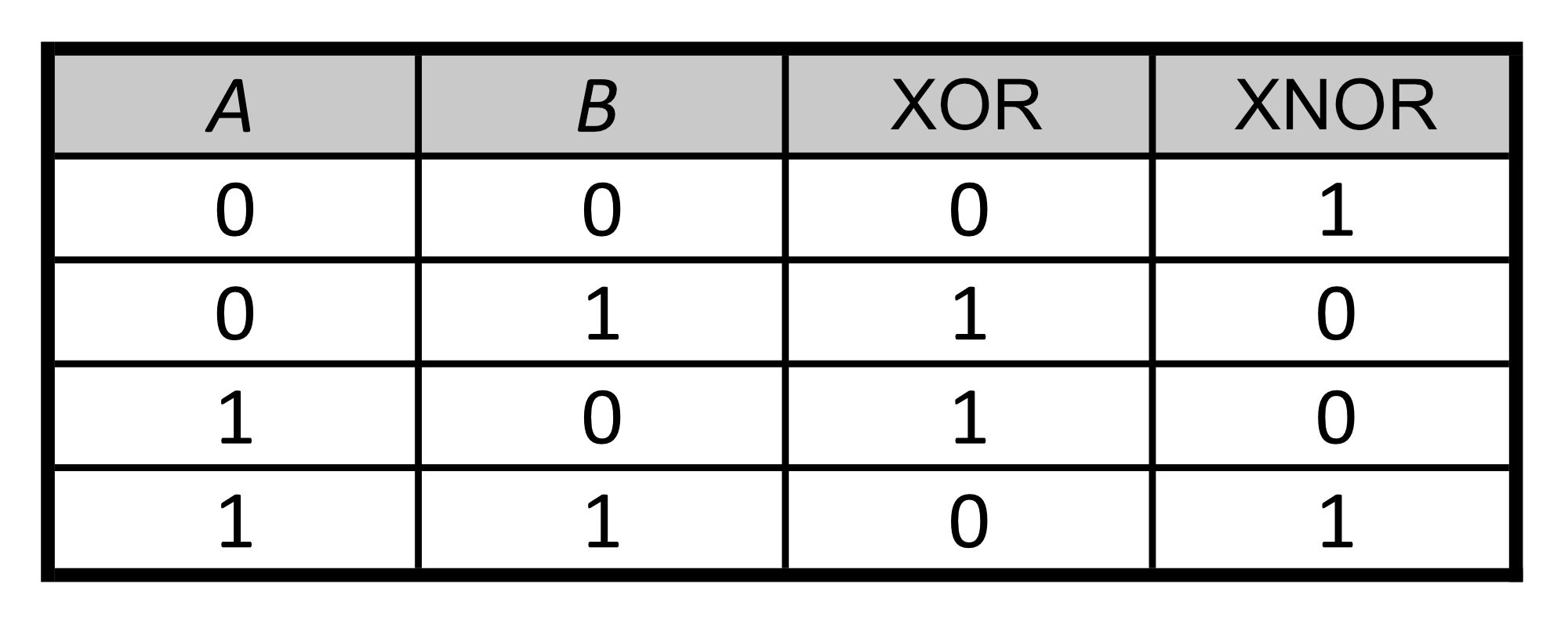
More generally, we can conclude that in the field of process automation, the XOR function is useful for detecting the possible difference between two signals. For example, to trigger an alarm when a sensor detects a deviation from the configured setting. See the (truth) table on the left to see how the output behaves with different combinations of the two input signals.
In digital technology, the XOR function, performed both electronically and in software, is used more frequently and has various applications. A few examples:
On the right is one of the ways in which the XOR functionality can be constructed from other logic gates. A NAND (or an AND followed by a NOT/inverter), an OR, and an AND gate are used, but there are other possibilities. A common configuration is built from four NAND gates. In the absence of an XOR ‘Silberling’, we can also build the XOR function from these three ‘vintage’ fischertechnik modules, as shown below.

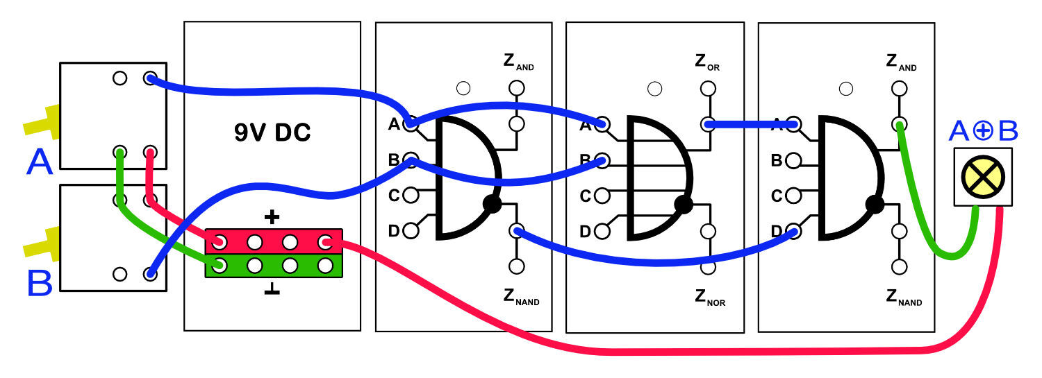
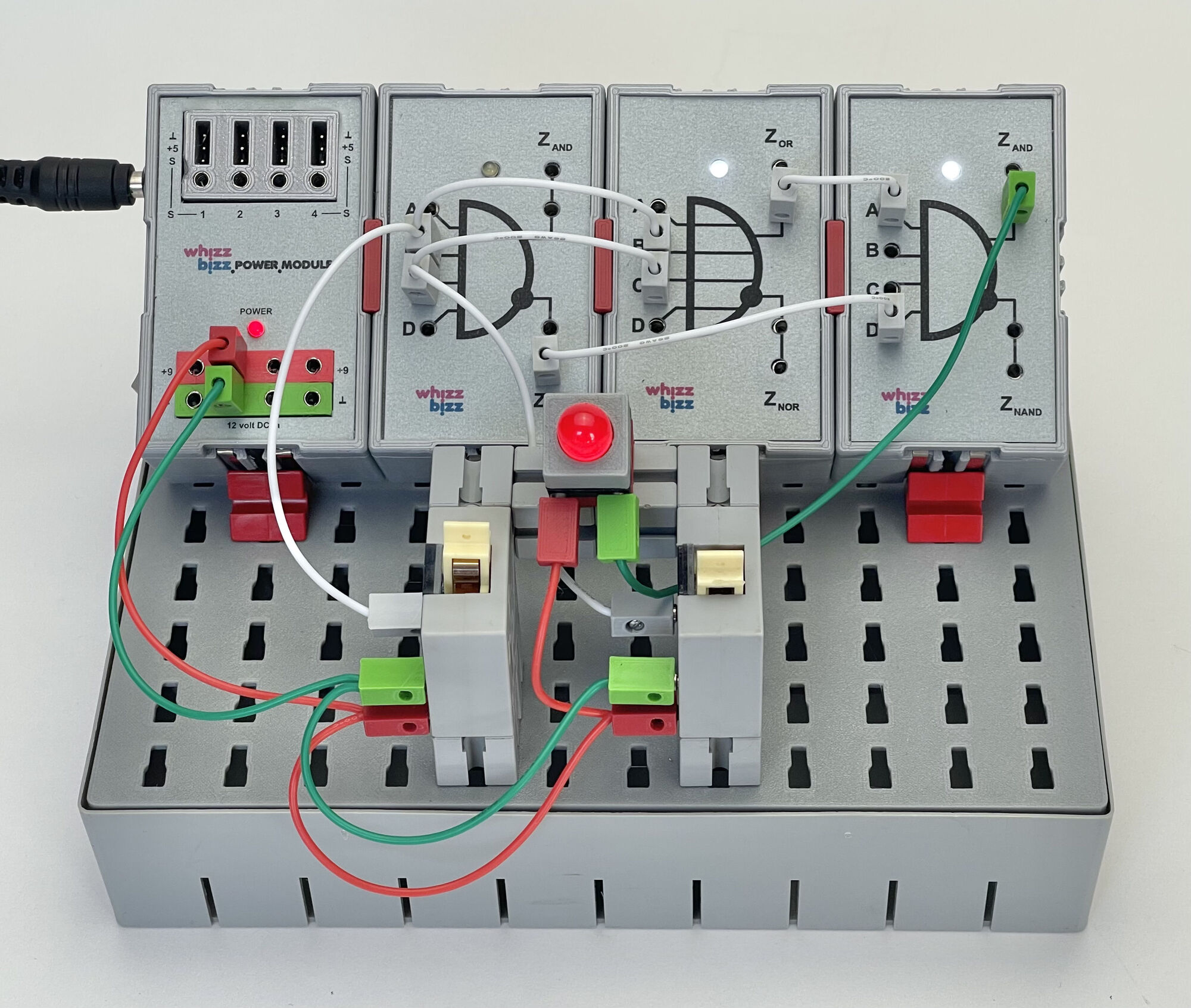
The structure, in which the two input signals can be entered using polarity reversal switches, is shown below. Although the XOR function can be created using existing components from the (former) fischertechnik range, this is obviously not very efficient in circuits where multiple XOR gates are required. This shortcoming led me to investigate the possibilities of expanding the well-known classic 'Silberlingen' arsenal with this useful logical function. Since I already had the necessary experience in recreating the original modules, this should be possible!
If we truly wish to create the XOR 'Silberling' that best matches the well-known AN (AND-NAND) and ON (OR-NOR) electronic building blocks, the following requirements would likely apply:
This last point may require some explanation because the XOR function differs from the AND and OR functions, which can easily be expanded with multiple inputs electronically. As long as an XOR has only two inputs (see the truth table on this page), the function is clearly defined. However, the situation changes when an XOR gate has more than two inputs. In that case, there are several possibilities for the logical behavior:
To align well with the classic fischertechnik AND and OR modules, the design should ideally have four inputs. However, it is difficult to determine which of the behaviors described above is preferable in order to keep the module universally compatible. After all, the behavior cannot be adjusted later. In addition, the electronic design of an XOR gate with four inputs is a completely different proposition in terms of electronic construction than the AN and ON logic gates from fischertechnik. After all, these modules can be easily expanded with additional inputs using diodes for the ‘wired logic’ at the input. However, the realization of an XOR function with multiple inputs proved to be much more complicated electronically.
After some puzzling, simulating, and experimenting, and testing (partial) circuits on a breadboard, I finally arrived at working circuits with both XOR switching behaviors. The design of a parity XOR turned out to be about as complex as the design of a ‘one hot’ XOR with four inputs. The parity XOR has a more sequential switching scheme of identical XOR scales with two inputs. The ‘one hot’ XOR, on the other hand, consists of a number of parallel-connected OR gates, each of which blocks all other OR gates when the relevant input becomes active.
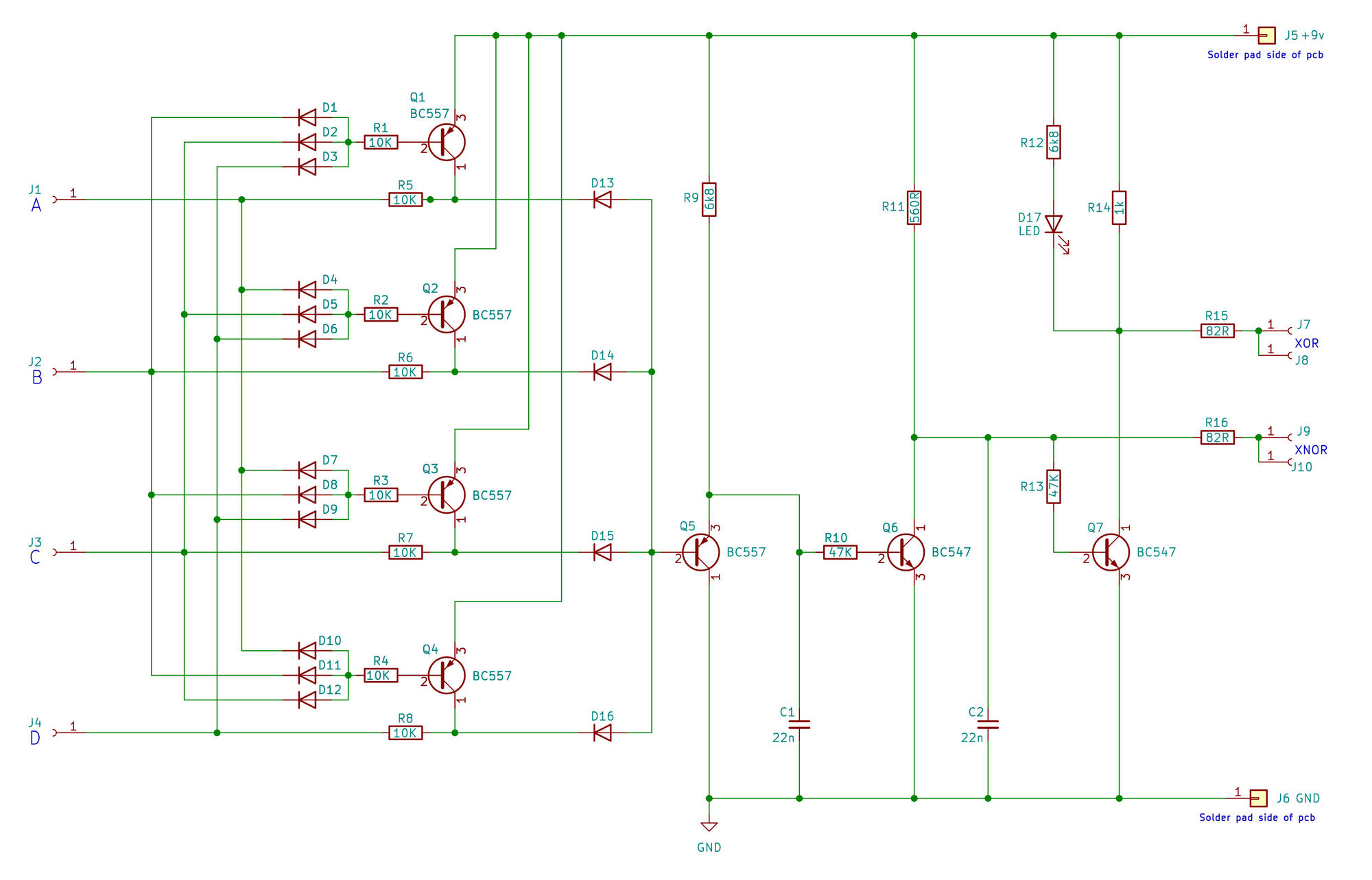
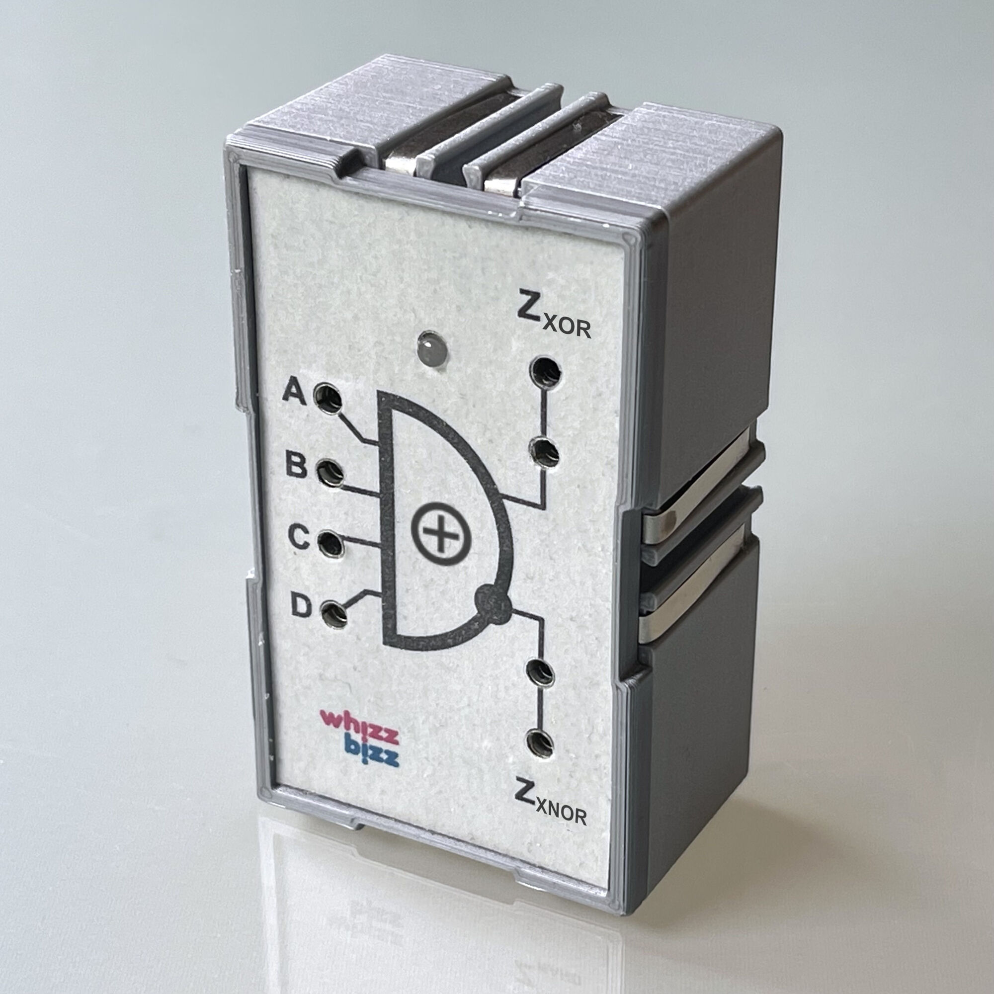
There is not enough space here to go into all the development steps and diagrams in detail. Therefore, I will limit myself (for those who are interested) to the diagram of the ‘one-hot’ XOR at the bottom left of the page, which led to the four-input XOR 'Silberling' shown in the photo. However, once this had been developed, its limitations also became apparent.
At first glance, the usefulness of two extra inputs seems limited, but perhaps more importantly, this means that a choice must be made between the two different XOR principles. With an XOR gate with only two inputs, this choice does not yet need to be made. In practice, therefore, XOR gates with simply two inputs will be more universally applicable.
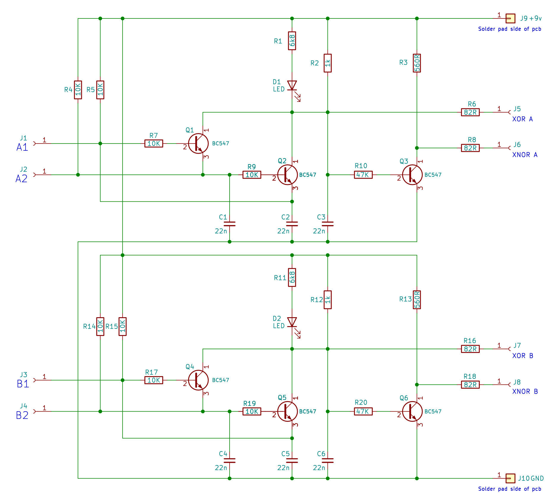
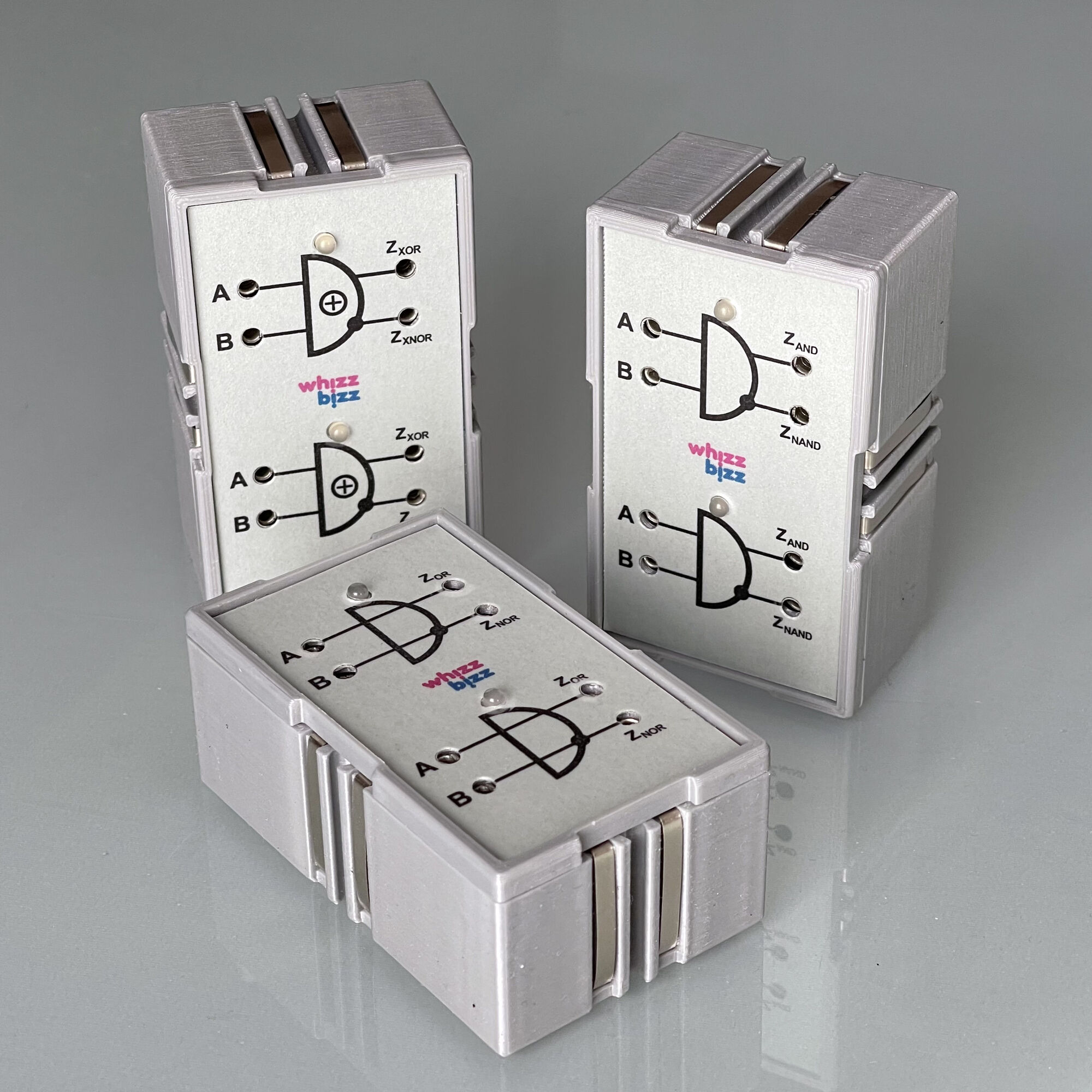
For most experiments, it therefore seems sensible to build modules that each contain two identical XOR gates, each with two inputs. The result of building such modules ourselves, according to the diagram below right, can be seen in the photo on the left. And while we're at it, it might be a good idea to also have a variant of the AND module in which two AND gates, each with two inputs, are housed in a single 'Silberling' enclosure.
We can use these new modules for the following digital experiments. For example, I always thought it would be educational and fun to build a so-called Half-Adder and Full-Adder from concrete logic gates. Click through to the next project to find out more.