Once I had built enough XOR modules (see previous project), this logical next step was a natural progression. With the self-built XOR modules, we can add numbers with a few additional digital modules (possibly from the original ‘vintage’ fischertechnik range)!
To add binary numbers, you follow a similar process to adding decimal numbers, but with the rules 0+0=0, 0+1=1, 1+0=1, and 1+1=10 (write down zero and remember the 1). You work from right to left, add the digits in each position, and write down the sum, carrying any carryovers over to the next column.
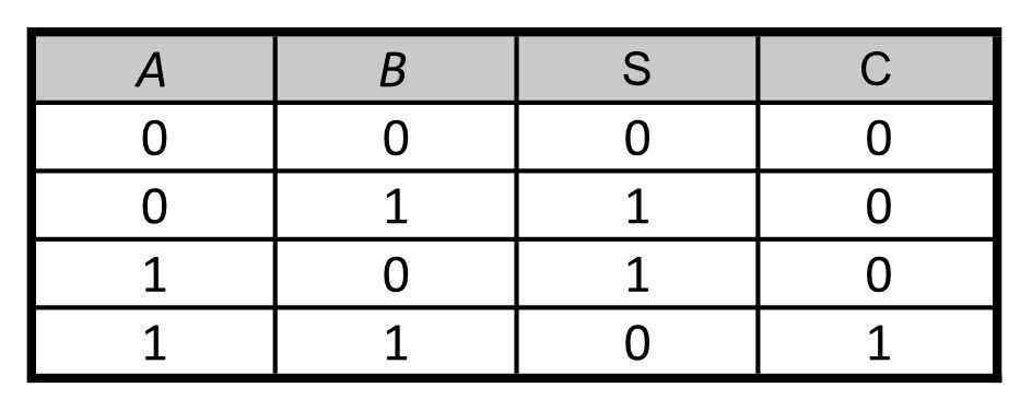
If we consider the (two) input signals of an XOR as binary ‘bits’, we can use the XOR functionality to add binary numbers. To do this, we create a so-called Half-Adder with which the ‘bits’ A and B can be added. The table on the right shows the answer, which we will call the output signal S.
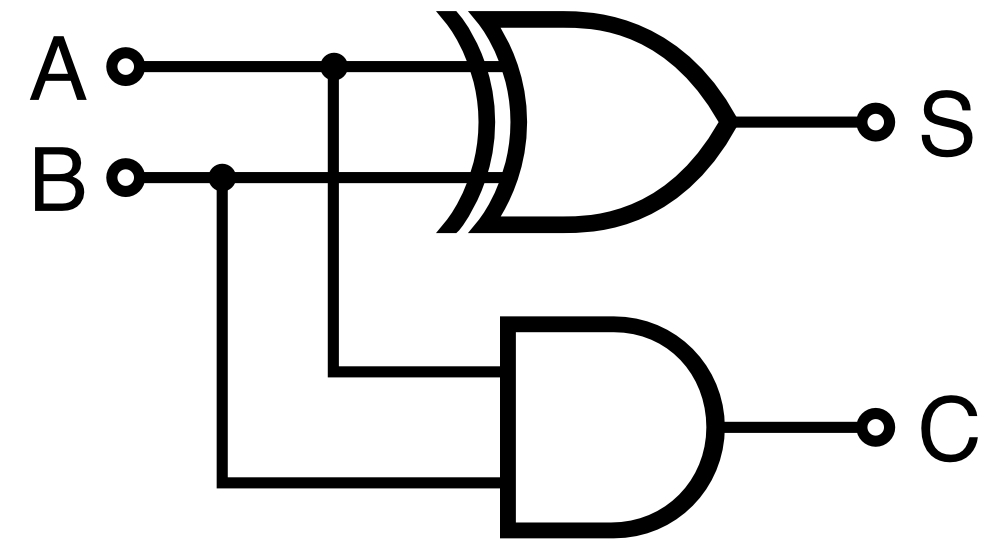
If both A and B represent the value 1 (the decimal number 1), the answer (the number 2) no longer fits in the current binary bit position. A second binary bit (representing the digital number 2) is then needed to indicate that the answer does not fit. This is output signal C, which represents the so-called carry bit. This addition of two bits to sum and carry is shown in the (truth) table above. Here it is easy to see that the S answer can simply be made with one XOR gate, while a simple AND gate is sufficient for the carry bit. We can draw this (using the so-called ANSI symbols) as shown on the right.
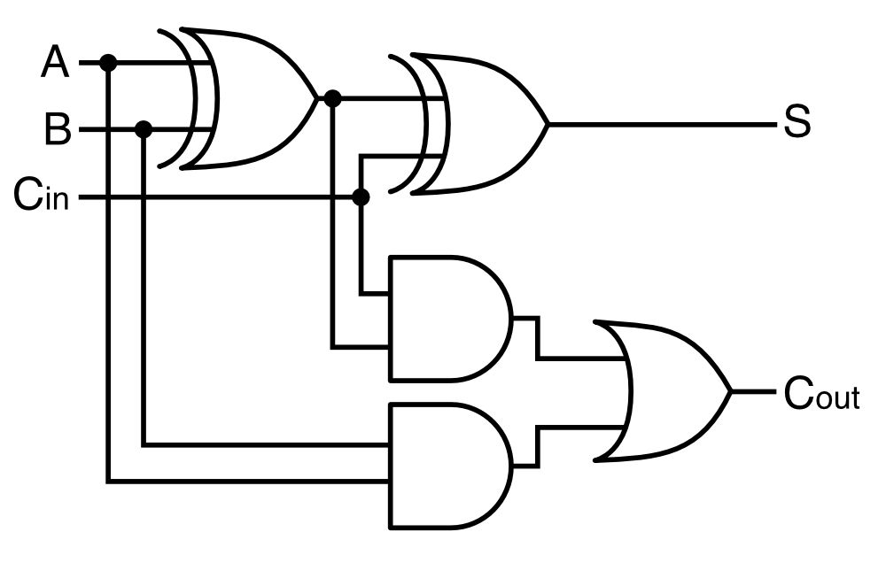
However, with a half-adder, we can only add the two bits at one binary position of the number. It would be better if we could also enter the overflow/carry bit at the input side. This would make it possible to connect several of these adders together and use the outgoing carry bit as an additional input for the next bit position. We call such an adder, which is obviously somewhat more complex, a full adder. This is shown schematically. Anyone looking for more information about adding binary numbers can find a wealth of information online relatively easily.
If we want to add more bit positions, for example two four-bit numbers, we need multiple full adders. The Cin is not used in the adder for the least significant first bit position, so a half adder is sufficient for this. The next three full adders, which represent the three higher-order bit positions, each have the Cout of each preceding lower-order adder connected as Cin. For the last and most significant full adder, the Cout is simply interpreted as the fifth bit.
Each four-bit input number can represent binary values from 0 (binary 0000) to 15 (binary 1111). The maximum answer, the decimal number 30 (binary 11110), therefore requires five bit positions: the four S bits and the last Cout.
If we use one half-adder and three full-adders for a four-bit adder, this would require seven XOR gates, seven AND gates, and three OR gates. Only two inputs are sufficient for each of these modules. The conclusion from the previous project, that models with only two inputs are the most flexible for the XOR and AND modules, therefore remains valid.
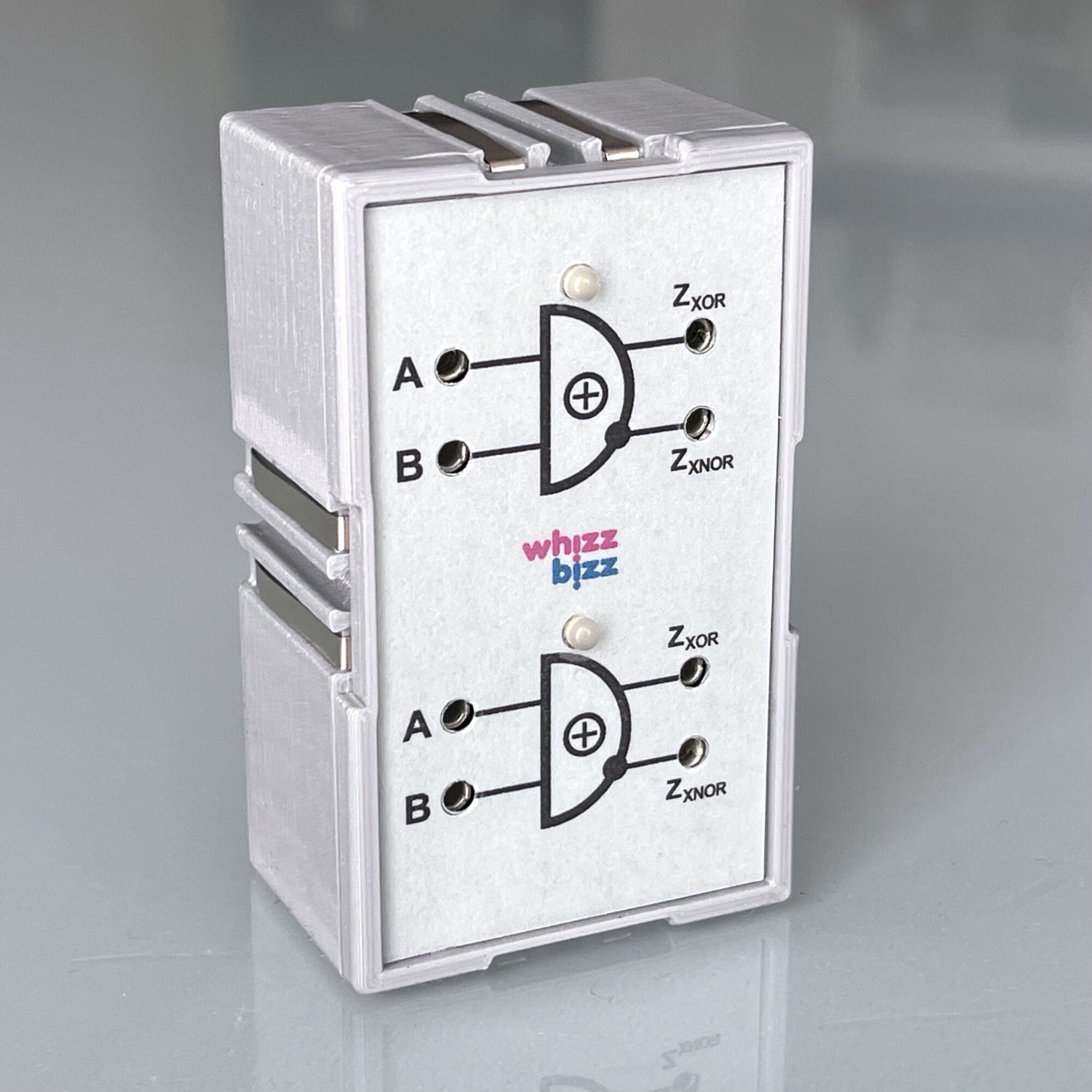
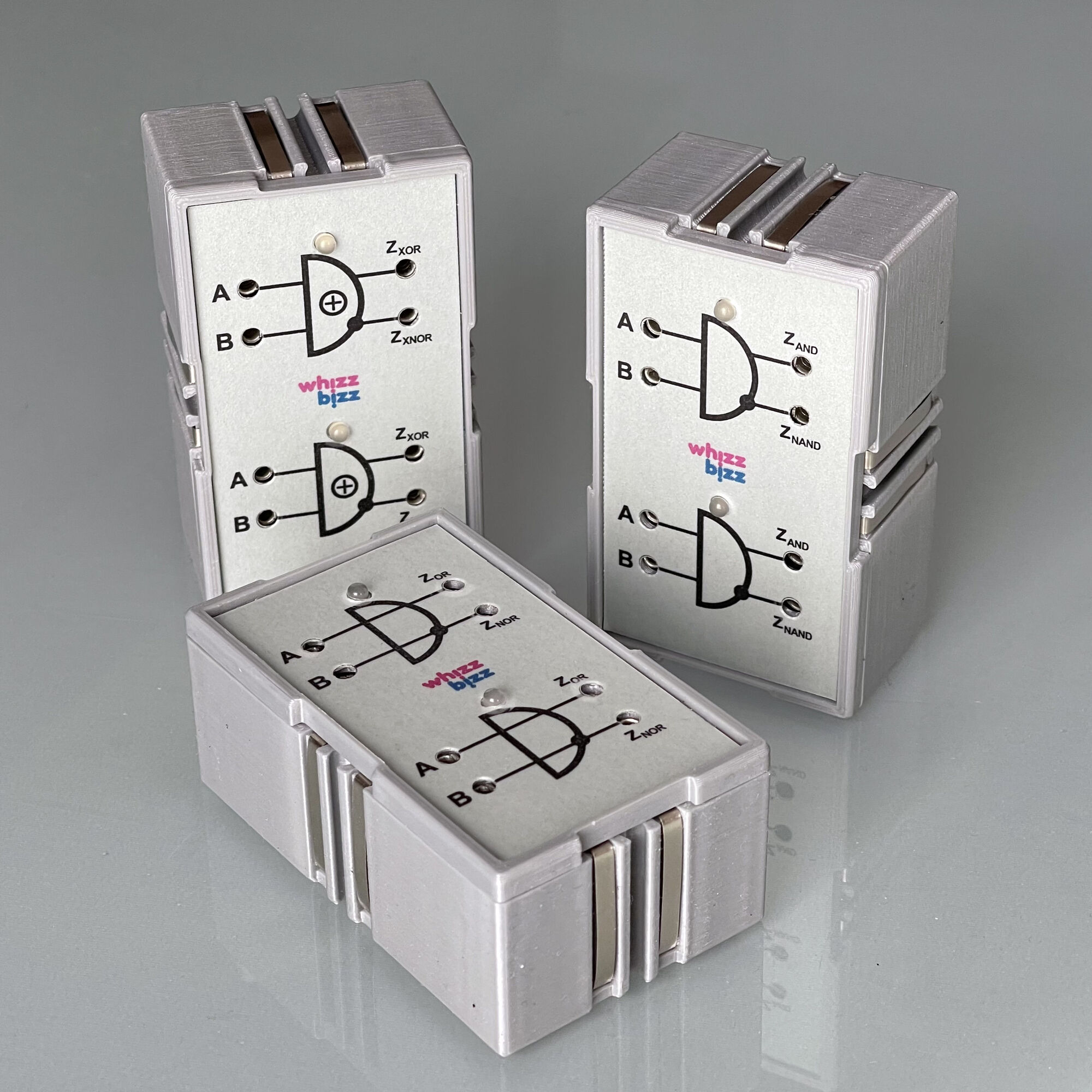
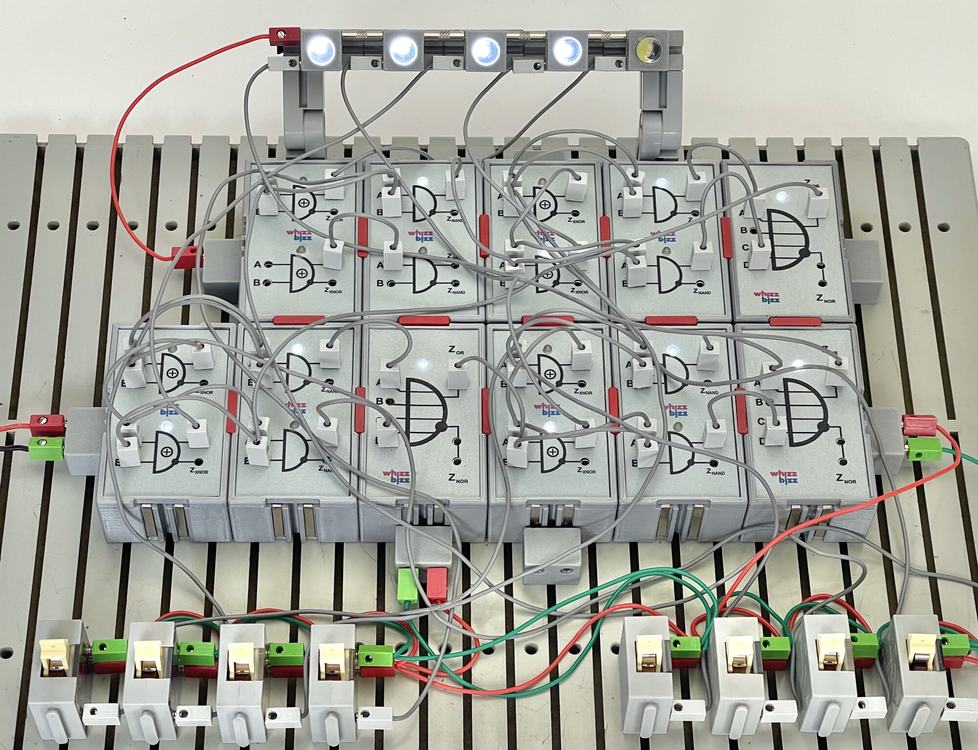
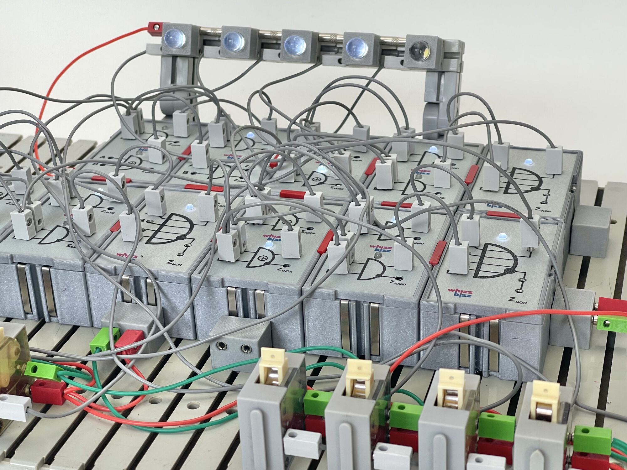
The images above show the result of the DIY project. The final diagram I came up with is also shown. I thought it would be useful to also have a variant of the AND module in which two AND gates, each with two inputs, are housed in a single ‘Silberling’ enclosure.
No sooner said than done. Under ideal conditions, the DIY modules shown in the photo would therefore be very suitable for building a four-bit adder with a minimum number of modules. The double OR gate with two inputs in the foreground is not strictly necessary. After all, two inputs from the existing ‘vintage’ fischertechnik OR module can also be used. However, since I developed a circuit board for the double AND module anyway, this became a nice ‘bonus’ that can always prove its space-saving services. After all, only two inputs are sufficient for most modules used in composite circuits.
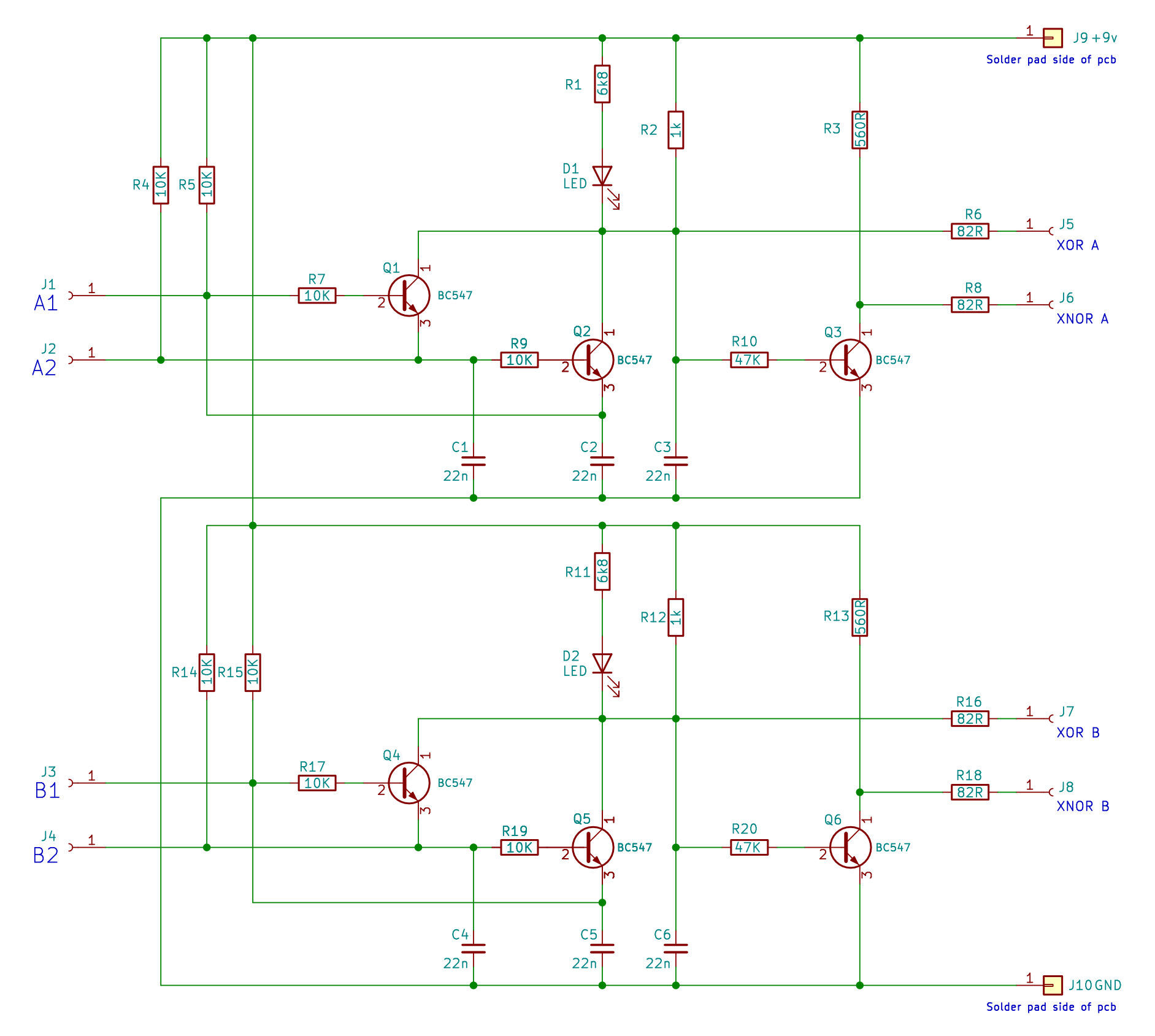
For the circuit diagram of the double OR and AND modules, please refer to the existing documentation (such as pages 49-62 of this German-language publication). The circuit is simply constructed twice and housed in a single ‘Silberling’ enclosure. Above (center image) is the circuit diagram of the double XOR gate that I arrived at after some experimentation. The double design is clearly visible in the diagram.
Once enough modules had been built, a comprehensive experiment was of course essential. I therefore built the aforementioned Full Adder for four bits. The ‘bits’ of the two numbers are entered using eight polarity switches. The binary ‘output’ of the summed number is displayed using five large (10 mm) LEDs in standard fischertechnik light bricks.
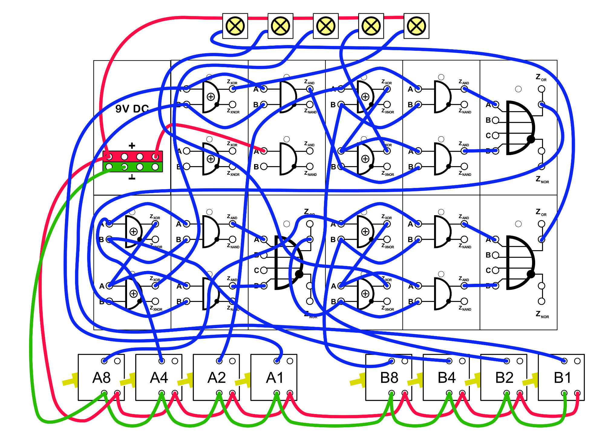
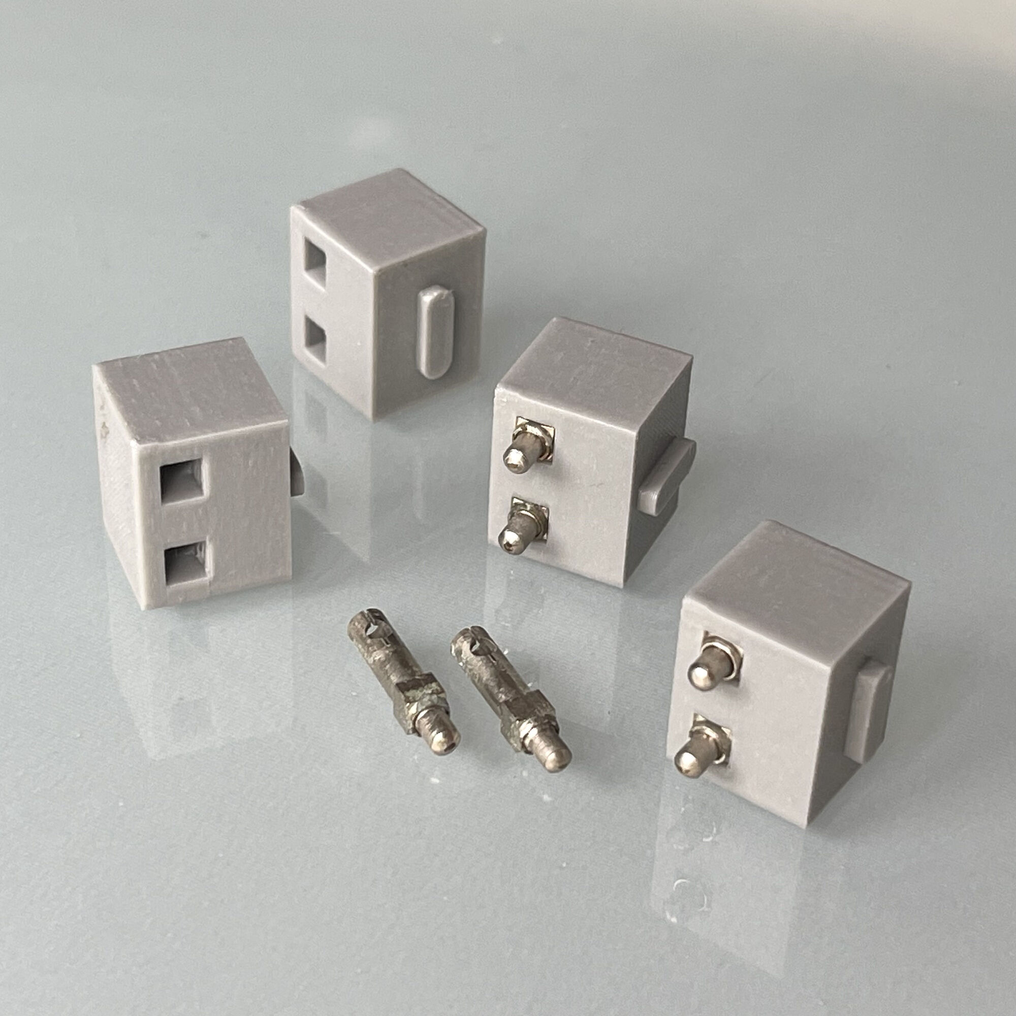
To connect the power supply, I experimented with an old idea. By incorporating the spring contacts from a Fischertechnik rotary switch into a 3D-printed building block, all modules on the building plate can be easily powered and the distribution of the power supply to the LEDs and switches can be optimized. Nevertheless, such ‘Silberlingen’ switch panels naturally tend to look like a plate of spaghetti.
It was interesting to first build the fascinating XOR function from existing modules and later add it to the arsenal as a DIY module. Anyone who, like me, still has a soft spot for experimenting with electronics modules can use it to build interesting and educational projects!