
In the previous part we were introduced to a current sensor, the INA3221. We can use a ready-made board with this chip on it for our experiments. Unfortunately, the board needs some tweaking to make it usable to monitor three truly independent voltage channels or buses.
In this sequel, I designed the circuit, drew the schematic and made a test setup with the modified module, so that we can start testing with current and voltage measurements.
A useful SMD chip to monitor voltage and current is the INA3221 [info & datasheet]. This chip communicates via the I2C bus and makes it possible to monitor three independent voltage channels. By measuring the voltage difference per channel across a (known, 0.1Ω) shunt resistance, the current and power consumption can be determined.
The great thing is that the chip can not only be read via the I2C bus, but that we can also configure the chip by writing certain registers. The INA3221 can then signal whether the measured values remain within adjustable limits and emit a signal if, for example, the current exceeds a set value. This allows the chip to operate a small relay that can act as an adjustable automatic fuse. The module is then well protected against (overheating due to) too high currents. Handy when testing and experimenting!
Both the 'Warning' and 'Critical' thresholds can therefore be programmed in the chip over the I2C bus. This makes it possible to ultimately make the module configurable via push buttons on the front. An option to store this maximum allowable current per bus in the Arduino's EEPROM would of course be nice. As a result, these settings would be preserved in the module and not have to be configured for each use.
It would be nice if the new voltage module has the same form factor as the Zauberling. As a result, it is now logical to accommodate the circuit on a 'sandwich' of two printed circuit boards. For this reason, the scheme has also been cut into two parts.
The lower circuit board is located at the bottom of the housing, produces the various voltages from the incoming 12 volts from the DC adapter, and takes care of the measurements with the INA chip. The relay, which can soon serve as an automatic fuse, is also housed here.
The various connectors, push buttons, LEDs and the small screen can find a place on the top circuit board. The Arduino Pro Mini will also have to be accommodated here, hanging upside down. In order to optimally use both sides of both printed circuit boards, SMD mounting will be chosen for (almost) all components.
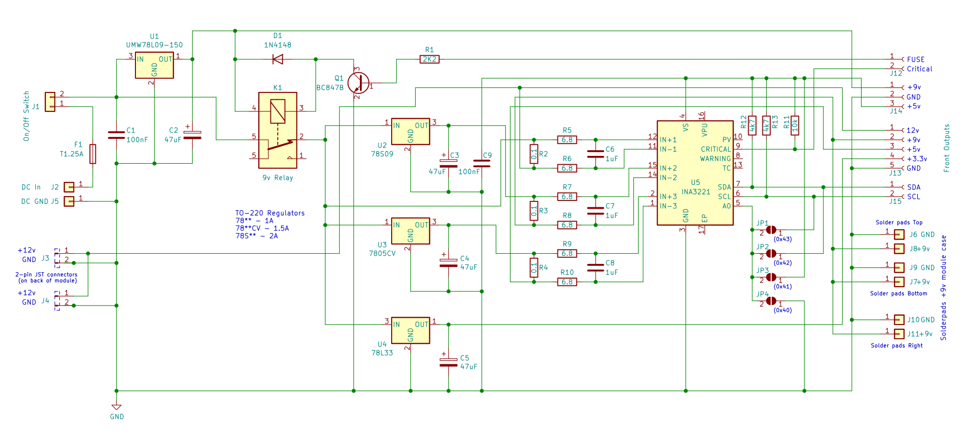
The 12 volts from the external DC adapter will enter the case via a DC connector. After a physical fuse and the on/off switch, the 9 volts system power is made on this PCB. This voltage does not flow across the contacts of the relay, which forms the automatic fuse. This 9 volts will later go on to PCB 2, where 5 volts will be made on the Arduino Pro Mini board. This 5 volts is used by the microcontroller on the other circuit board itself, but it also comes back so that the INA chip can be fed with it.
Three voltages are created from the incoming 12 volts. They're flowing across the normally closed contact of the relay. The 3.3 volts simply flows through to the other circuit board to the front connectors on the top circuit board in the case. This PCB accomodates the connectors, the display and push buttons on the front. The other three voltages run over their corresponding measuring channels of the INA chip, across a 5 pin connector between the circuit boards, where they will be made available on the front of the module.
The image on the right can be found in the datasheet of the current sensor and shows the principle of the measurement. On the left, the three shunt resistors over which the measurement takes place are visible. On the sensor board they are three big 2 Watt SMD resistors (with R2512 housing). These resistors are always in series with the 'load'; e.g. the connected device. The alternately measured values of each bus are sampled by an AD converter (ADC, center) and stored in registers of the chip that are retrievable via the I2C bus (right). Also on this interface side of the schematics are the various control and alarm signals of the chip. For this project, only the 'Critical' signal is used to activate the automatic fuse if the configured draw current limit is exceeded.
The I2C bus lets us configure at which current the 'Critial' signal of the relevant bus should kick in. This signal is read into input D8 of the Arduino (see PCB 2, diagram below). As soon as it is active, the 'Fuse' signal can be given via output D9 to energize the relay via a transistor. As a result, all voltages at the outputs are immediately dropped and the module is protected against excessive currents, such as due to short circuits.
The system voltage of 9 volts and the 3.3 volt output can be supplied by SMD types voltage regulators of up to 100 mA, for the 9 and 5 volt voltage regulators of the output voltages it is wiser to choose heavier types such as the 78S05 (up to max. 2A). We don't have to worry about the 12 volt input voltage of the DC adapter that runs through the front of the module, but also can be looped through on the back of the module. The maximum current the adapter can supply applies there. These will of course have to be within the limits of the physical fuse. If we design the PCB with '1 ounce' copper thickness and a copper track width of 1.5mm, it may handle a current of up to 1.5 Amperes without any problems. For higher currents, you may have the PCB manufactured with thicker copper or tin the PCB tracks of these main voltages.
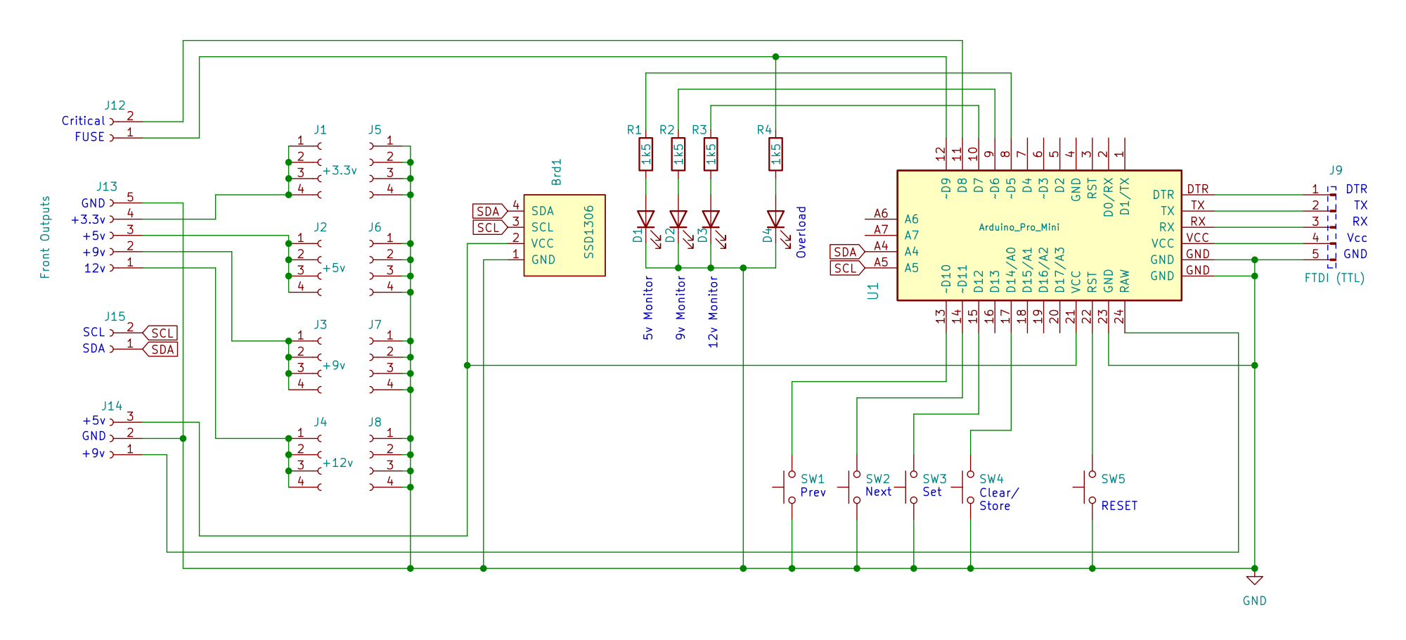
The schematic of the printed circuit board that is located at the top of the case, under the front cover, is shown above. This printed circuit board has the display and the connections on the front for the various voltages of 3.3, 5, 9 and 12 volts.
The most important part here is of course the Arduino Pro Mini, which is powered from the other PCB and makes the 5 volts it makes available to PCB 1 for the INA chip. The 'Critial' signal from this current sensor comes in here, and if the automatic fuse has to intervene, we can send the 'Fuse' signal back here so that the relay and thus the automatic fuse are activated. At such a moment the 'Overload' LED will also turn on.
There are buttons to cycle through the different channels or buses on the screen. The small SSD1306 display communicates over the same I2C bus as the INA chip. LEDs indicate which voltage is displayed on the screen. There is a 'Clear' button to reset the current peak shown on the display. And there is a button to enter the configuration mode so that we can configure the current threshold per bus. These can then be stored in the Arduino's EEPROM by pressing the 'Store' button if desired.
On the far right, the FTDI programming signals are passed to a connector on this PCB to be able to flash the Arduino via the USB bus. Since the module only needs to be updated sporadically with new firmware, this connector does not have to be easy accessable. So it's okay if it is accessible under the top cover of the module.
I've first build the circuit on a breadboard. Top left the two larger voltage regulators, with underneath the smaller 3.3 volt and 9 volt regulators for the system voltage. The relay and the switching transistor for it have also been placed and connected.
The white push buttons can be used to select the readout on the screen. The blue push button to enter the current threshold setting mode. This button can also be used to reset the held peak current message on the screen. Finally, the set value can be saved in the EEPROM with the red button.
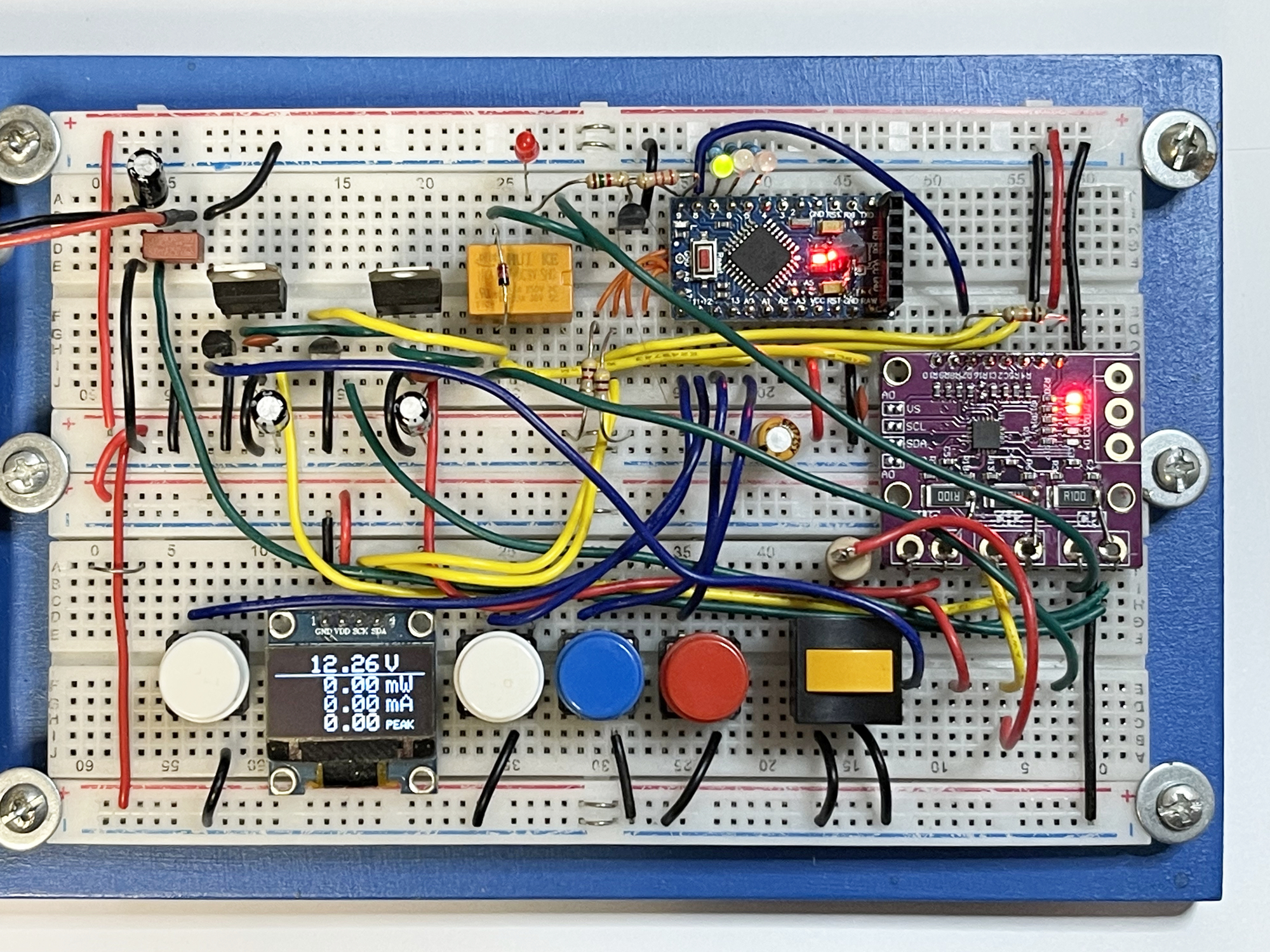
The orange button is temporary. Allows a 100Ω power resistor to be connected to an output for testing purposes to play with current variations and test the fuse. With the hardware set up like this, it was time to write an Arduino Sketch to give it a try.
I found a software library from SwitchDoc Labs for communication with the INA chip. Unfortunately, it was rather rudimentary and could only read measured values from the chip's registers. There were no routines yet for writing configuration values to the chip's registers via the I2C bus. This is of course something that is necessary if we want to use the hardware monitoring through the chip. Of course it is possible to monitor the current in the software, but since the chip offers the possibility to monitor it hardware, I wanted to use that. So I expanded the library so that I could also write the Critical Alert value into the chip for each bus.
Here is the Arduino Sketch that I used for the accompanying video. This, including the modified library, can also be found on GitHub.
// Test INA3221
// Whizzbizz.com - Arnoud van Delden - June 2022
// See https://www.whizzbizz.com/en/power-module-part2
//

#include
#include "SDL_Arduino_INA3221.h"

// Initializing INA3221
SDL_Arduino_INA3221 ina3221;  // Default address 0x40 on I2C bus

// The three channels/busses of the INA3221
#define VOLTAGE_MAIN_12V 1
#define VOLTAGE_9V 2
#define VOLTAGE_5V 3

// Static calibration offset for current per bus, will be exemplaric...
#define CAL1 0 // 12v bus: Compensate for 9, 5 and 3.3 voltages that are being produced from the fuse-switched measured 12v
#define CAL2 0  // 9v
#define CAL3 0  // 5v

// Define I/O pins
#define BUS1_LED       7
#define BUS2_LED       6
#define BUS3_LED       5
#define READ_CRITICAL  8
#define AUTO_FUSE      9

bool logging = true;      // Serial logging during development...
bool ext_logging = true; // Show all bus values during debugging...

uint16_t binValue;
bool autoFuse = false;

struct INA3221_Bus {
  char* Label;
  uint8_t Channel;
  float shuntvoltage = 0;
  uint16_t shuntvoltage_raw = 0xFF;
  float busvoltage = 0;
  uint16_t busvoltage_raw = 0xFF;
  float current_mA = 0;
  float current_mAMax = 0;
  float currentOffset;
  float loadvoltage = 0;
  uint16_t currentLimit;
  uint16_t currentLimitSaved;
};

INA3221_Bus Bus1, Bus2, Bus3;
INA3221_Bus *currentBus = &Bus1;

void setup(void) {
  if (logging) Serial.begin(115200);
  if (logging) Serial.println(F("Test INA3221"));

  // Set pin-modes...
  pinMode(READ_CRITICAL, INPUT);
  pinMode(AUTO_FUSE, OUTPUT);

  // Initialize busses and INA3221...
  Bus1.Label = "12V";
  Bus1.Channel = VOLTAGE_MAIN_12V;
  Bus1.currentOffset = CAL1;
  Bus2.Label = "9V";
  Bus2.Channel = VOLTAGE_9V;
  Bus2.currentOffset = CAL2;
  Bus3.Label = "5V";
  Bus3.Channel = VOLTAGE_5V;
  Bus3.currentOffset = CAL3;
  ina3221.begin();
  if (logging) {
    Serial.print(F("INA3221 getManufID="));
    Serial.println(ina3221.getManufID());
  }
  delay(200);
}

void loop(void) {
  // Read individual busses
  readBus(Bus1);
  delay(200);
  readBus(Bus2);
  delay(200);
  readBus(Bus3);
  delay(200);

  if (ext_logging) {
    logBus(Bus1);
    logBus(Bus2);
    logBus(Bus3);
  }

  delay(1000);
}

void readBus(INA3221_Bus &Bus) {
  Bus.busvoltage = fabs(ina3221.getBusVoltage_V(Bus.Channel));
  Bus.busvoltage_raw = ina3221.getBusVoltage_raw(Bus.Channel);
  Bus.shuntvoltage = fabs(ina3221.getShuntVoltage_mV(Bus.Channel));
  Bus.shuntvoltage_raw = ina3221.getShuntVoltage_raw(Bus.Channel);
  Bus.current_mA = fabs(ina3221.getCurrent_mA(Bus.Channel)-Bus.currentOffset);
  if (Bus.current_mA > Bus.current_mAMax) Bus.current_mAMax = Bus.current_mA;
  Bus.loadvoltage = fabs(Bus.busvoltage + (Bus.shuntvoltage / 1000));
}

void logBus(INA3221_Bus Bus) {
  Serial.print(F("   "));
  Serial.println(Bus.Label);
  Serial.print(F("   Bus Voltage:       ")); Serial.print(Bus.busvoltage); Serial.println(" V");
  Serial.print(F("   Bus Voltage HEX:   0x")); Serial.println(Bus.busvoltage_raw, HEX);
  Serial.print(F("   Shunt Voltage:     ")); Serial.print(Bus.shuntvoltage); Serial.println(" mV");
  Serial.print(F("   Shunt Voltage HEX: 0x")); Serial.println(Bus.shuntvoltage_raw, HEX);
  Serial.print(F("   Load Voltage:      ")); Serial.print(Bus.loadvoltage); Serial.println(" V");
  Serial.print(F("   Current:           ")); Serial.print(Bus.current_mA); Serial.println(" mA");
  Serial.println("");
}

uint8_t readCriticalStatus() {
  // Reads the mask/enable register of the INA3221 after Critical Warning Alert
  uint16_t binValue;
  ina3221.wireReadRegister(INA3221_MASK_ENABLE, &binValue);
  binValue = (binValue>>7);
  if (binValue==4) {
    currentBus = &Bus1;
    return 1; // Bit2=Bus1
  }
  if (binValue==2) {
    currentBus = &Bus2;
    return 2; // Bit1=Bus2
  }
  if (binValue==1) {
    currentBus = &Bus3;
    return 3; // Bit0=Bus3
  }
  return 0;
}
The next step is the challenge of pressing the above circuitry into a 'Silberling' housing. It is clear that it then becomes necessary to omit the relatively large sensor board (almost twice as large as the Arduino Pro Mini!) and to opt for an own PCB layout on which the sensor will be placed directly as an SMD component.
In the last part of this article we'll see if I can design the two printed circuit boards, the 3D printable housing and the front. I'm going to actually put the module together and see if that works.