
In the 1970s, fischertechnik produced the so-called 'Silberlings'. Each small module had its own function, built up with (then modern) electronics. The modules could be linked together to create composite functions and to experiment with and learn about the wonderful world of electronics.
They certainly contributed to my interest in electronics. However, in my youth I had very few of these modules. Now, nearly half a century later I am trying to make a backwards-compatible variant with an Atmega328P microcontroller. The challenge of course is to craft something that will be compatible with the traditional heritage of yesteryear.
The 'Silberling' was for many the introduction to the elusive magical world of electronics long ago. This wizardry has since been expanded to include contemporary alchemists such as microcontrollers and computers. Yet a modern sorcerer's apprentice muses on affiliation with the magicians of yore. Could a magical bridge be built between the two universes? In this first part we dive into the wormhole and look at the possible hardware for such a sorcerer's apprentice. Because how can an inquisitive magician wonder and enchant without the right attributes? The wand must be in order!
Although now about fifty years old, the traditional fischertechnik Silberlings remain magical boxes. Many were once enchanted by their magic and today, experimenting with the classic functionality of discrete electronics continues to be enticing. If only to actually build older experiments from original documentation. So although the silver of the Silberingen has sometimes yellowed, they have not yet been completely forgotten. On the contrary. It even turns out that copying it appeals to the imagination.

Many 'fischertechnk-technicians' now use more modern techniques in their experiments. And fischertechnik itself also evolved. Boxes such as the Elektronik Praktikum, the Hobbylabor and the IC-Digital-Praktikum were followed by interfaces for microcomputers and eventually a programmable controller, which is getting its latest incarnation around this time. In addition, the range of Arduino-based microcontrollers is of course growing with which almost all discrete functions and automation issues can be solved in a software-programmable way, completely without plugging any plugs.
Nevertheless, it still beckons to be able to program hardware with wire connections and plugs with a modular system such as the trusted Silberlings. However, with the E-Tec, Elektronik and Robotics modules, fischertechnik gave up direct compatibility with this heritage. Although the various logical functions return in these modules, they still feel too limited for the true developer because they cannot be provided with their own adapted or additional software.
The idea was born to investigate whether the traditional domain of the Silberlings could be expanded with the power of microcontrollers. With some modern alchemy it should be possible to build a connecting module, both literally and figuratively. A new Silberling that is backward compatible in form factor, digital logic and analog voltage levels. A module that makes it, in addition to the classic micro switch, photo-resistor and more modern photo-transistor, possible to use more contemporary sensors such as IR-obstacle detectors or hall-effect sensors as well. Ideally, it would figure out the threshold values of sensors itself and combine TTL levels with the 9-volt 'negative logic' world of the classic Silberling. If such a module can also control heavier consumers directly without a relay, and maybe even move servos at the same time, it starts to become very magical!
Inspired by the experiments of others, I also built some flip-flops and switchable AND/OR gate Silberlings. But as I became more at home in the world of microcontrollers, the desire to work directly with the Silberlings grew stronger and stronger. A flexible and programmable Silberling for specific own applications emerged.
Such a wizard should be able to work seamlessly with the classic Silberlings. And because of the programmability, this sorcerer's apprentice could be taught new tricks over and over, allowing the functionality of the mentioned fischertechnik modules to be adapted and improved. A real sorcerer's apprentice, a real 'Zauberling'...('zauberen' means 'conjuring' in the German language)
In the photo opposite you can see where this kind of daydreaming and tinkering can lead.
I first built the control of Mr. Lemniscate with the classic Silberlings, but it still felt like a detour to have to energize the coil of a relay magnet to make another electromagnet work. Apart from the unnecessary noise and wear on the contacts, the switching moment had to be turned a few degrees, for example, to compensate for the 'double delay' required by energizing the two solenoid coils in succession.
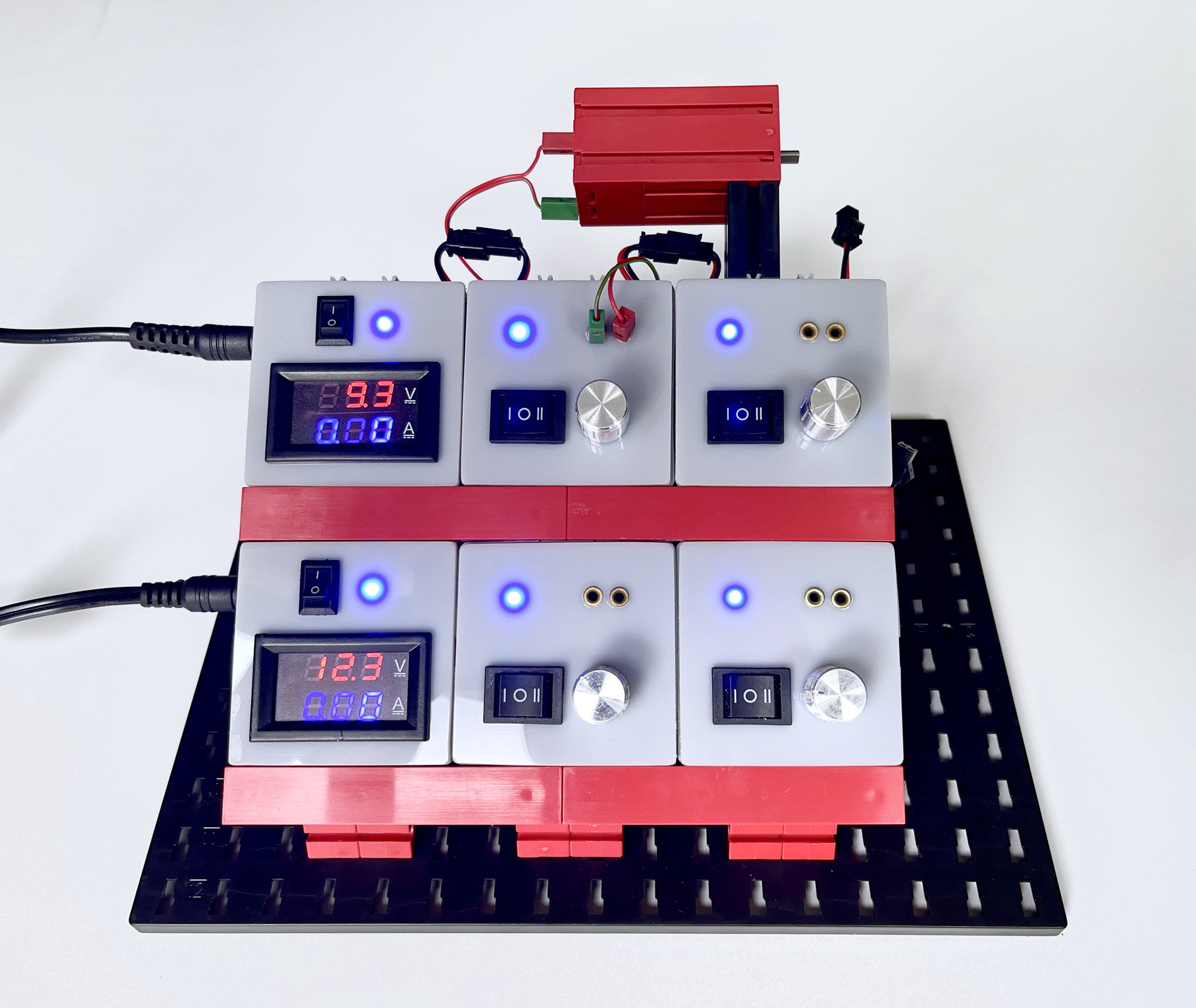
In addition, it became clear that the 9 volt power supply of the fischertechnik rectifier module was not sufficient for the heavier electromagnets used in the model. This led to a self-build speed control and flip-flop module in fischertechnik cassettes. The flip-flop module received driver outputs that could directly control an electromagnet or motor without an additional relay module. Its external power supply can be looped through with plugs. This keeps the front free of the necessary loop-through and connection cables.
I applied the same principle to a generally usable 'controlpanel' with speed controls, which I housed in fischertechnik cassettes. That eventually led to the panel in the photo you see here.
Various articles and realized products from other fischertechnik tinkerers inspired the building. The lively discussions on the fischertechnik forum on this subject also showed that the Silberlings still appeal to the imagination.
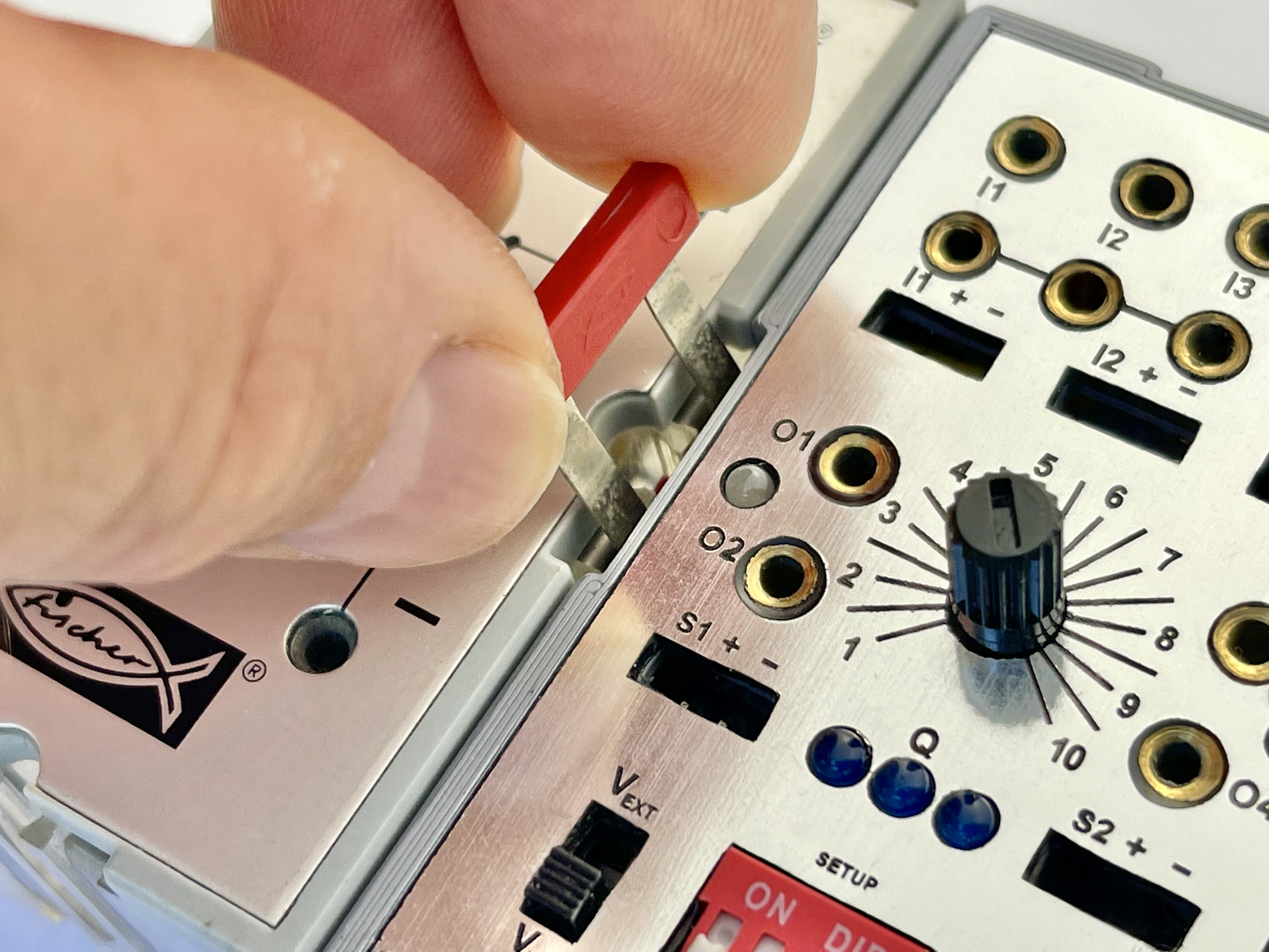
However, the modules built in the existing fischertechnik containers do not always combine optimally with the traditional 'Silberlings'. Offering and looping through the necessary power supply often requires a disproportionate amount of space due to the relatively large fischertechnik connection plugs. While an elegant technical feature of the Silberlings is that the necessary distribution of the power supply does not have to be made between the connections and controls on the front: the supply voltage can be bridged with two-pole connection clips.
For more demanding power consumers such as electromagnets and motors, however, it must be possible to connect an external power supply so that they can be continuously controlled via the power outputs without unnecessarily burdening this regular power supply.
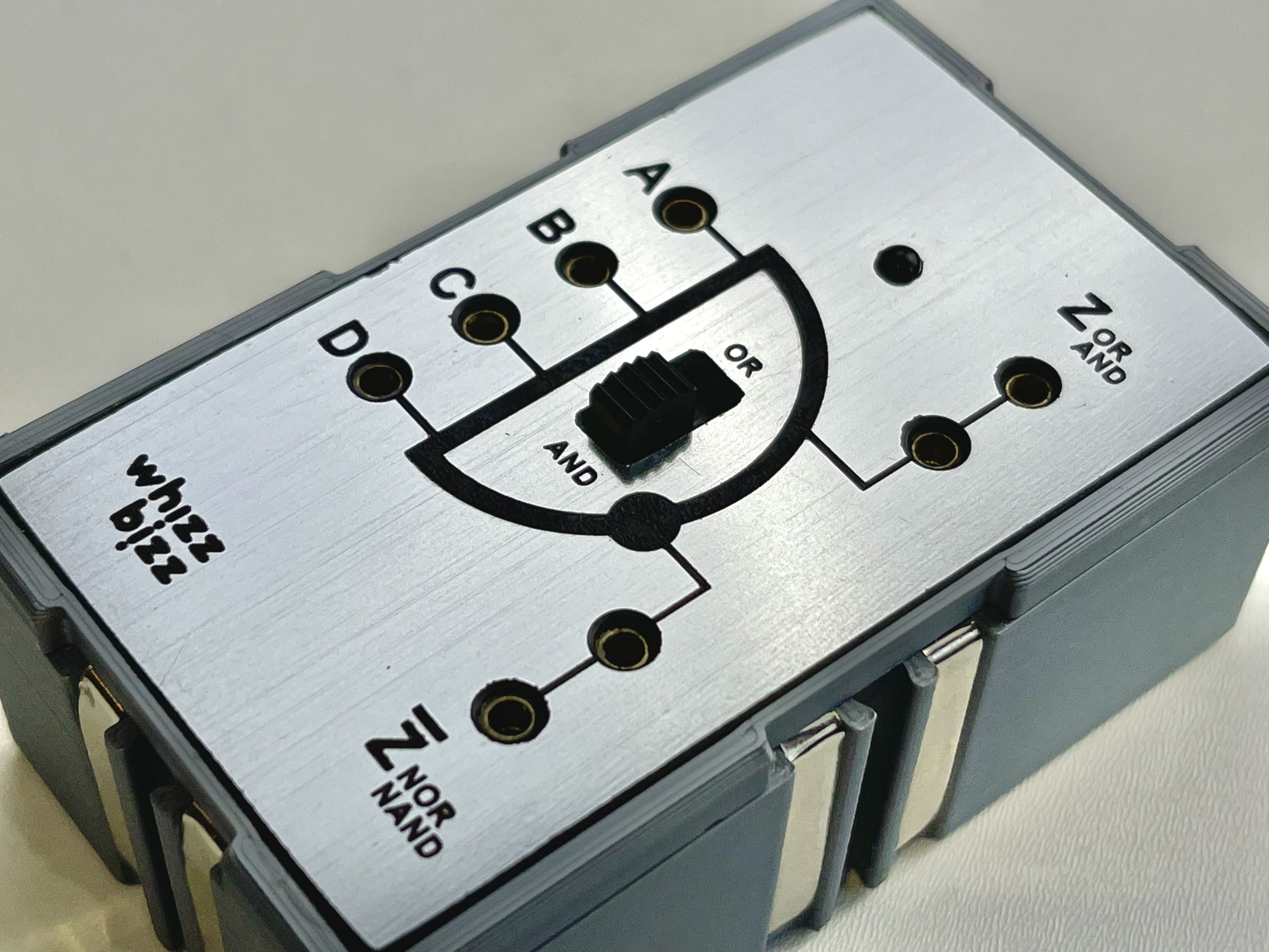
In the meantime I had combined and modified some excellent 3D Silberling designs in Blender so that the last wish above could already be realized. See the 3D design I published on Thingiverse. I built a switchable AND/OR with it that did not yet require an external power supply and could thus be supplied with power directly from the rectifier module h4 GB. At this point, the compatibility with the Silberlings was already successful.
The result is already starting to look a lot like the Silberlings. But the search for the most ideal material for making the front panels is not over yet. The original material is anodized aluminum sheet in which the image has been photographically etched. However, I have not yet found an address where it is possible to have a few pieces produced affordably.
In addition to being able to professionally print the 3D housings for me, my skilled friend Dimitri Modderman experimented with various materials and lasers to find the best way to fabricate the faceplates. We have not yet found the most suitable material where one laser can laser both the captions and the holes tightly and neatly.
For now, we came up with a 2.6 millimeter thick black plastic plate for the prototype, which is covered with a wafer-thin silver-coloured foil. However, the surface of this material is very delicate in finishing, cutting all square slots and holes. In addition, this material shines more than the original Silberlings. In short, the result is already very nice, but perhaps we will find an even more optimal process for this in the future.
The possibilities of the common microcontrollers, but also the functionality traditionally offered by fischertechnik in, for example, the E-Tec module, kept me busy. So I let my imagination run wild, dreamed my ideal magical Silberling and soon had a list of wishes:
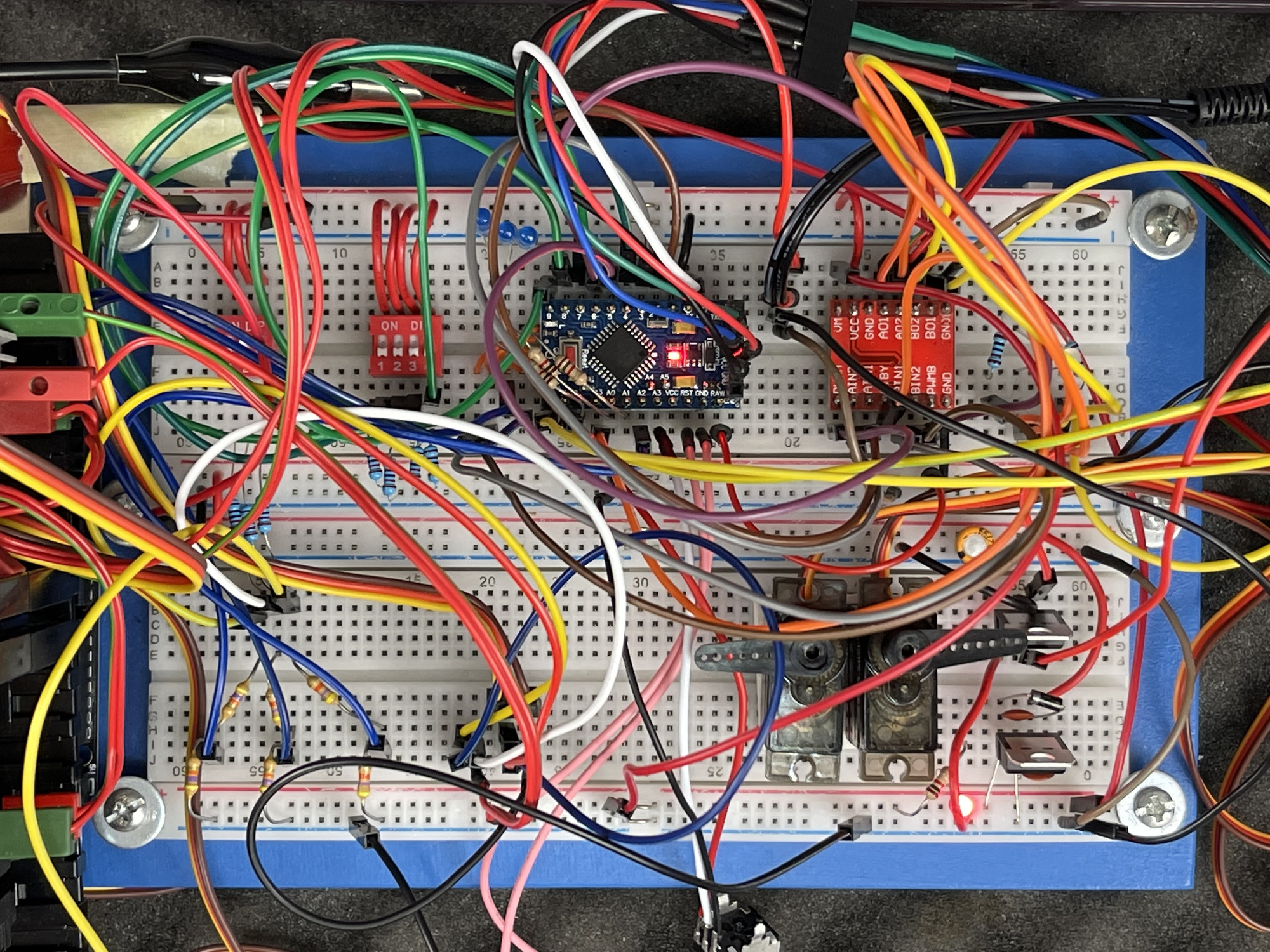
The interior space of a Silberling housing measures only 38 by 68 millimeters. As a result, the regular Arduino Uno with its 53.4 x 68.6 mm is already too wide. Not to mention the even bigger variants like the Mega and Due (53.4 x 101.52 mm). A Raspberry Pico, ESP32 or Arduino Nano will fit, but the Arduino Compatible Pro Mini Atmega328P gave the best ratio between the number of available input/output pins and dimensions. This is an extremely small Arduino, which, like the Arduino Uno, runs at 5V at 16 Mhz and can be programmed on the computer from the Arduino IDE environment that is familiar to most developers.
This very small board measuring only 34 by 18 mm offers 20 inputs and outputs. Including six analog inputs and six outputs with pulse width modulation (PWM).
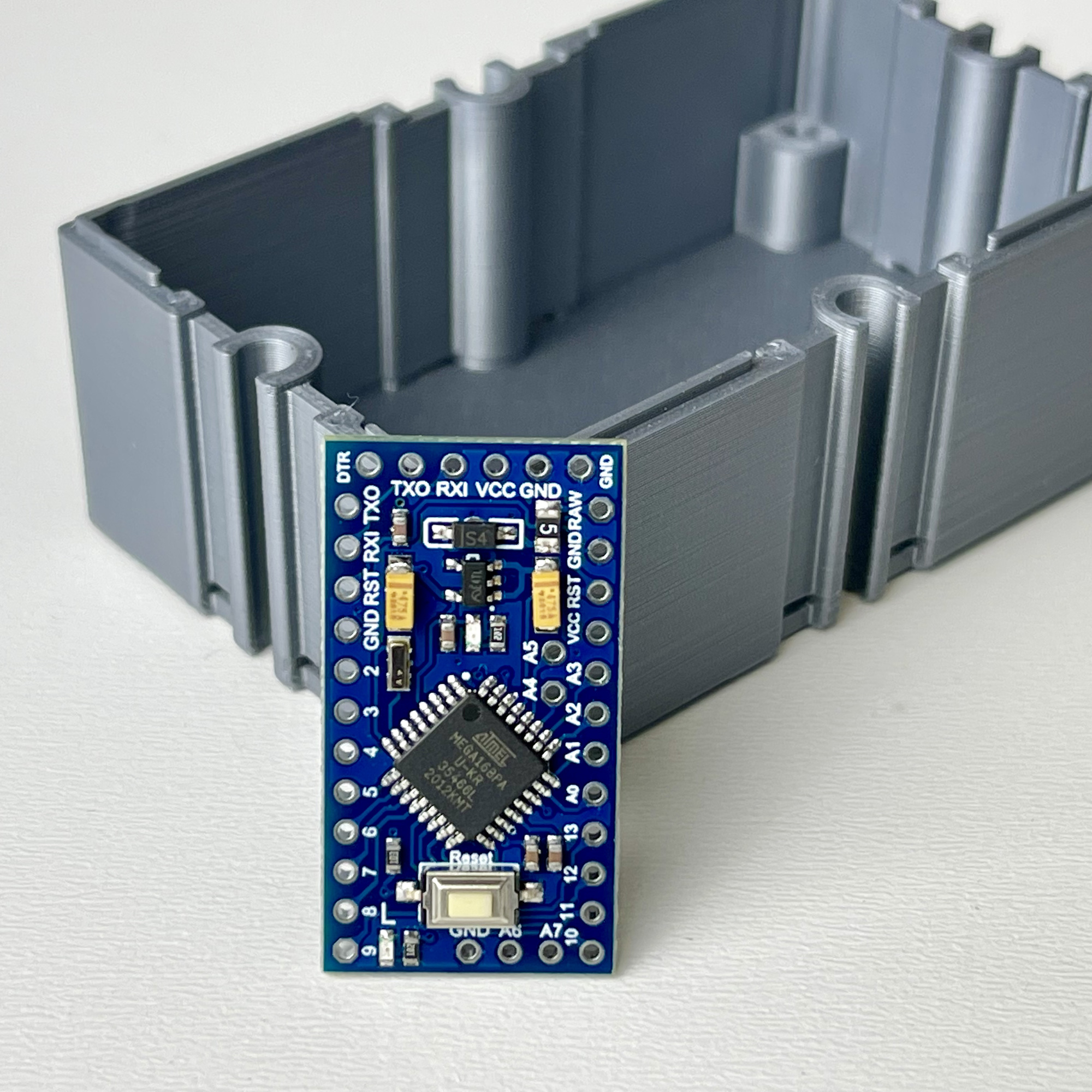
It seems that the Pro Mini Atmega328P could be made so tiny, because only the strictly necessary is included on the circuit board. It does have a reset button. Strangely enough, that signal is available twice on the edge contacts, while usable inputs and outputs such as A4 and A5 are placed in the middle of the print due to lack of space. The board also lacks a USB interface on the PCB. As a result, the board cannot be connected directly to the USB connection of a computer, like most Arduino boards. Uploading software is done at TTL level and therefore a USB to TTL-serial adapter is required for programming.
Fortunately, there are various interface solutions for this. Sometimes these interfaces are designed as a cord with separate test leads that can be connected to the Pro Mini Atmega328P. But there are also interfaces to which a connector can be directly soldered that can be slid onto a RX/TX edge connector of the Pro Mini. They are often switchable between 3.3 and 5 volts, so the Pro Mini variant on 8 MHz can also be programmed.
The easiest to use are the types that also offer a DTR (Data Terminal Ready) connection so that the computer can initiate the upload itself. If your interface does not have this line, the upload from the Arduino IDE will have to be manually forced each time by resetting the Atmega328P at the appropriate time. This can be done with the reset button on the PCB, but in many cases this is no longer accessible after installation.
If you work on Apple equipment, it is best to opt for an interface with the CH340G chip, the interface with the FT232RL chip was not recognized on my iMac under macOS. Windows is more forgivable and recognizes this chip without any problems, however. In the end I opted for an even more elegant solution whereby I popped the ATmega328 chip out of the socket of a Uno and in this way could use the pleasant Mega16u2 USB chip for programming.
The programming interface of the Atmega328P remains available through an opening in the bottom of the Zauberling. To be on the safe side, I also routed the reset pin to this connector if uploading without DTR control would unexpectedly require a manual reset in the future.
Perhaps exemplary were the upload problems I ran into with one of the Pro Minis. The upload failed with none of the TTL interfaces. The upload process simply did not start, despite the manual reset at the right time while the microcontroller itself seemed to function properly and it continued to run its blink-Sketch (which is left from the factory after checking). The soldering iron was already warming up before disassembly when I luckily found out in time that it did work if I set it as Atmega168 (5V, 16MHz) instead of Atmega328P (5V, 16MHz). The only difference seems to be that the upload speed of the Arduino IDE is reduced from 57600 to 19200, so that the Sketch could still be loaded successfully. So keep this in mind if you run into an unruly Atmega328P!
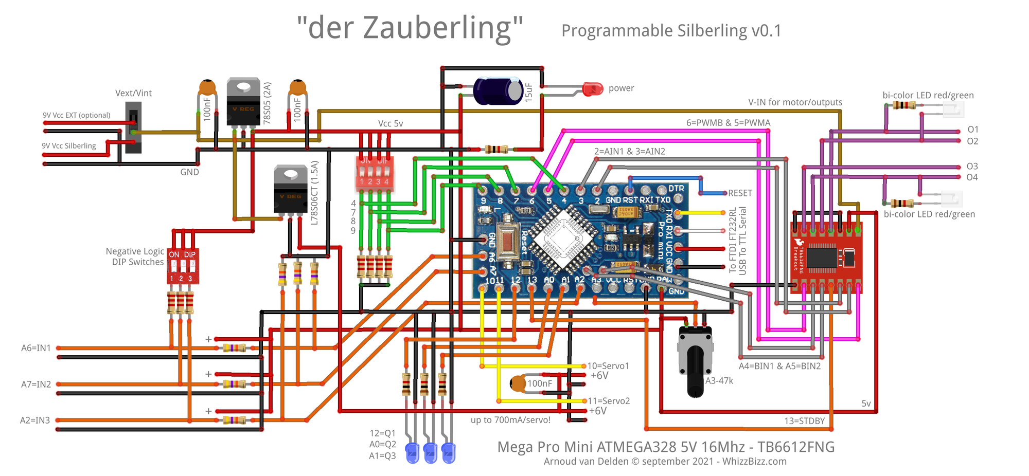
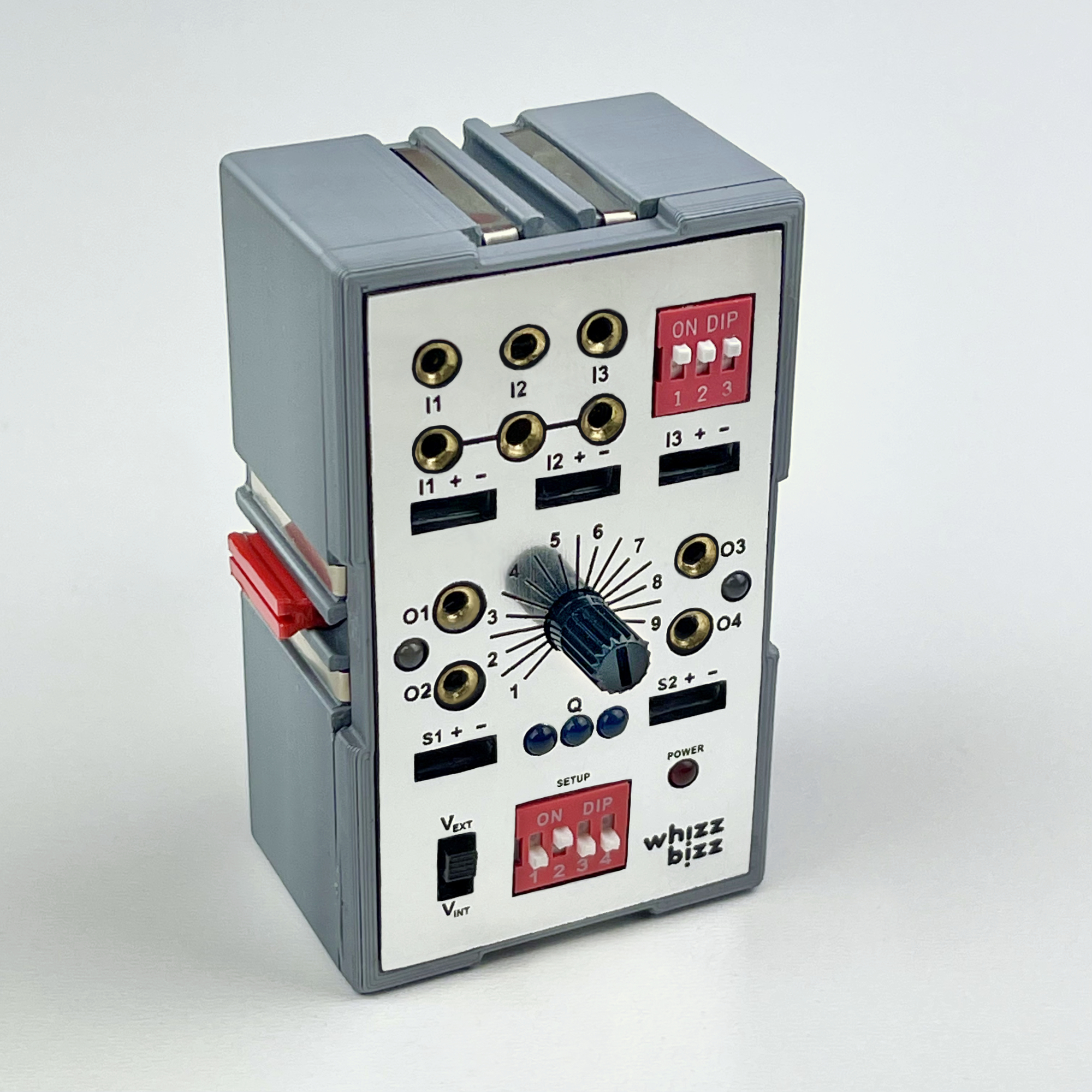
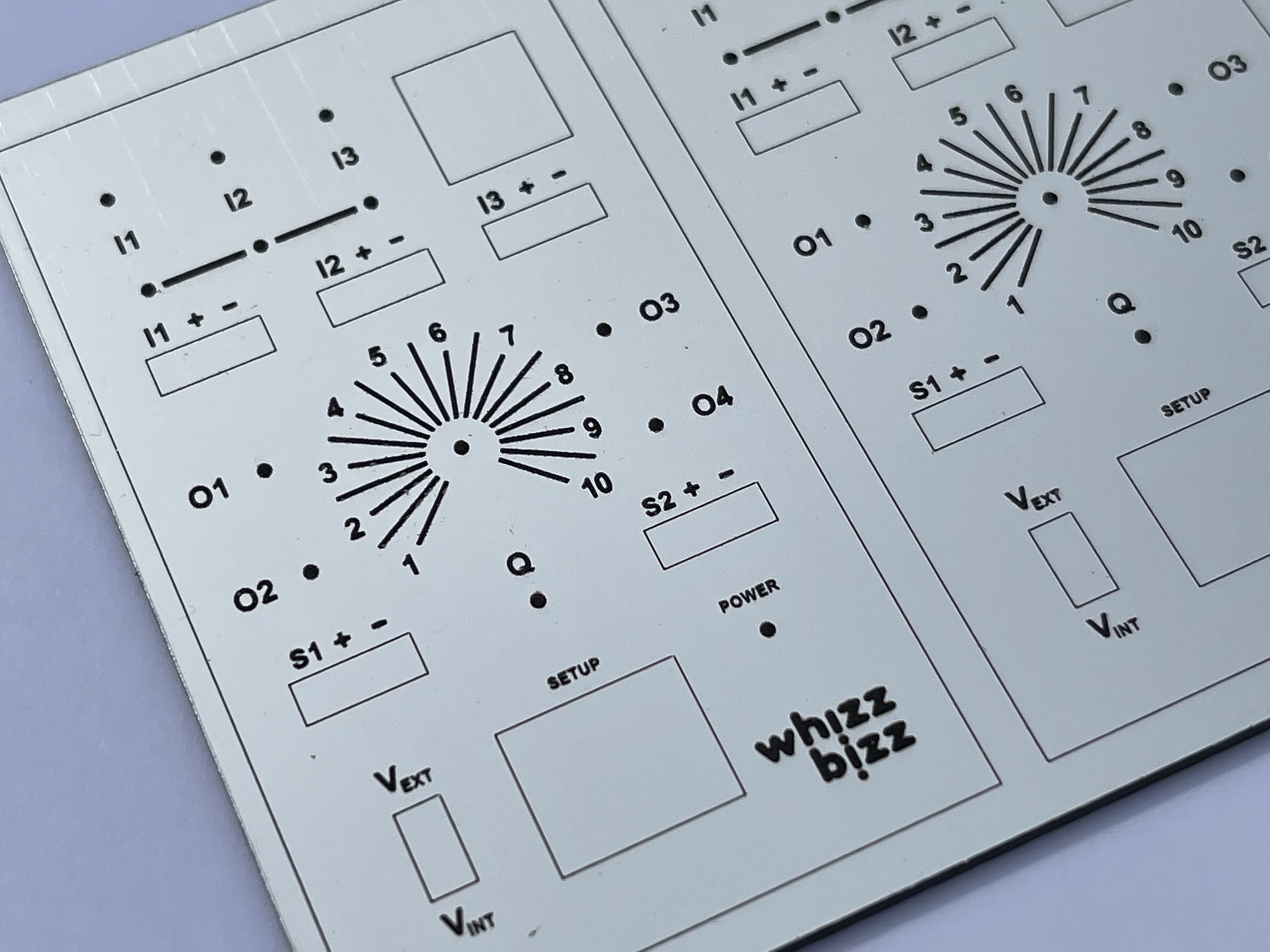
As can be seen in the wiring diagram, all inputs/outputs of the Atmega328P are used for the Zauberling! For the inputs, the switching analogy of the ftDuino and fischertechnik's own TXT controller has been followed, whereby the sensors at the inputs are switched to zero (ground/GND). This is more practical than with the E-Tec module, where the sensors are connected to +9 volts, so that active sensors with their own output voltage (usually 5 volts) cannot be used on the inputs due to the lack of a common ground.
The inputs are equipped with a voltage divider that protects up to input voltages up to 10 volts and makes it possible (with an external input voltage of 9 volts) to use the outputs as a digital or analog signal on the inputs. This makes it possible to combine with the traditional Silberlings.
By means of DIP slide switches, a bias voltage can be applied per input for passive sensors such as push buttons, reed switches, photo resistors or transistors, NTC resistors, etc. These sensors then lower the voltage on the relevant input, if their resistance is changes in the environment diminish. The Zauberling will therefore soon be able to handle both 'positive logic' and 'negative logic'.
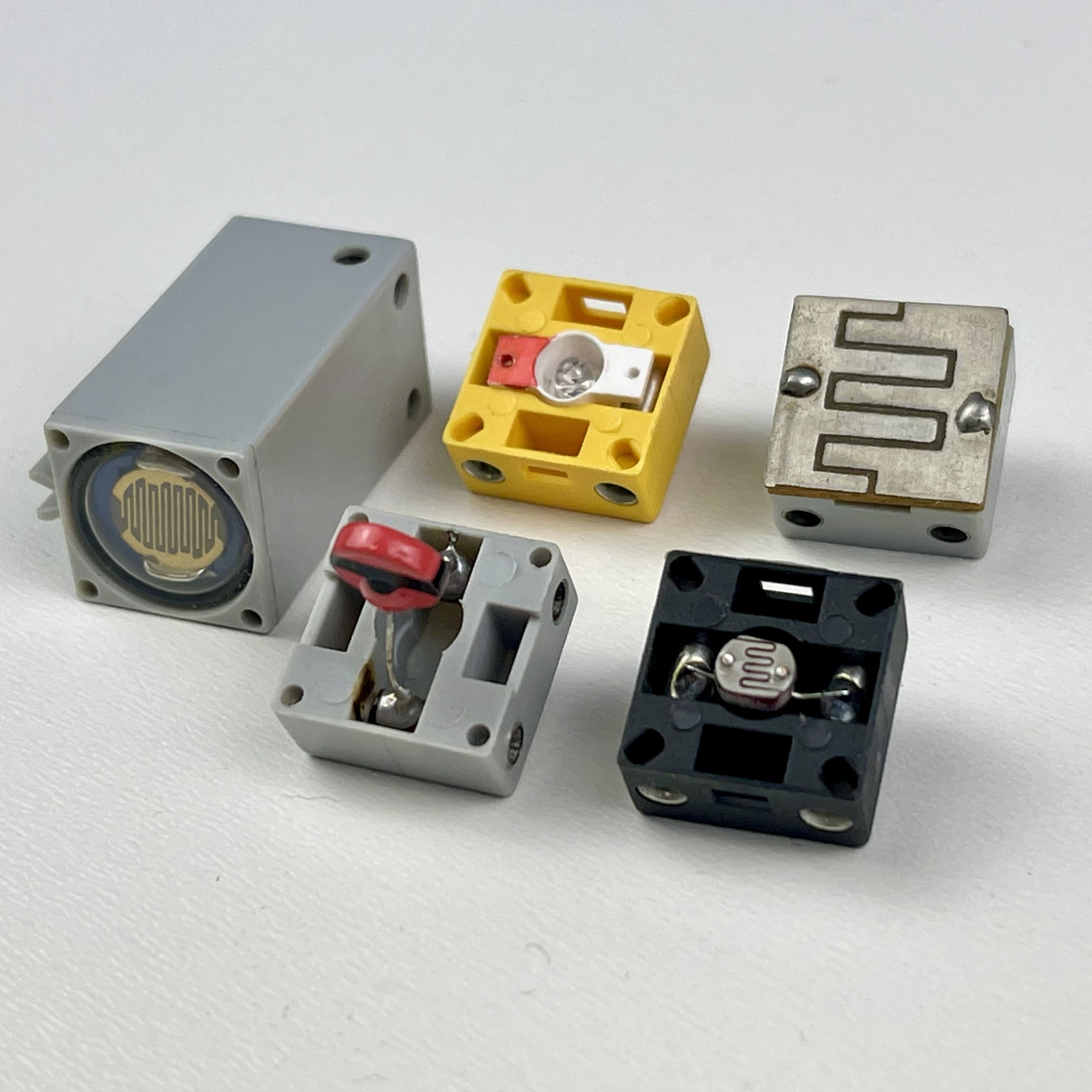
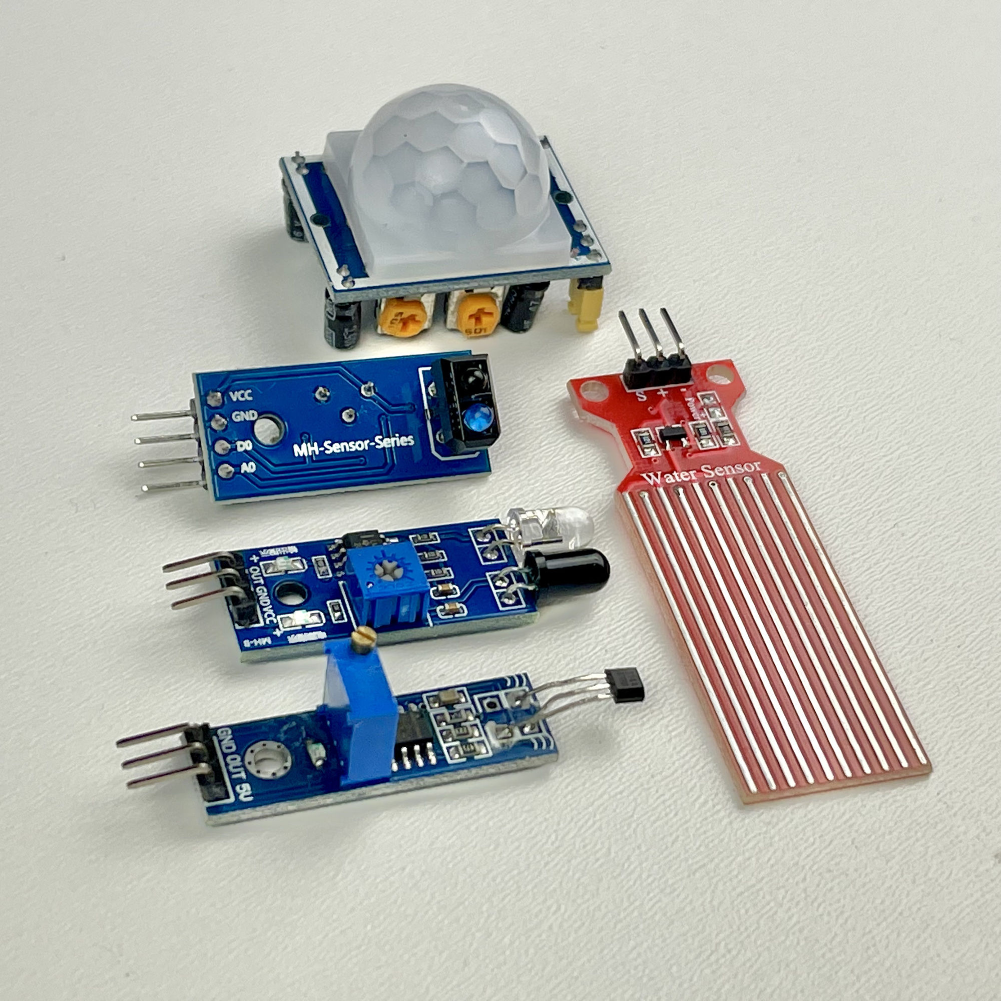
Various 'passive' and 'active' sensors
The interpretation and processing of the measured input voltages can be solved in software. As a result, the inputs could be kept relatively simple in terms of hardware. I have set the maximum input voltage of the (optional) external power supply at 9 volts for the time being. If it turns out in the future that an external voltage of 12 volts (or even more) is useful, it may be wise to protect the inputs with 5.1 volt zeners in a subsequent version.
Some classic Silberlings have a signal light with which the status of the output can be read. However, it is not immediately possible to read what exactly happens digitally at the inputs. However, the Zauberling also has feedback per input by means of a led. As a result, there is clarity at all times about the current status of the three inputs.
For connecting active sensors (such as hall effect, IR obstacle, PIR detector, etc), which are often designed as small modules, the necessary 5 volt power supply is carried on a three-pole connector. In addition, the well-known fischertechnik plugs can also be used on the prototype for the connections to the inputs.
How the detection thresholds of sensors on the inputs of the Zauberling can be 'self-learning', why no interference suppression is needed tp depress switching noise on the inputs or which programs are executed is all under control of the software. More on this in part 2 of this article.
As outputs, the dual outputs of a TB6612FNG motor-driver with PWM control are used. Each output of this small module can supply up to 2 Amps. I have already applied these driver modules in various projects and in practice they do not require their own heat sink.
Although this module demands a relatively large amount of the 20 inputs/outputs of the Atmega328P with seven control lines (two of which must be PWM). And if the motor output on O3-O4 always follows motor output O1-O2 inverted, we could save I/O lines on this. However, as configured now, we still retain full control over two independent motor outputs from the software. Although this is not necessary at the moment (for example in the 'Basic program'), it still offers the possibility to use the two motor outputs as four separate outputs in the future.
As can be seen in the schematic drawn with Fritzing, connections for two servos are also provided. The connectors have their own supply voltage of 6 volts for this.
DIP slide switches are read out for program selection, such as on the E-Tec module, for example. Serial reading of an (in principle unlimited) number of parallel selector switches requires a minimum of four data lines and one or more 74HC165 8-bit shift registers.
For program selection, the Zauberling has a DIP slide switch with four slide switches with which 16 different program choices can be made. For reading these settings, therefore, four parallel data lines were simply used, because serial reading of such slide switches only becomes worthwhile with wider DIP slide switches with more options (slide switches).
The rectifier building block h4 GB (no. 39570) could, according to the original specifications, deliver a maximum current of 800 mA. Apart from the fact that this maximum current is determined by the bridge cell used, it is limited in particular by the fischertechnik transformer used. The original fischertechnik transformers 812 and 814 deliver 5 VA and 7 VA (Watt) respectively. At the specified AC voltage of 6.8 Volts, that would mean a maximum current of (5/220=) 735mA and (7/220=) ~1A respectively, although fischertechnik, probably for safety's sake, only specifies 0.5 Amps at the AC output.
In practice, several only digitally used (< 800 mA) Zauberlingen should be able to be supplied from the traditional power supply of the Silberlings with the rectifier module h4 GB (No. 39570). According to fischertechnik's own specifications, the transformer delivers an alternating voltage of 6.8 volts, which leads to a rectified voltage of ~9 volts. However, the fischertechnik transformers date from the beginning of the second half of the 20th century, when the mains voltage (in the Netherlands) was still 220 volts. The goal is now 230 volts, although in practice here at home (in various samples) the actual value often turns out to be between these two extremes. This could of course differ regionally or nationally.
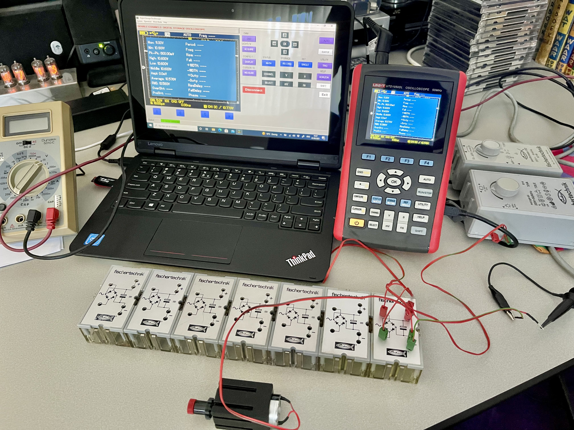
Based on experiences and (recent) publications from fischertechnik colleagues, I decided to take a look at the output voltage on the oscilloscope. It was confirmed that the transformer outputs of the 812 and 814 transformers I tested (without load) showed an alternating voltage with peaks of up to 12.8 volts. Fortunately, the RMS value (energy content) was closer to the specified value of 6.8 volts at about 8.7 volts. The h4 GB rectifier modules here generate (without load) an average DC current of about 11 volts, of which under load (for example with a small fischertechik motor) it decreases to about 10 volts.
It is clear that the option of connecting an external 9 volt power supply is very nice. Especially if several motors or other consumers, such as solenoid valves for a pneumatic model, have to be controlled. Ideally, the module should therefore have its own 5 volt voltage regulation for the microcontroller and powering active sensors and the servos. But it was difficult to determine how much heat would be produced and whether, for example, the servos (which can draw up to 650 mA under load) need their own 6-volt supply. That's why I first built the circuit experimentally.
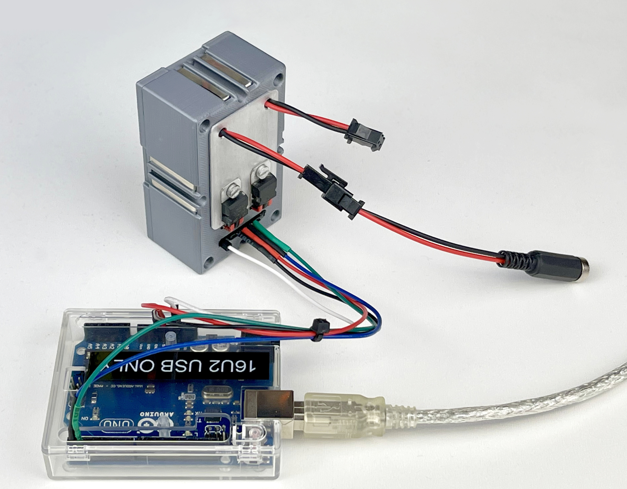
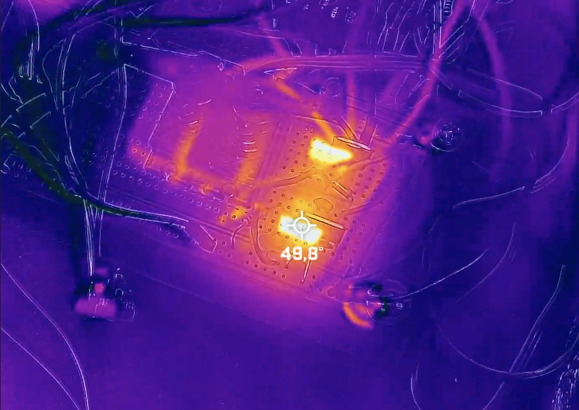
The experiments showed that the basic circuit of the Zauberling draws only 66 mA when idle. When testing the motor outputs, peaks of 400 mA were measured. A single 7805 voltage regulator can supply a maximum of 1 Ampere and immediately became quite hot. I replaced it with a 7805CV that can deliver a maximum of 1.5 A.
When testing with the two servos, the heat development continued to increase. One moving and mildly loaded MG90S mini servo drew up to 425mA in the test set-up. According to the specifications, this can easily go up to 650 mA under a heavier load. This means that while the use of two servos at the same time is possible for a short time, it is wiser to give the servos their own 87S06 voltage regulator for 6 volts and to use an even heavier 87S05 (maximum 2 A) for the 5 volt supply. Not so much because of the amperage, but because some oversizing never hurts. In addition, this test showed that it makes sense to mount both voltage regulators on a cooling element to be on the safe side.
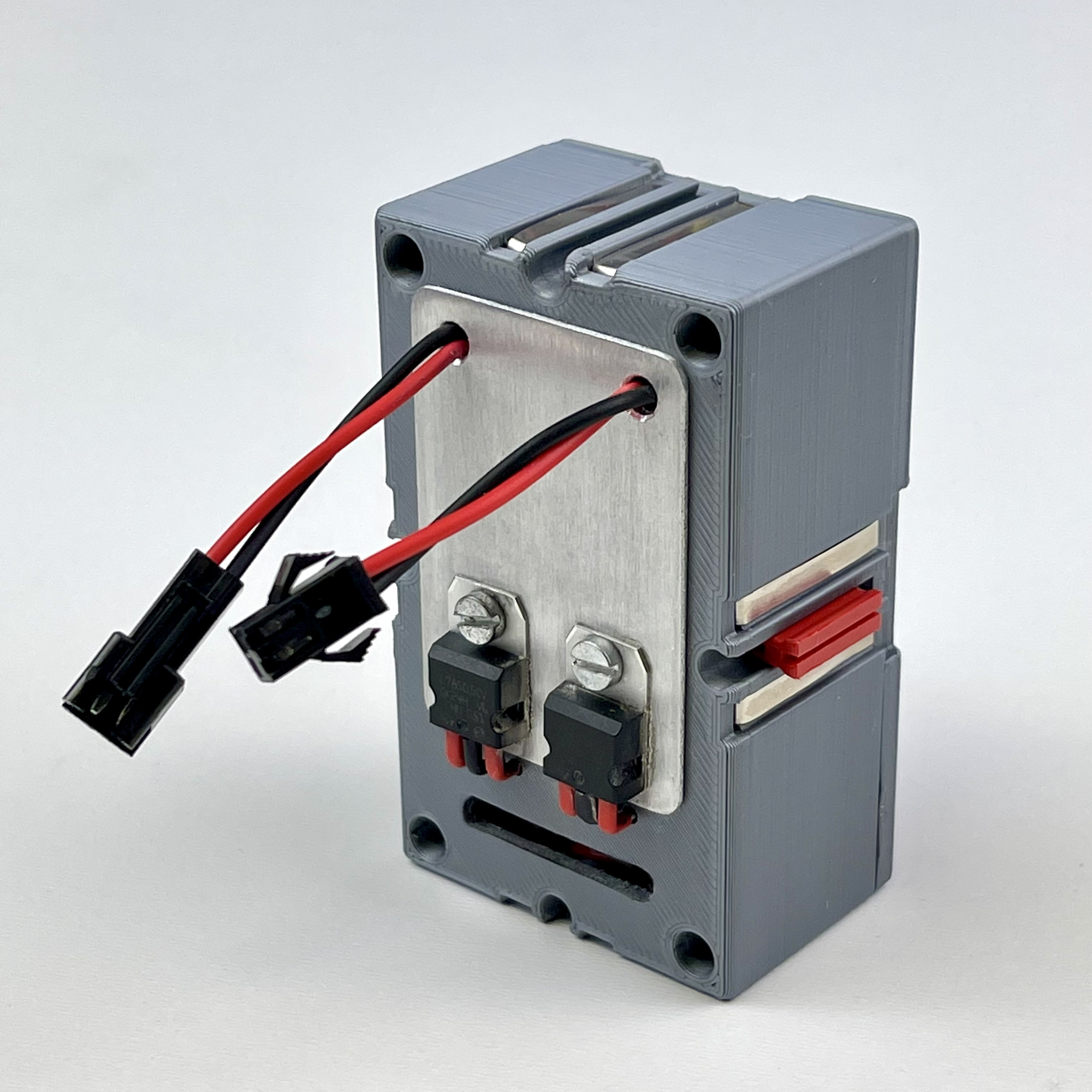
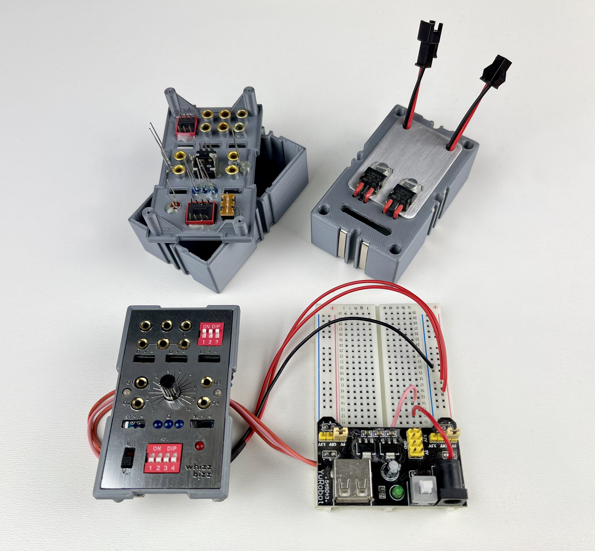
Eventually I decided to make the modules loopable and to give the voltage regulators a small cooling element on the back of the Silberling in the form of a piece of aluminum plate. This is fine for this prototype, version 0.1. For a next version, a separate power supply board at the bottom of the housing may be considered, which also directly houses the connections for the external power supply. This would make installation easier. In addition, the connectors for any possible looping through of the power supply can then also find a place directly, so that no loose cables with plugs, sometimes unused, are needed for this.
Assembling and testing the prototype was a precise job, but there were no significant setbacks. The wire spaghetti of the experimental test set-up had now become a Zauberling. When screwing it shut I got the feeling that I was locking the genie in the lamp... 🙂
The Zauberling worked almost immediately as it had already shown on the breadboard. The small cooling element on the back is excellent for this. Even at full load it didn't get more than lukewarm.
It might be worth considering building the Zauberling more in SMD technology in the future. After all, both the microprocessor and the motor driver are already implemented in SMD technology. This is certainly worth considering for the TB6612FNG, the complete module I used has hardly any additional components. On the other hand, the individual chips are probably just as expensive in practice as the complete modules. These also have the advantage that they can be mounted 'piggy-back' on the main PCB, which simplifies the design and makes more economical use of the (vertical) space.
So far I have not needed the servo outputs. These do seem useful, but perhaps a separate servo-Silberling with more manual setting options per servo could be considered for this in the future. Another consideration is whether the next version should still have sockets for the traditional fischertechnik plugs. In addition to making it easier to carry power supply for active sensors, the more modern pin connectors use the spare space on the front of the Zauberling a lot more efficiently. And also: In principle, the trusted fischertechnik plugs only need to be in the model on the side of the controlled fischertechnik components.
What will certainly get a place on the front in the future is a reset button. In practice I already noticed that this can be very easy, for example after making program changes with the DIP slide switches. For now I solved this by including a micro-switch in the wiring from the Uno I use for programming. It is also possible to briefly move the Vext/Vint slider to the neutral center position and thus force a reset.
The Zauberling now has his (first) magic wand. But what is a mage without his magic spells? In part 2 of this series we therefore look at the (first) software for this DIY Silberling.