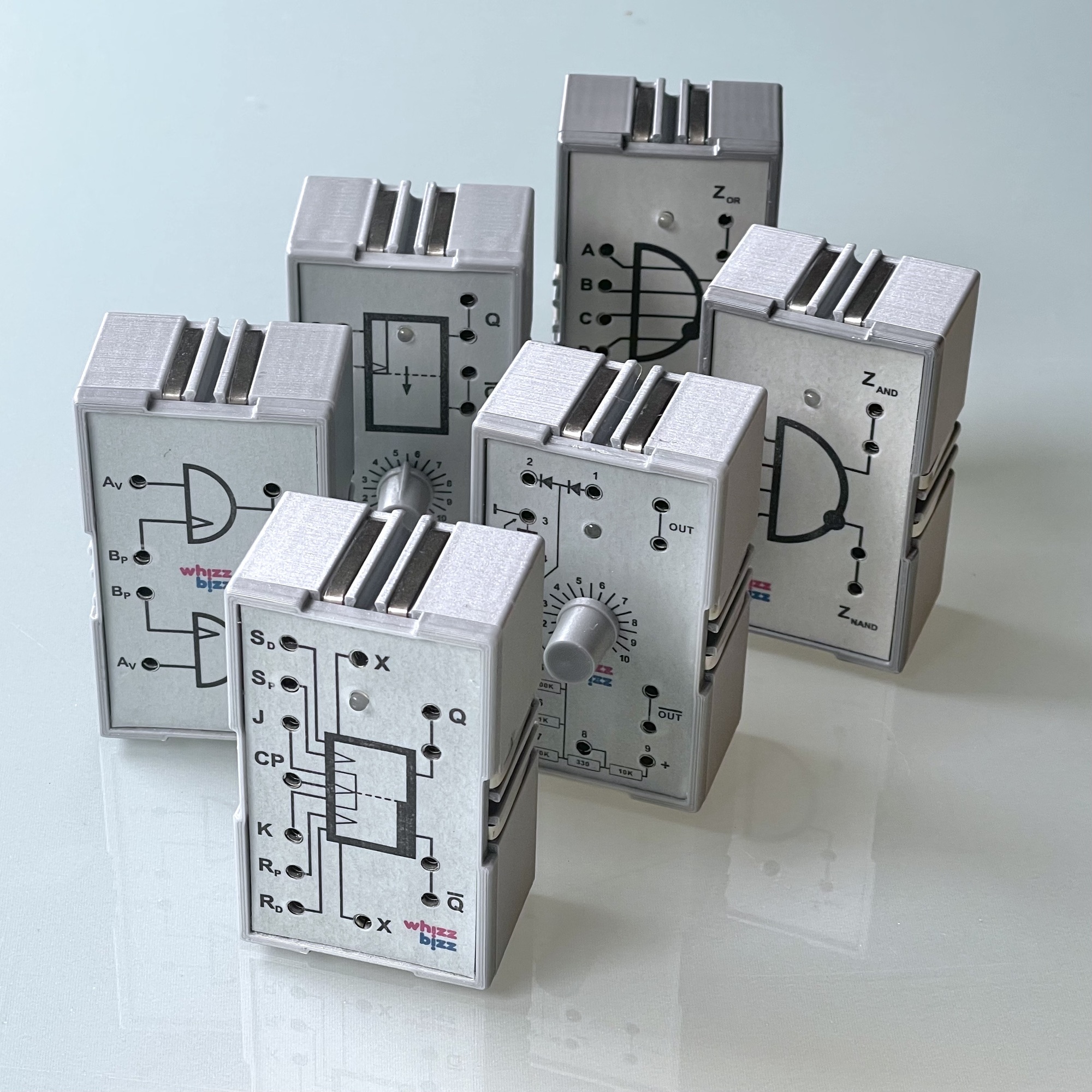
In my own “reproductions” of these modules, I wanted to stay as close to the original as possible. For example, I also wanted to be able to connect the power supply of the modules in the same way as with the original ‘Silberlingen’. Metal clips are pushed between the modules for this purpose. By now, many modules had been built and the question was asked more and more regularly whether these functional replicas were not for sale somewhere.
Meanwhile, ready-built and tested modules are listed in the online catalog. However, for those who have some knitting skills, and can solder a little, even more affordable building kits are now available.
The building instructions for these kits can be found on this page. Since the various modules differ little in construction and parts used, one common description suffices. There is also an instruction video that clearly shows the few possibly difficult issues (such as attaching the metal strips to the sides of the housing, or soldering a potentiometer to the board).
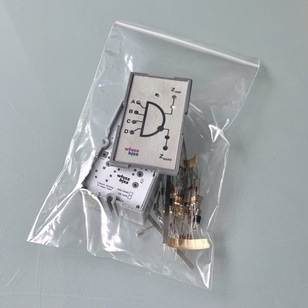
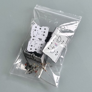
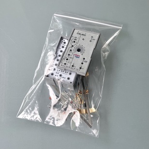
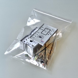
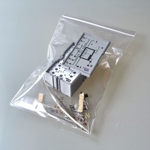
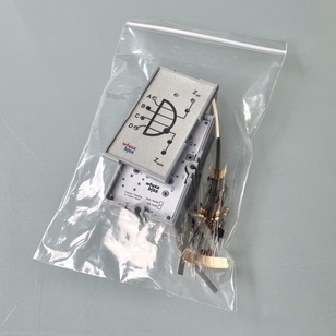
In the “Silberling” construction kit are the housing with cover and front plate of the chosen module. Also included are a circuit board and all parts required for construction. The schematic of the module and a sketch of the component arrangement can be downloaded below as a PDF document. The assembly instructions are in Dutch, English and German.
Tip: It is convenient to deposit the contents of the bag in a container
That way everything can be found quickly in a moment and no components get lost
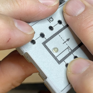
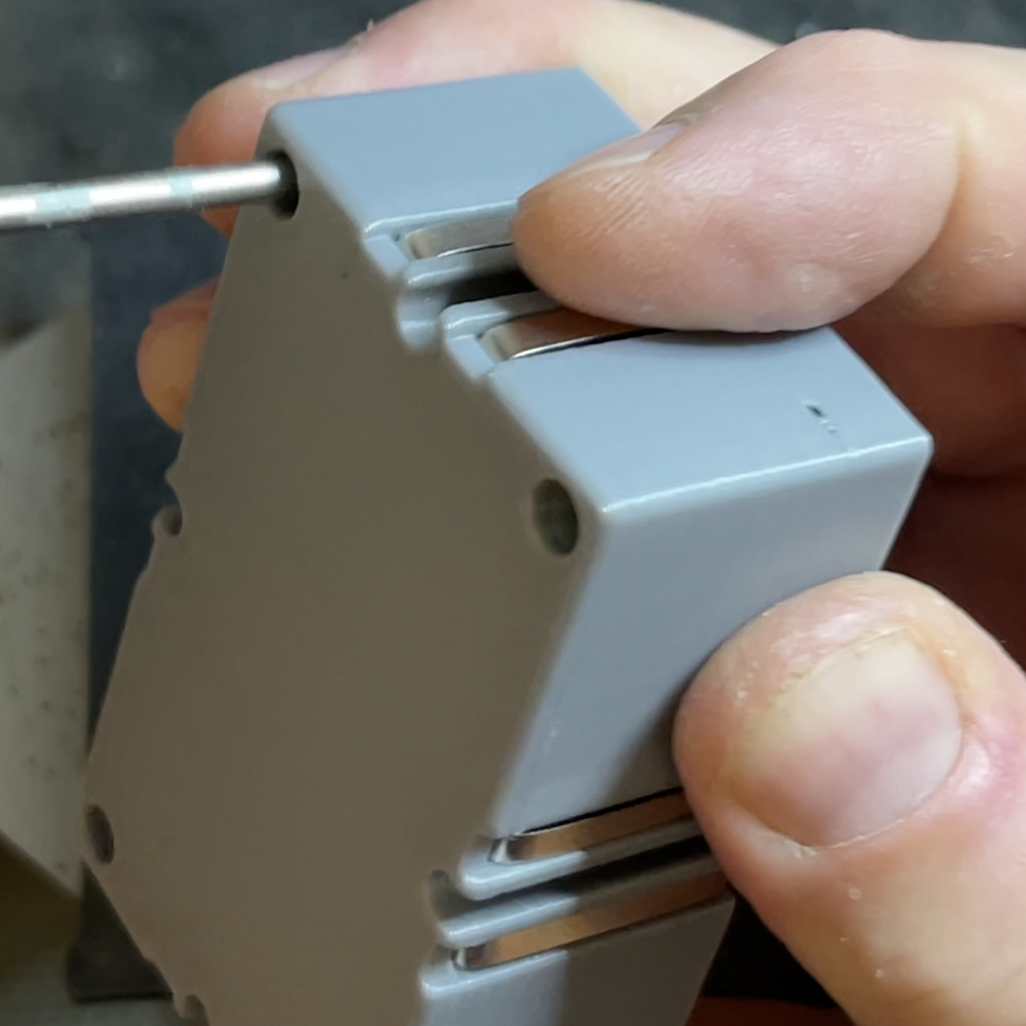
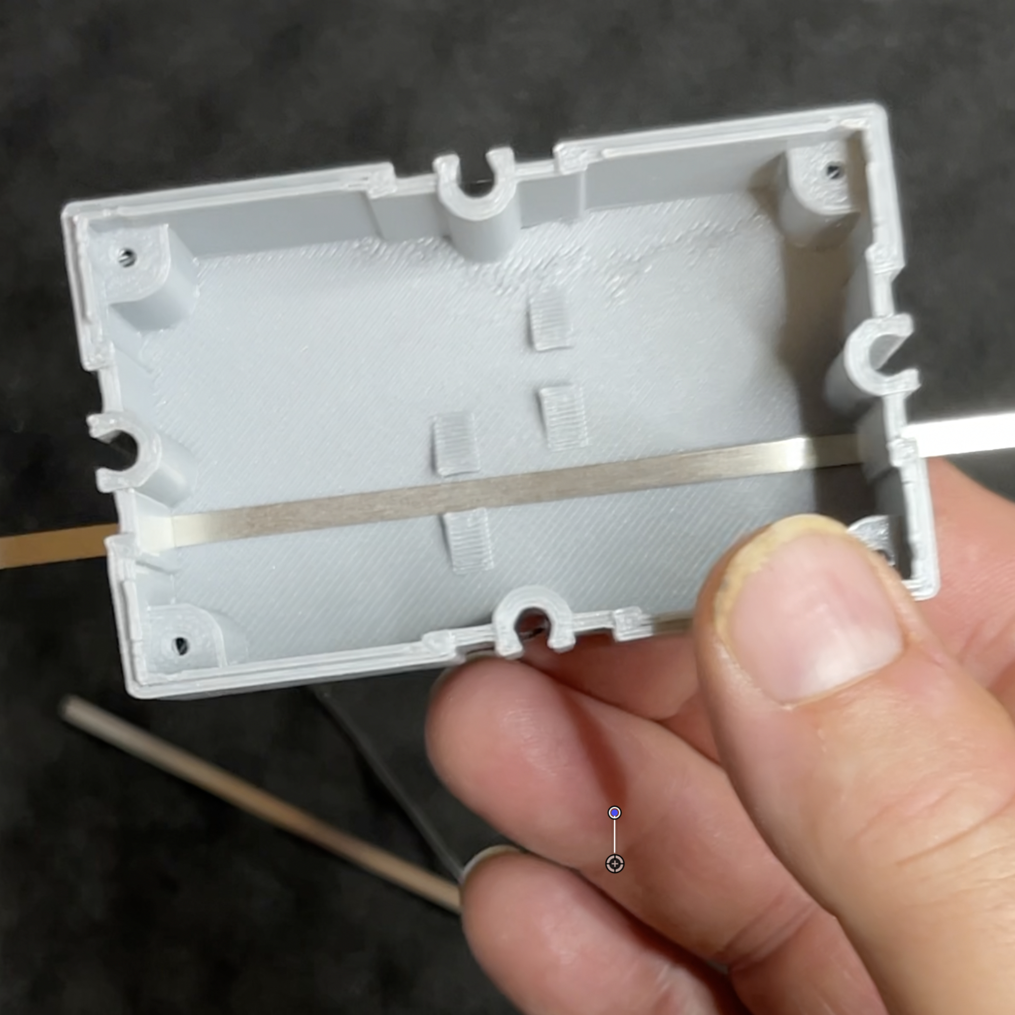
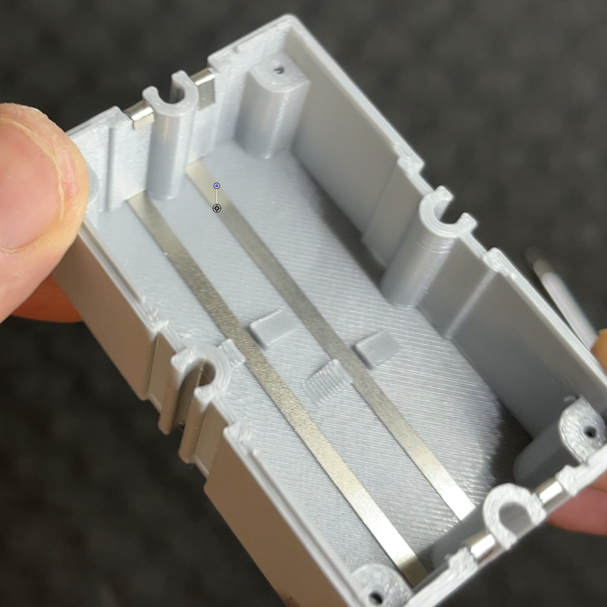
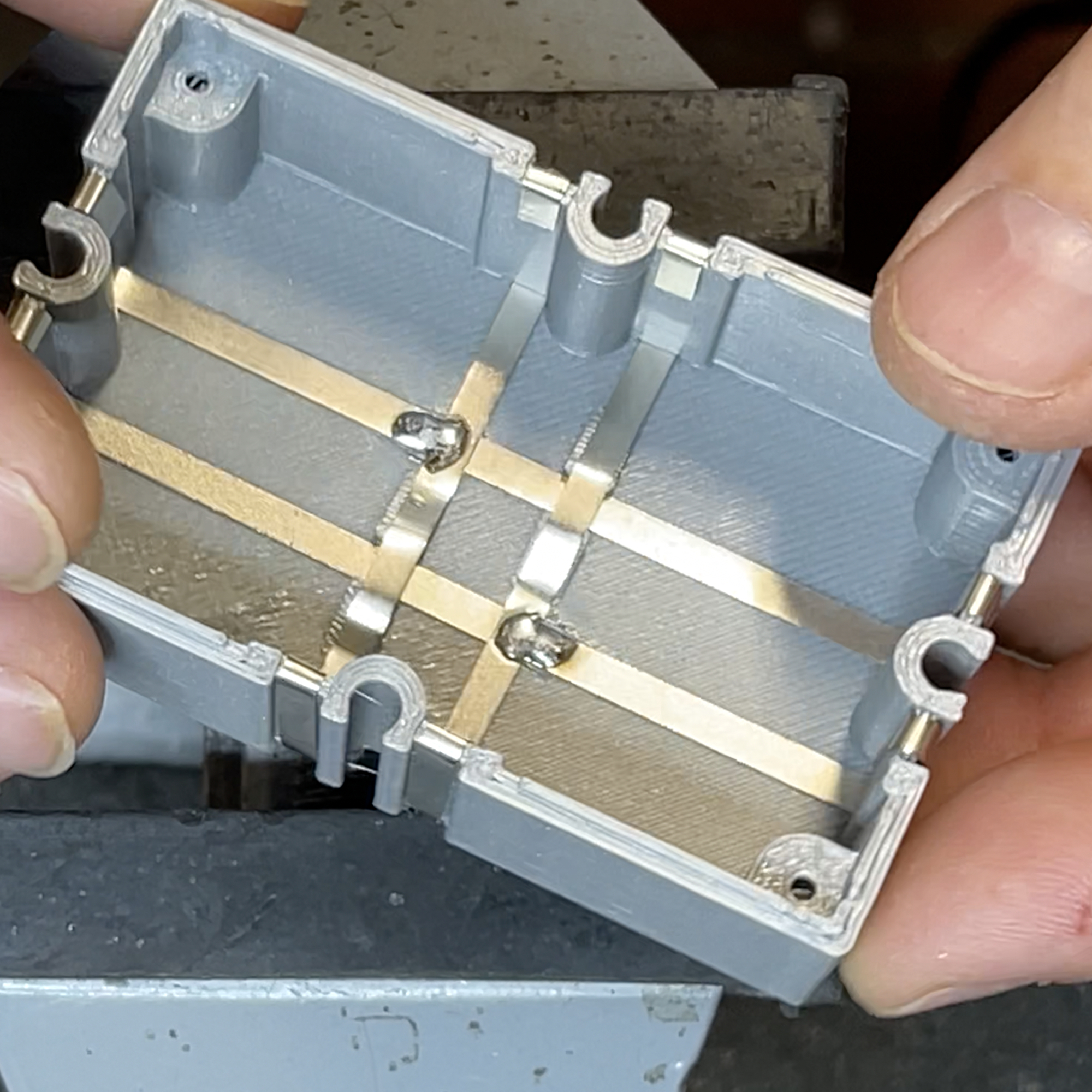
The package contains two short (~10 cm) and two longer (~13 cm) metal strips. These will form the power supply connections in a moment. They are applied to the sides of the 3D printed module case.
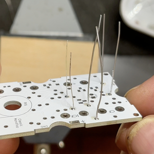
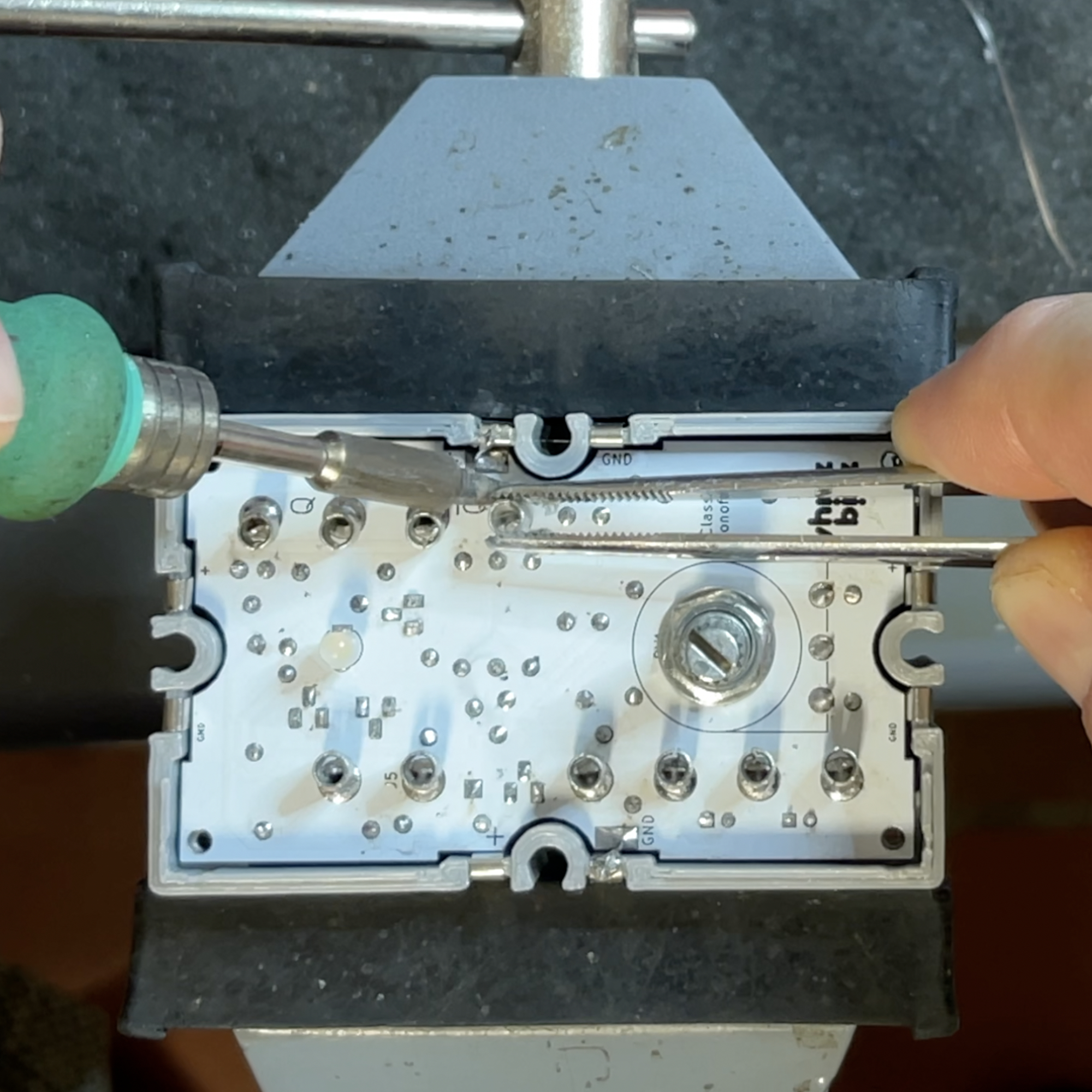
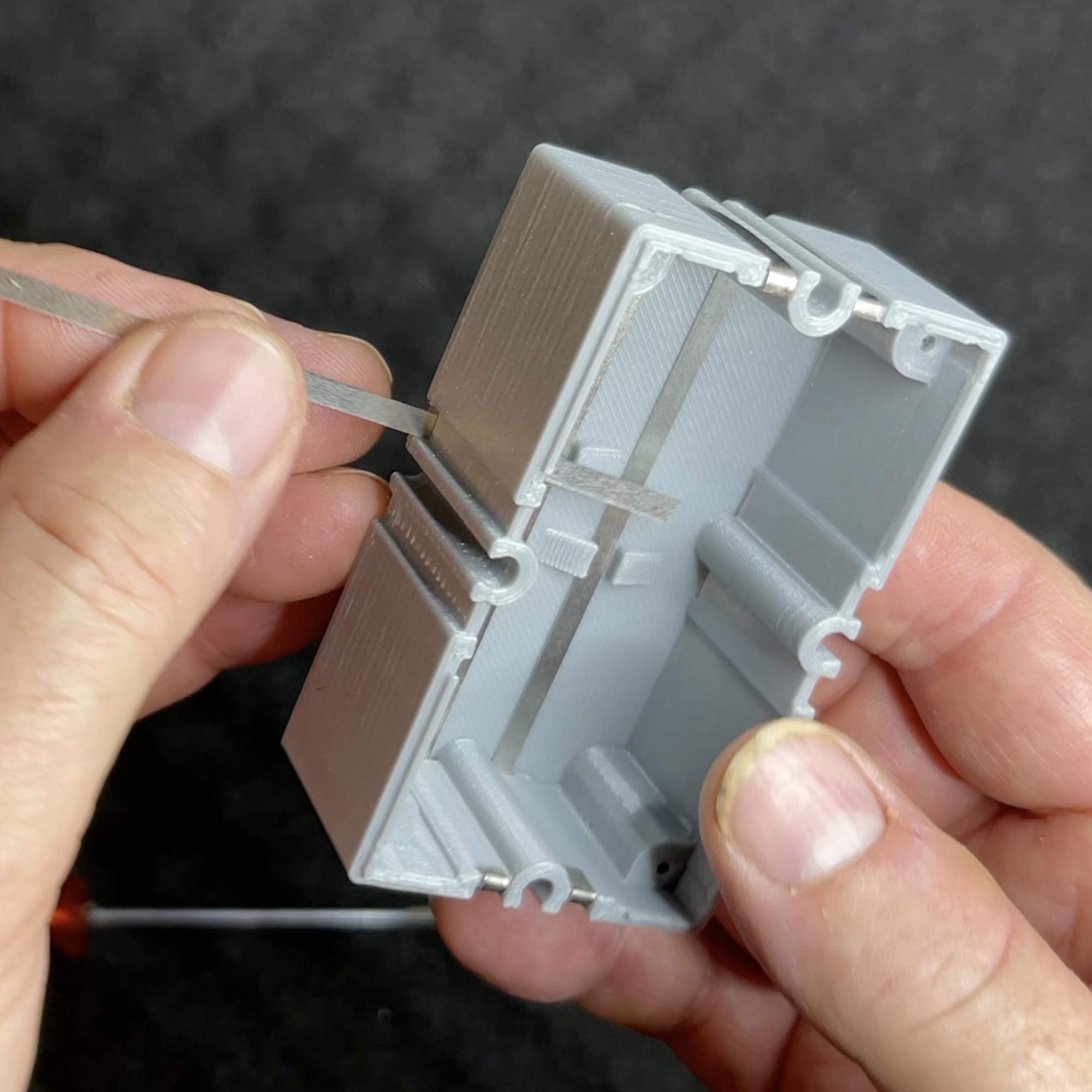
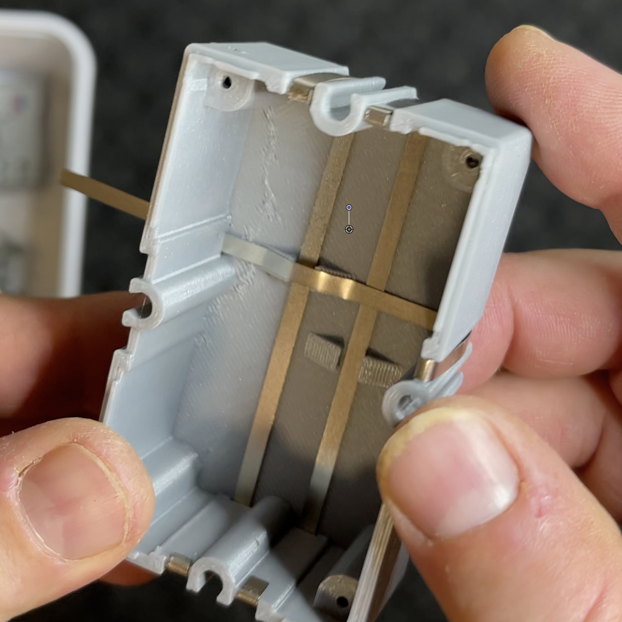
Start with the two longer strips. These run vertically, on the bottom through the opening of the two "bridges. Each metal strip is pushed through a small slot on the short side of the case. Let the strip extend the same length on both sides (illustration). You can easily check whether the length on both sides is (approximately) the same with a screwdriver. Now bend up the protruding ends and fold them back inward, over the wall of the housing. Repeat with the other long metal strip.
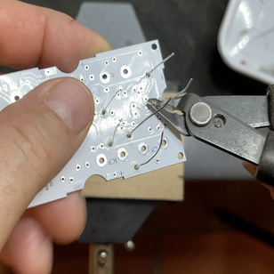
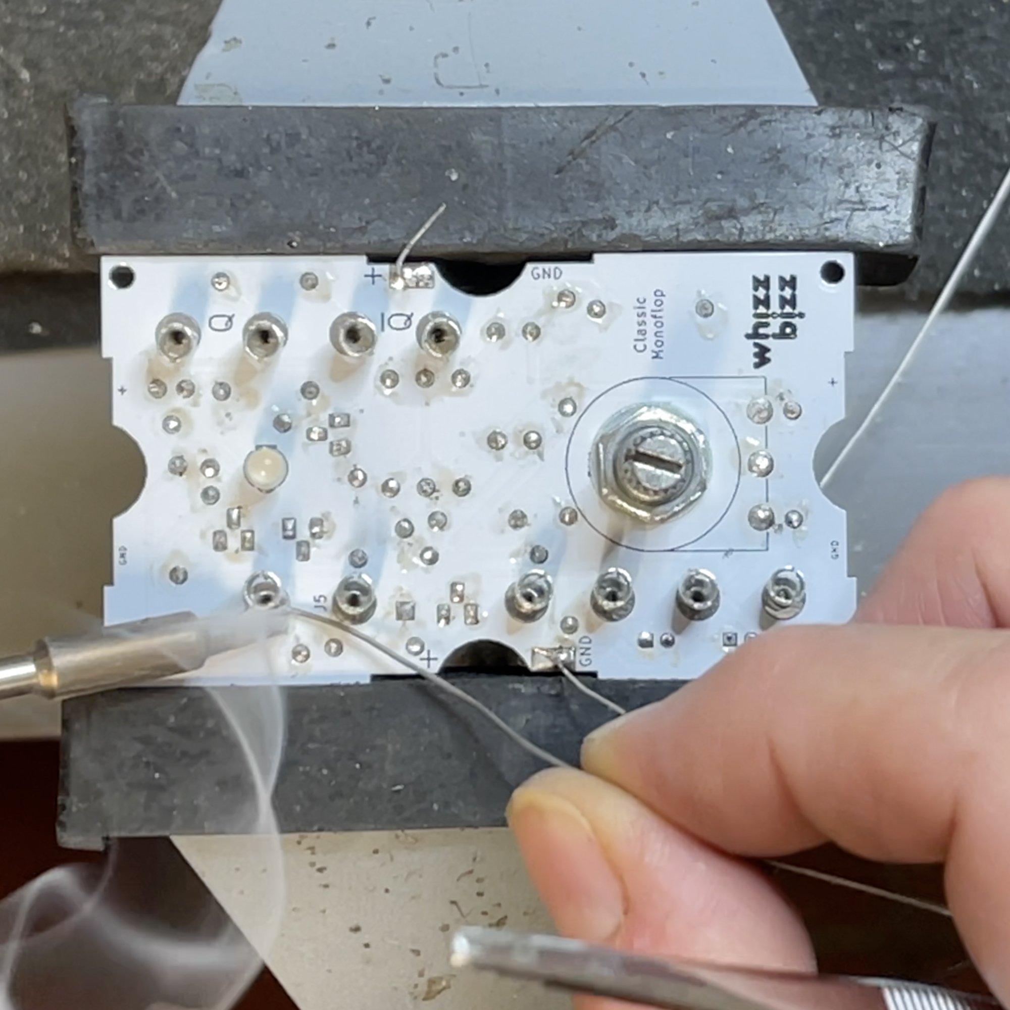
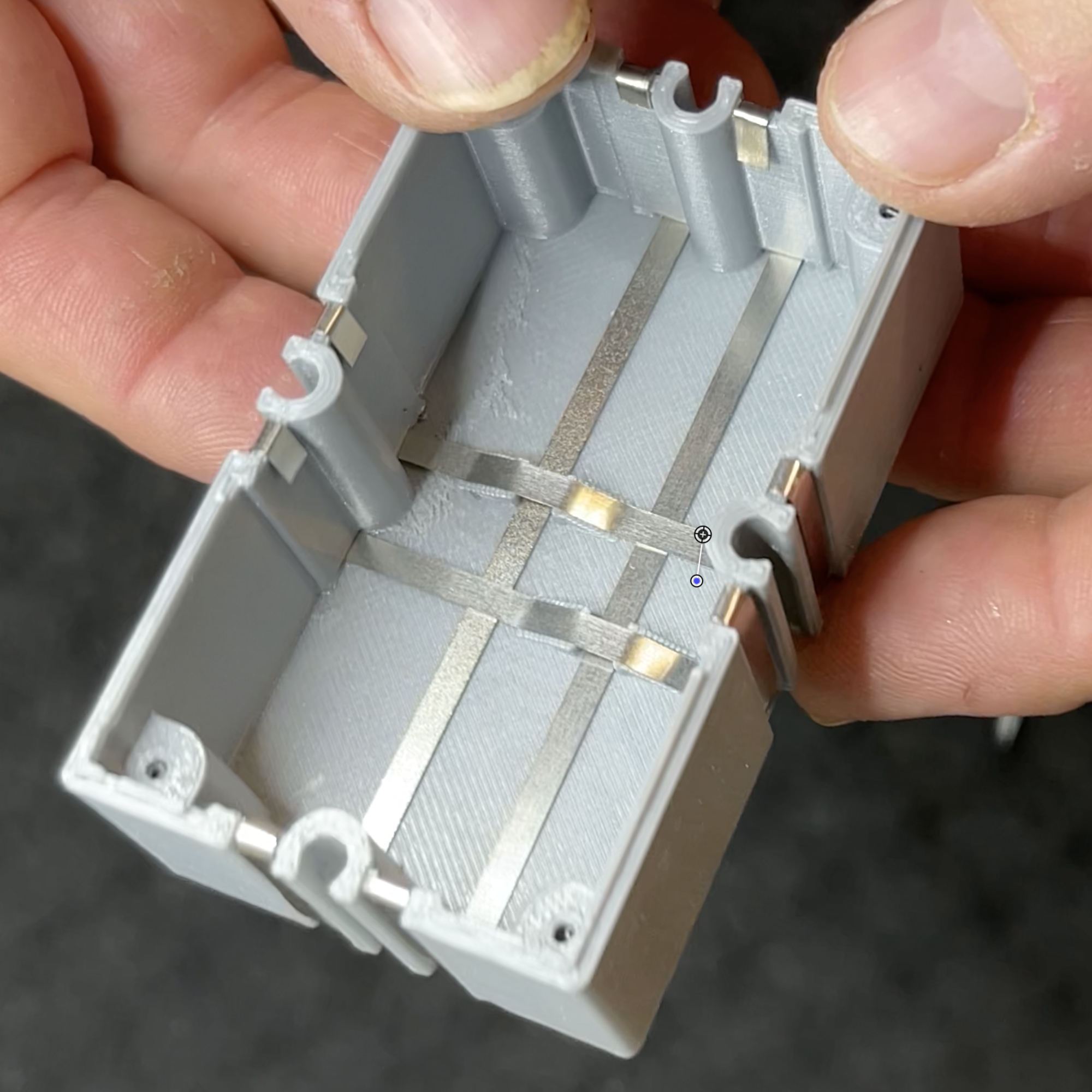
The intersections of the metal strips on the bottom of the case should be soldered. Be careful not to overheat the strips in the process, as this may melt and deform the plastic of the back of the case.
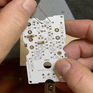
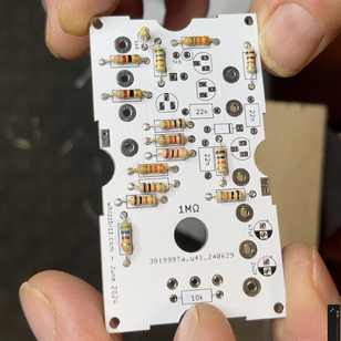
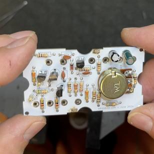
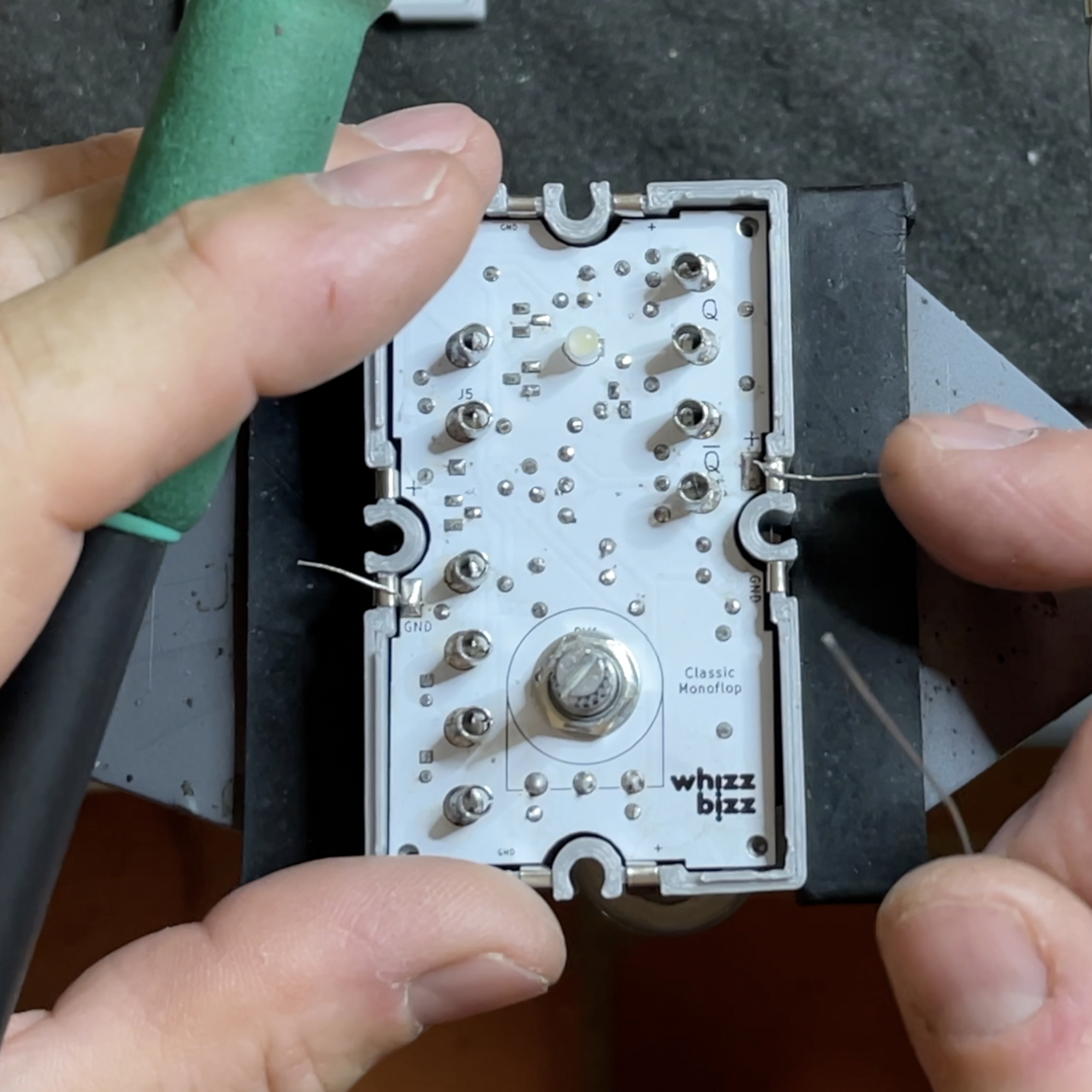
Follow the component layout to solder the various components on the board. Do the low, lying down, components (resistors and diodes) first. Then the electrolytics and transistors and any resistors to be “standing”. Save some of the cut-off wires to mount the potentiometer (rotary knob, as on the Monoflop and ‘Grundbaustein’). Two wire ends are also needed to solder the circuit board to the metal strips in the housing.
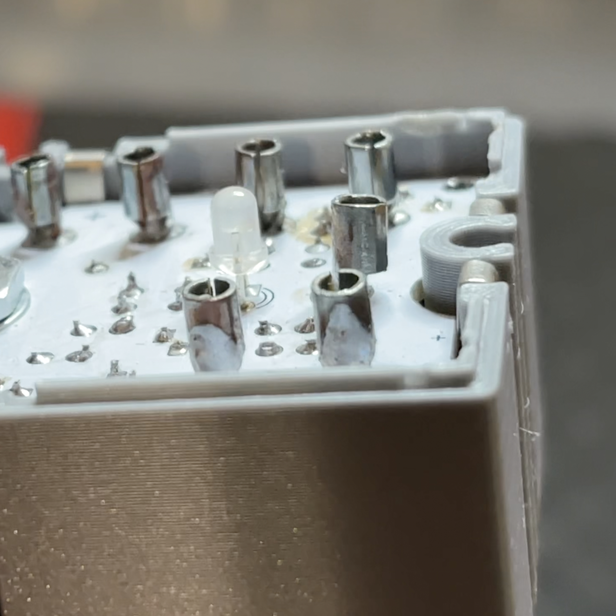
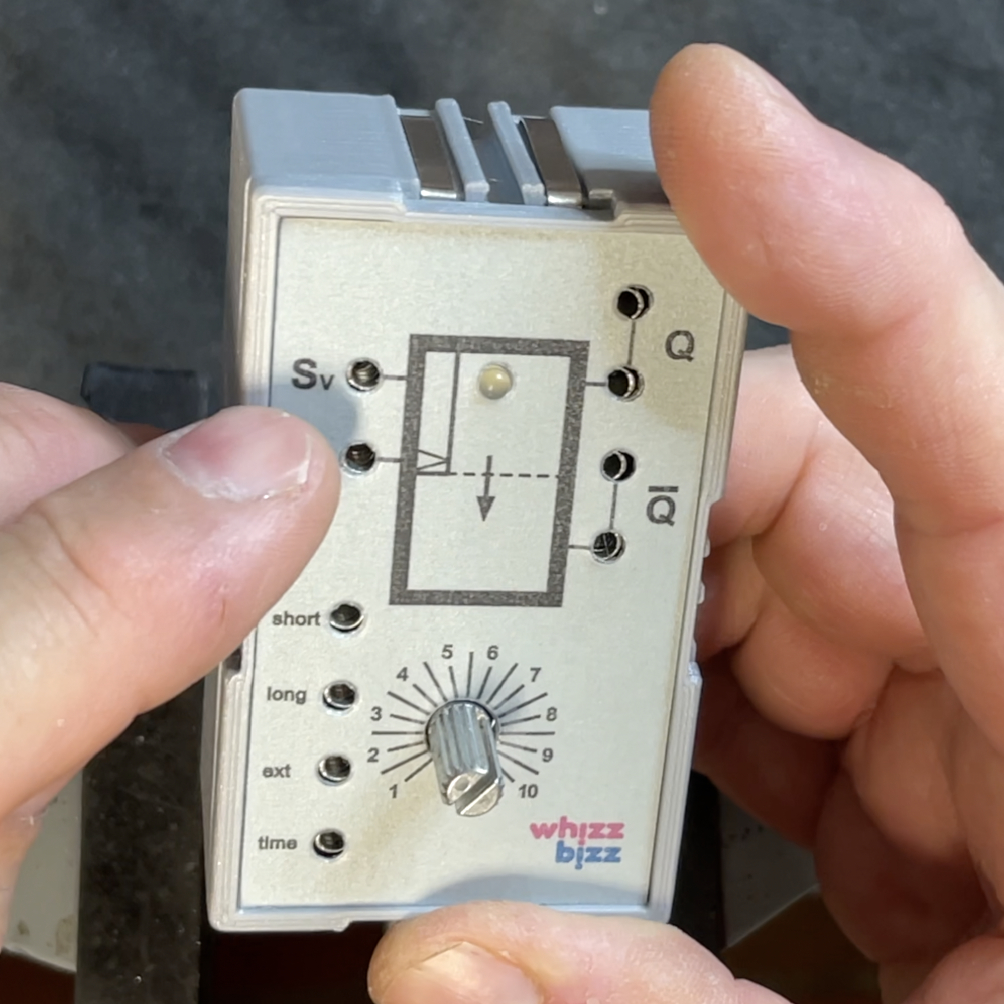
The LED is mounted on the other side of the circuit board (front side). Note the polarity: the square island on the circuit board indicates the minus (cathode). The LED has a shorter mounting wire on this side. Also, the collar the LED has a straight plane on this side. Push the LED at the top of the circuit board through the holes, temporarily place the faceplate on top and push the LED from behind well through the hole in the faceplate. Turn this assembly over and solder the LED on the component side of the PCB. This will mount the LED high enough so that it sticks well through the hole in the front panel.