
On the last club day of the Dutch fischertechnik club, a competition was held for autonomous driving cars. These so-called ‘Robocars’ had to be able to complete a course independently, the track of which was marked by a black line. In this article, I describe my experiments with a Robocar equipped with a camera with its own line recognition logic: the Pixy2 camera.
This camera can recognize the track. The recognized vectors can be read via the I2C bus and can be used via a so-called PID control to steer the car along the course.
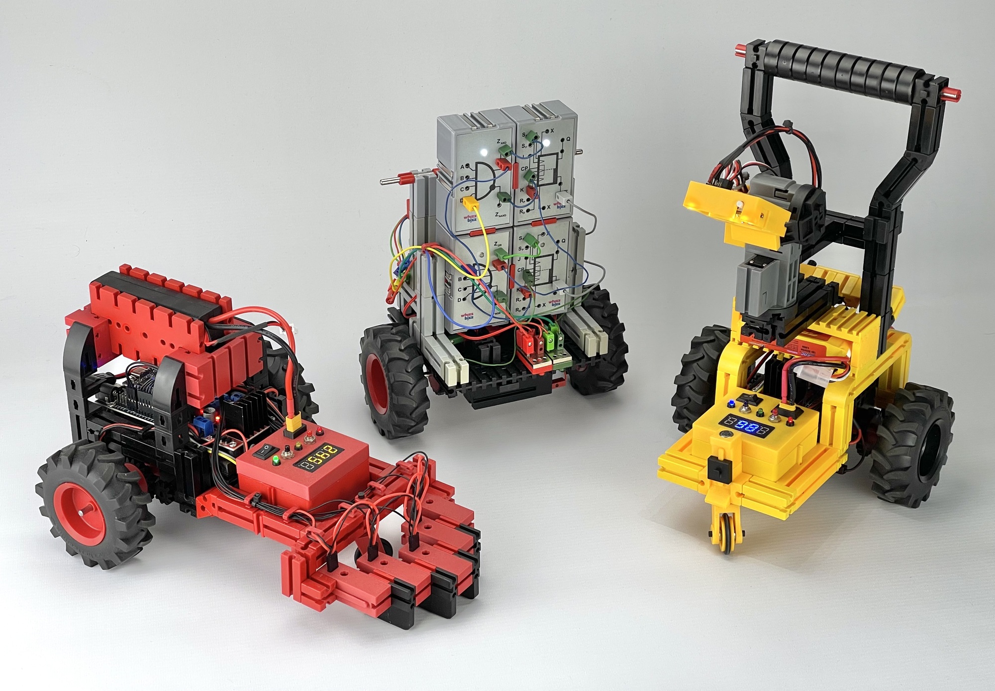
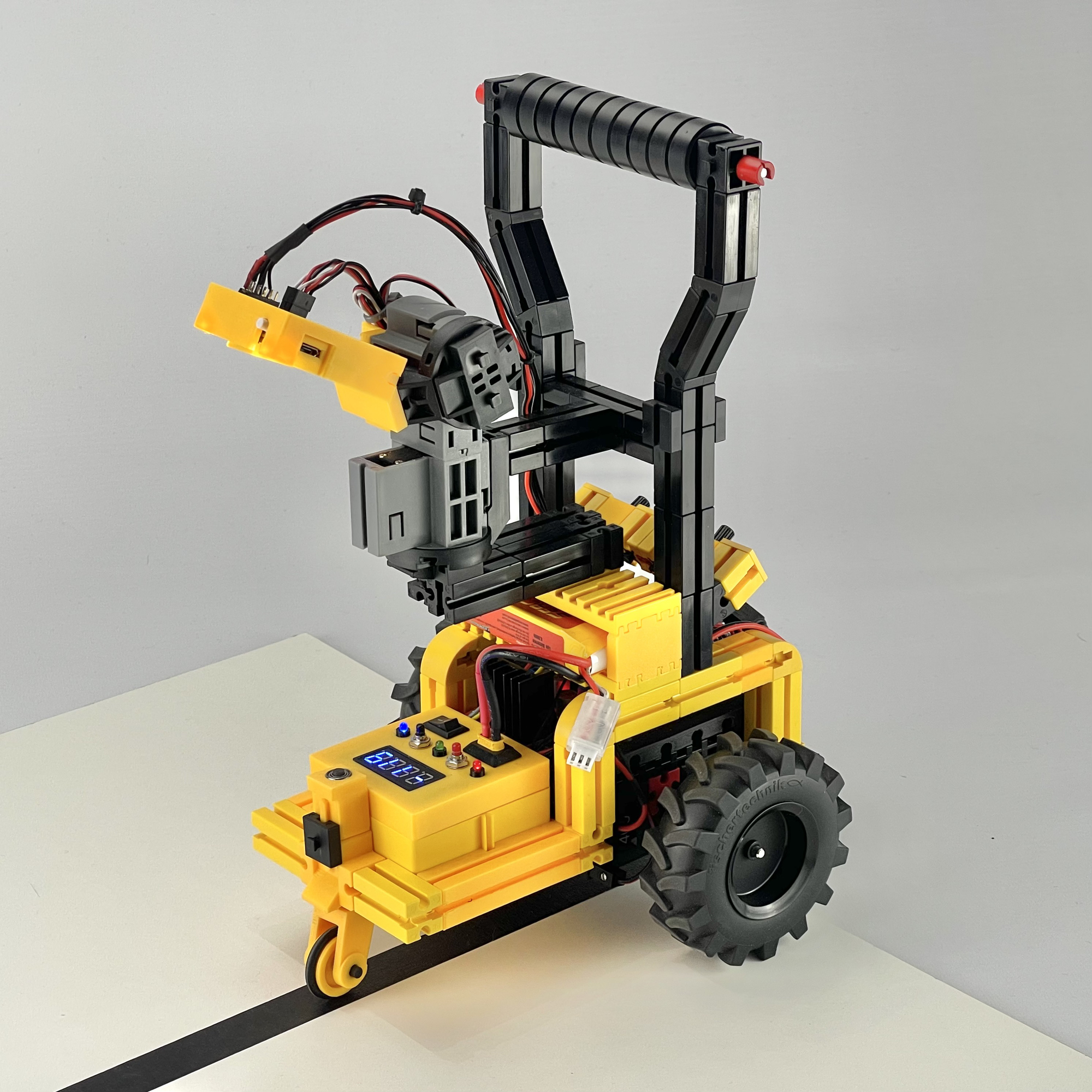
I took advantage of participating in this club competition to build various vehicles with different line-following techniques. With the cars equipped with a microcontroller, I was able to experiment with PID motor control in the software to make the car respond as smoothly and quickly as possible to turns. I also tried an algorithm with more than the usual two infrared line sensors. This car finds its way smoothly and quickly with five IR sensors! I also made a car with a line recognition camera. First, I will discuss the yellow Robocar with I2C camera on the far right in the photo below; I will describe the other two in the future.
The course on club day had no intersections or junctions, but it did present a challenge in the form of a ‘roundabout’. It is understandable that many vehicles got confused here: in most cases, as with the well-known fischertechnik construction models, only two sensors are used to detect when the car leaves the line and needs to steer. This makes it important to steer as quickly as possible as soon as the first sensor leaves the line.
If a microcontroller, such as the TXT controller, can be used, it is only important which sensor left the line first. The software control can then try to find the line again, even if both sensors have left the line in the meantime. Without a microcontroller with software control, it is best to avoid both sensors leaving the line. In practice, however, this means that the speed cannot be increased too much. But even if a more intelligent control system can be created with a microcontroller, there remains a delicate interplay between the maximum speed and the weight (and therefore the inertia) when steering. The distance of the sensors from the pivot point of the cart must also not be too great to prevent the line from being left.
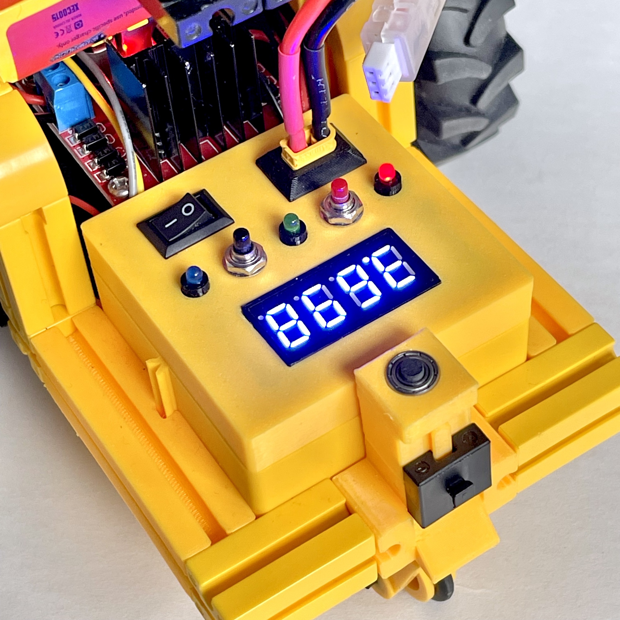
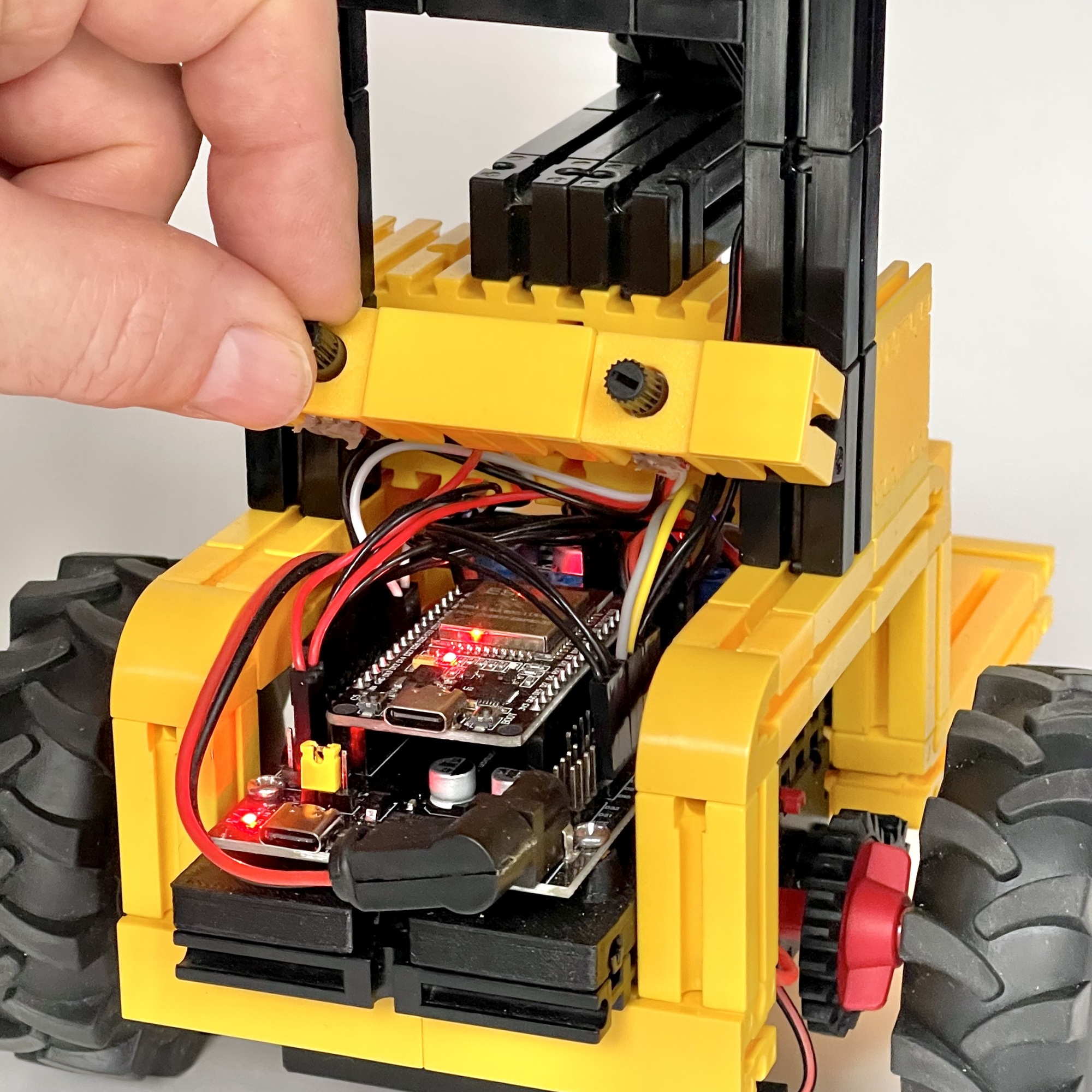
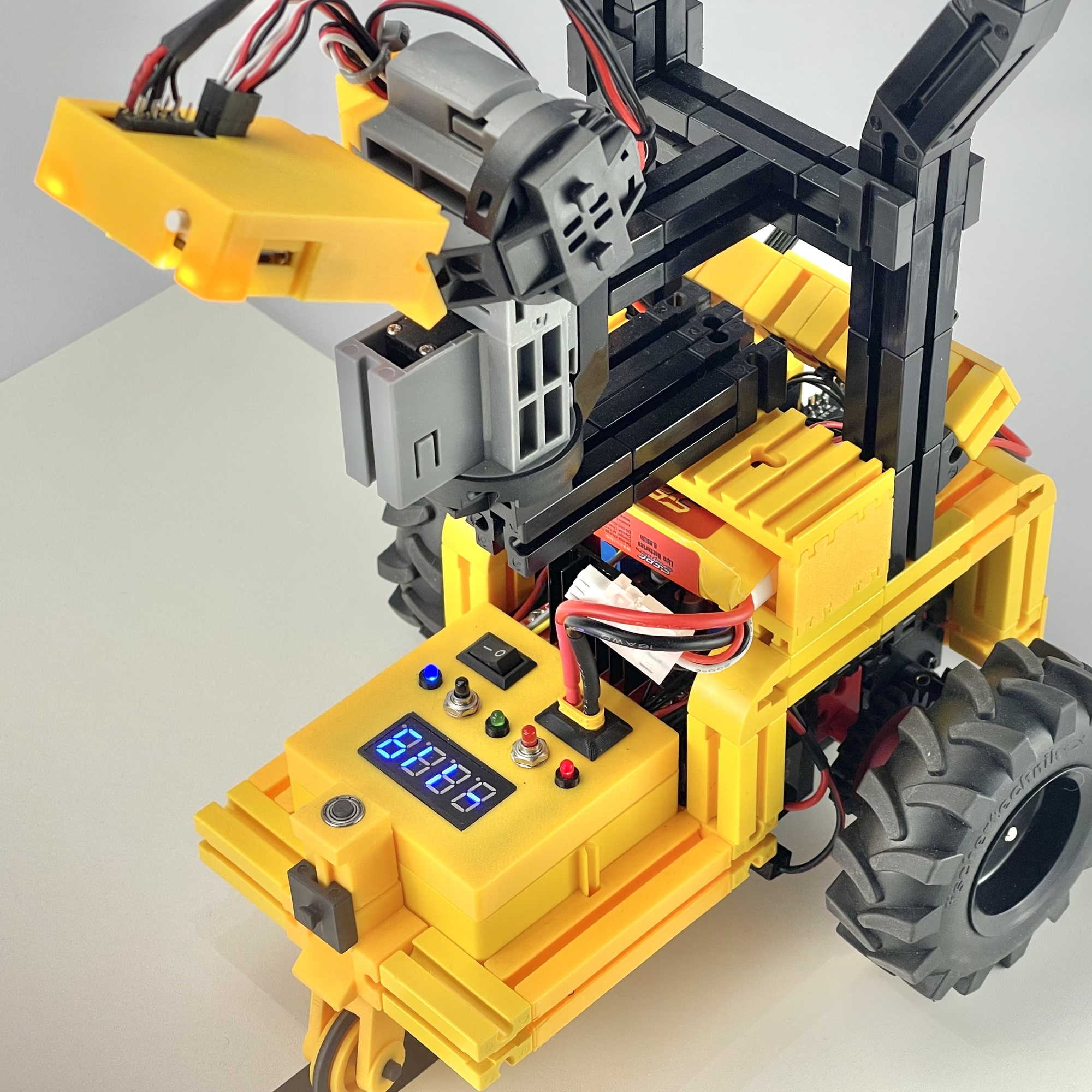
For the microcontroller, I chose a 30-pin ESP32 WROOM32 in a development/expansion board. This board has the advantage of generating its own 5-volt power supply from the DC input (5 to 16 volts). This power supply is available on the board at each GPIO pin, so that sensors, servos, etc. can be easily connected using a three-pin Dupont connector. For this project, it is convenient that the expansion board can be powered directly from a compact 7.2 volt model LiPo battery. This battery is connected directly to the yellow fischertechnik cassette (32076) with a female XT30 connector, as shown in Figure 2. In addition to a fuse and an on/off switch, this cassette contains a small display and a step-up boost converter that supplies the motor voltage (10 volts) for the L298N ‘dual H-Bridge’ motor driver for the two XM motors (fischertechnik nr. 135485).
To create some generic input and output options, I also included three LEDs and two push buttons. Numerical feedback can be displayed on the four-digit 7-segment display (TM1637). While driving, for example, it is used to display the current error of the PID control based on the direction vectors found. At the rear of the car, I included two small potentiometers that can be used to fine-tune the motor speed and Kp factor of the PID control, respectively (see photo on the right). These set values are also shown on the small numeric display.
The Pixy2 camera is connected to the I2C bus via the VSPI SPI pins of the ESP32 (MOSI=23, MISO=19, SCK=18, SS=5) and receives its 5-volt power supply directly from the expansion board. A nice bonus is that the Pixy2 uses a 3.3-volt I2C bus, so it can be connected directly to the ESP32. Incidentally, the camera's I2C bus is 5-volt tolerant, so an Arduino or other 5-volt microcontroller will also work without any problems.
I had owned a Seeed Pixy 2 CMUcam5 Smart Vision Sensor for several years, but had not yet utilized it. The line-following competition provided an excellent opportunity to investigate whether the camera's direction vector recognition is fast enough to find its way along a line course relatively quickly and autonomously. In an earlier article, in which a predecessor of this camera was used, it was already concluded that the fischertechnik USB camera lacks the necessary speed for this. The real-time image speed of this camera is limited by the maximum I2C speed of 400 kBit/s.
Online, you can find the specifications and capabilities of the Pixy2 camera I use, the successor to the original Pixy1 camera. The Pixy2 camera is smaller, faster, and has more features than its predecessor, including an algorithm for recognizing lines! This makes this Pixy particularly well suited for building a line follower.
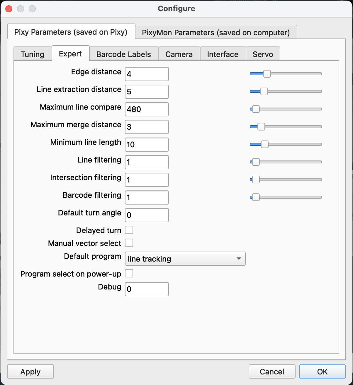
The camera can also be connected directly to the computer via a USB cable. Using the PixyMon software (available for Windows, MacOS, and Linux), the camera settings can be optimized relatively easily through trial and error (see screenshot on the right). After playing around with the settings a bit, I finally managed to minimize the number of false “recognitions.” At a speed of no less than 60 fps, the most relevant direction vector is determined for each section of the course. This data can then be easily queried via I2C and used in the control program.
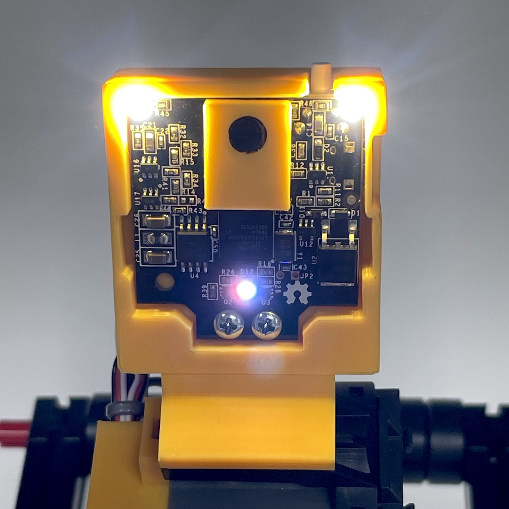
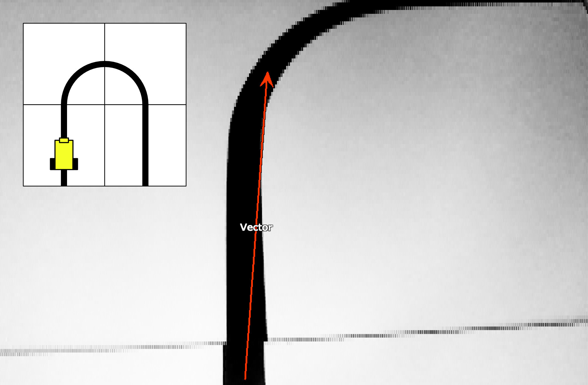
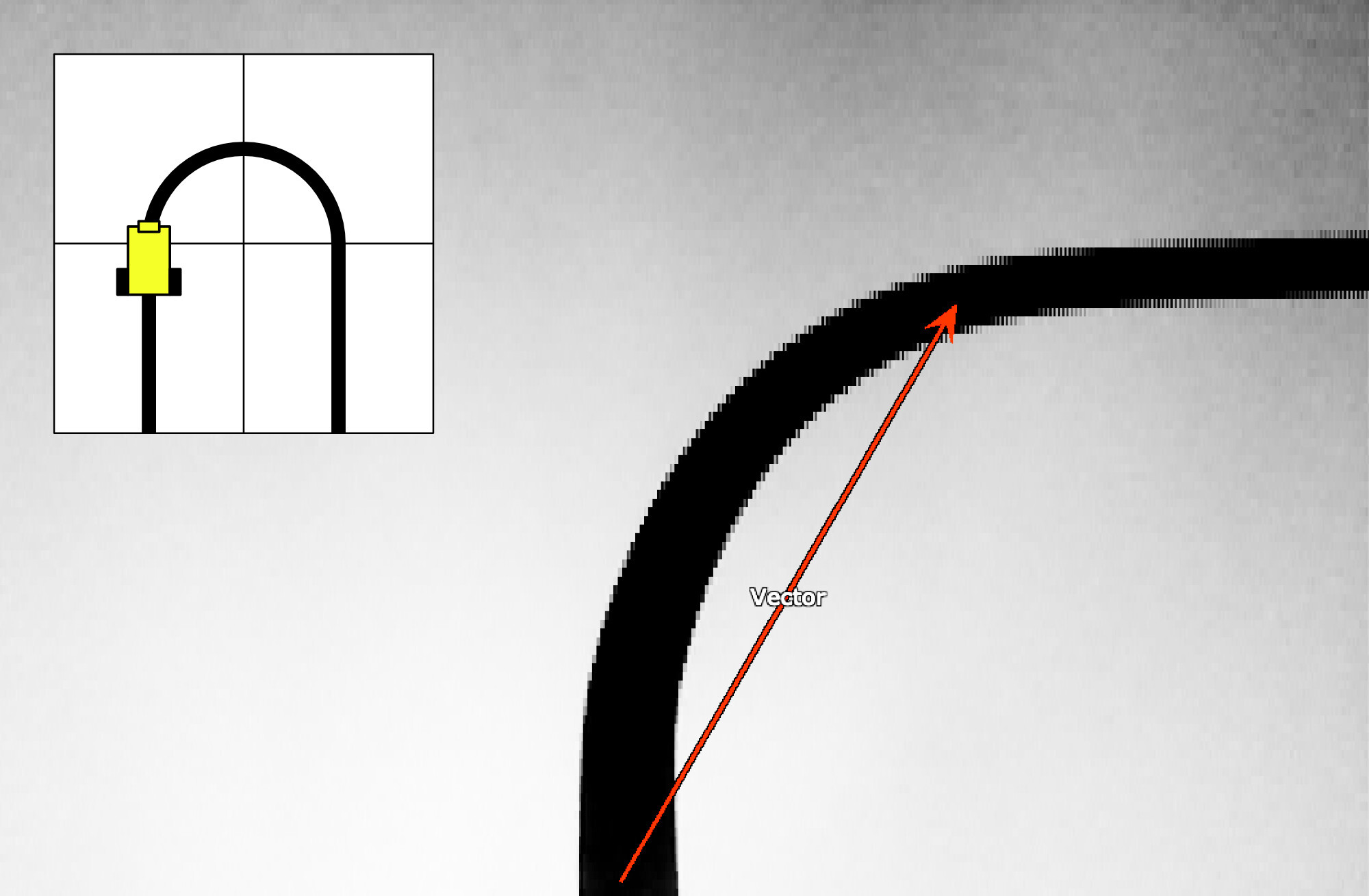
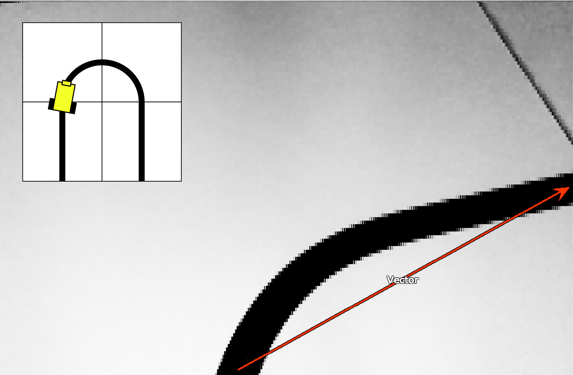
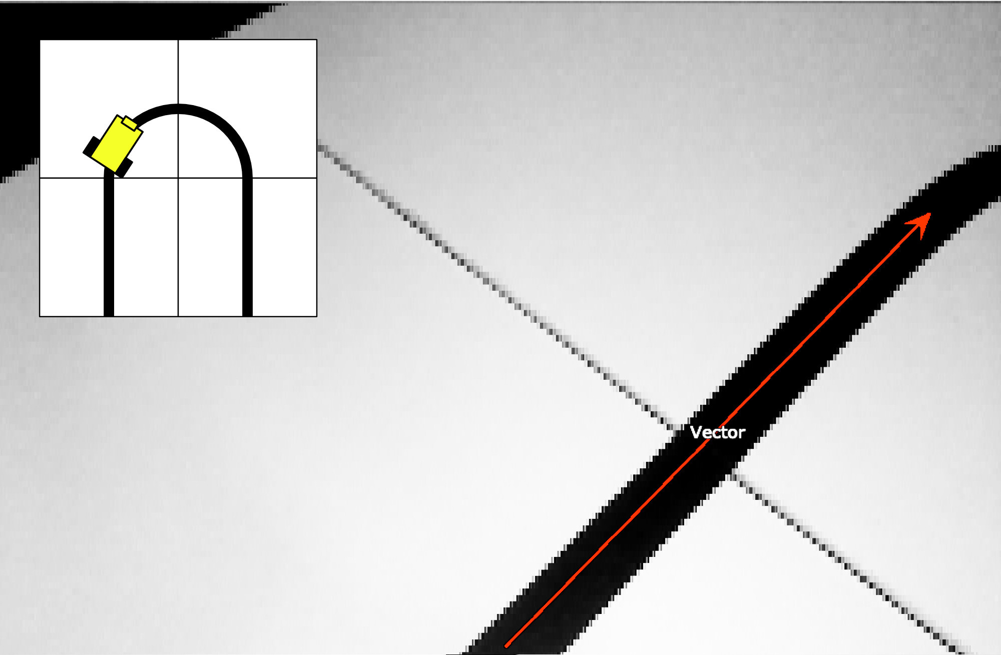
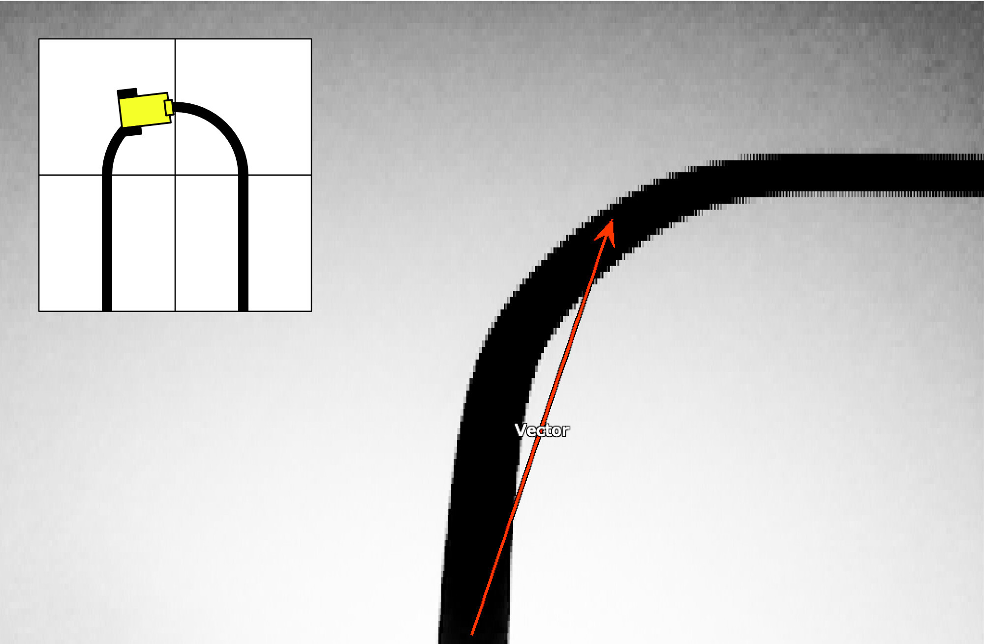
The process, to which the program will have to respond with adjustments, is illustrated in the series of images below, which show the various positions of the Robocar along a course. The camera's circuit board contains an RGB LED and two fairly bright white light LEDs (photo opposite). By switching on all the lights, the track is well lit and sufficiently recognizable. However, it was necessary to experiment with the angle at which the camera ‘views’ the track.
Looking too far ahead quickly leads to vector errors, causing the car to ‘switch’ to an adjacent track section. Looking too far ahead also means that corners are cut sharply. But looking too little ahead can also lead to problems. If the speed is not limited, the car can lose its way considerably. That is the reason for the handle on the car. This makes it possible to quickly grab the car off the track if it threatens to take the shortest route to the exit or gets stuck against a wall.
The P factor of the PID control also had to be carefully adjusted. Because I didn't want to compile and flash the entire firmware every time, I made two potentiometers on the back of the car. One allows you to adjust the maximum speed as a percentage, while the other allows you to quickly experiment with the P factor of the control to make the car drive as smoothly as possible over the line.
I based the housing on this box for the Pixy2 cam. I made the walls slightly higher and also designed the lens holder so that it could be made in the same color as the housing. Although not really necessary for the line-following function, I gave the camera a pan-tilt mechanism with two digital servos from the fischertechnik Maker Kit Bionic (571902), which could be connected directly to the Pixy2 cam print.
If the Pixy2 is connected directly to the computer with a USB cable, the PixyMon software can be used to make the camera with the pan-tilt mechanism follow a color-recognized object. For the line-following application, a camera fixed at a fixed angle might suffice, but for future expansions (such as searching for objects or avoiding obstacles in a course), the pan-tilt mechanism will certainly come in handy.
Although the Pixy2 camera can also be used stand-alone or connected to a computer, a microcontroller is required for mobile applications such as this one. I opted for an ESP32, which can be easily programmed in C++ using the Arduino IDE.
To ensure that the car drives as smoothly and quickly as possible along the track, I implemented a PID control in the software. A PID control (Proportional-Integral-Derivative) is a commonly used algorithm to continuously maintain a process value (in this case, the deviation from the line) at a desired setpoint (the center of the black line) by continuously calculating the deviation (error). The present (P), the past (I), and the future (D) influence the momentary control action. Such a control system, when configured with the correct constants, takes into account the steering characteristics (turning circle and mass inertia) of the vehicle. It is a feedback control system that makes it possible to optimize the speed of line tracking.
In short, such a control system consists of three parts:
It soon became clear that the P component has the most influence. Although I also implemented the other two components in my control loop, I minimized their influence in order to achieve a functional result as quickly as possible that would allow me to participate in the club competition. I only include the I component to a very small extent in the calculations, and I am ignoring the D component completely for the time being.
A few random samples made it clear between which values the Kp, the fixed influence factor for the P component, should approximately lie. If this value is set too low, the car can lose its line in sharp turns. If the value is set too high, the car will constantly overshoot the line and then steer too sharply in the opposite direction. There are many videos on YouTube of line followers that suffer from this problem.
The Pixy2 camera proved relatively easy to connect and configure and invites further experimentation in the future. Recognizing and avoiding obstacles on the track is just one of many possibilities. The ESP32 microcontroller used, which is equipped with WiFi and Bluetooth, also offers the possibility to monitor or control the Robocar wirelessly. I had already made a small setup by developing a simple app for the iPhone (using Python with Tkinter) that allowed the Kp constant to be configured during the ride. However, it turned out to be easier to simply adjust this one-time configuration with a potentiometer on the car itself.
The two other line followers in the first photo above use a more conventional sensor technique to follow the line. These cars use infrared sensors. When we run the different Robocars consecutively on the same track, there is an (explainable) difference between these methods: the Robocar with the Pixy2 camera anticipates and cuts corners, while the Robocars with the IR sensors can only correct. They take wide ‘outside corners’. In the future, I will discuss these cars with IR sensors in more detail.