
Elsewhere on this website, a module with two so-called H-bridges is described, which can be used to control the speed and direction of rotation of two motors. A key advantage of this module is that, when control of the motor’s direction of rotation is unnecessary, each set of two (motor) outputs can also be used as two separate driver outputs (so-called half-bridges). This allows up to four individual loads (such as lights, motors, pneumatic valves, etc.) to be controlled.
The module can directly power the connected loads using the module’s supply voltage, which is provided via the metal strips on the sides of the module. For more demanding loads, an external supply voltage can be provided.
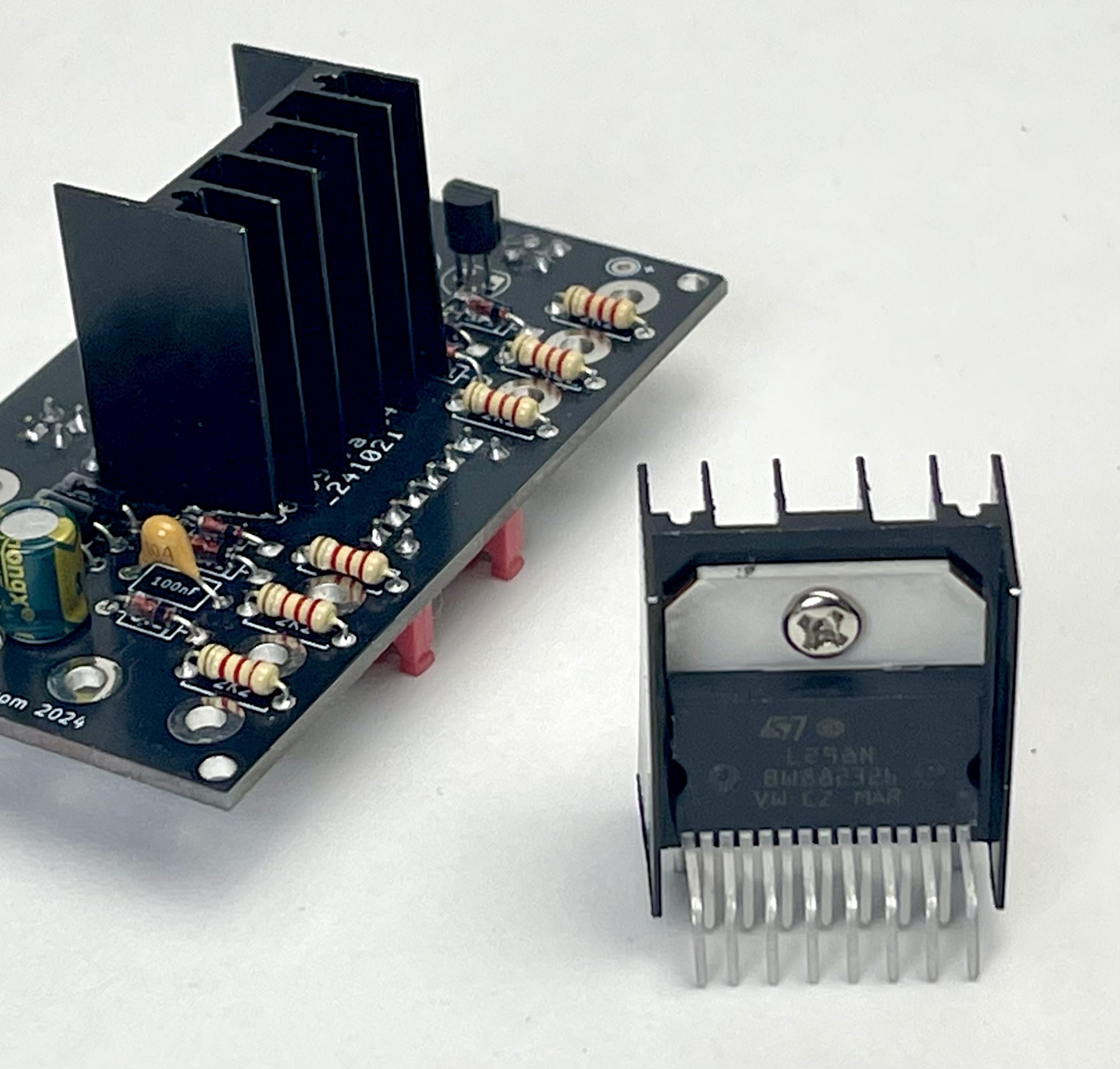
This dual H-bridge module contains an L298N chip for driving the connected loads. The module has a maximum continuous current of 2 amps per channel and can handle peak currents of up to 3 amps. The voltage of the external power supply must be between 5 V and 35 V DC.
All of the module’s connections, which are compatible with standard 2.5mm fischertechnik connectors, are also provided as Dupont pins to facilitate experiments using jumper wires and a breadboard. This module turns out highly versatile, thanks to its extensive connectivity options.
The motor/load current can be supplied externally via the DC plug (5.5 mm with 5.2 mm + pin) on the back of the module. The JST connector, PCB pin header, or standard 2.5 mm fischertechnik connectors can also be used for this purpose.
The table on the right shows the options for controlling the direction of rotation of a DC motor connected to outputs O1/O2 and/or O3/O4 using the corresponding input signals IN1/IN2 with the ‘enable’ input ENA and IN3/IN4 with the ‘enable’ input ENB.
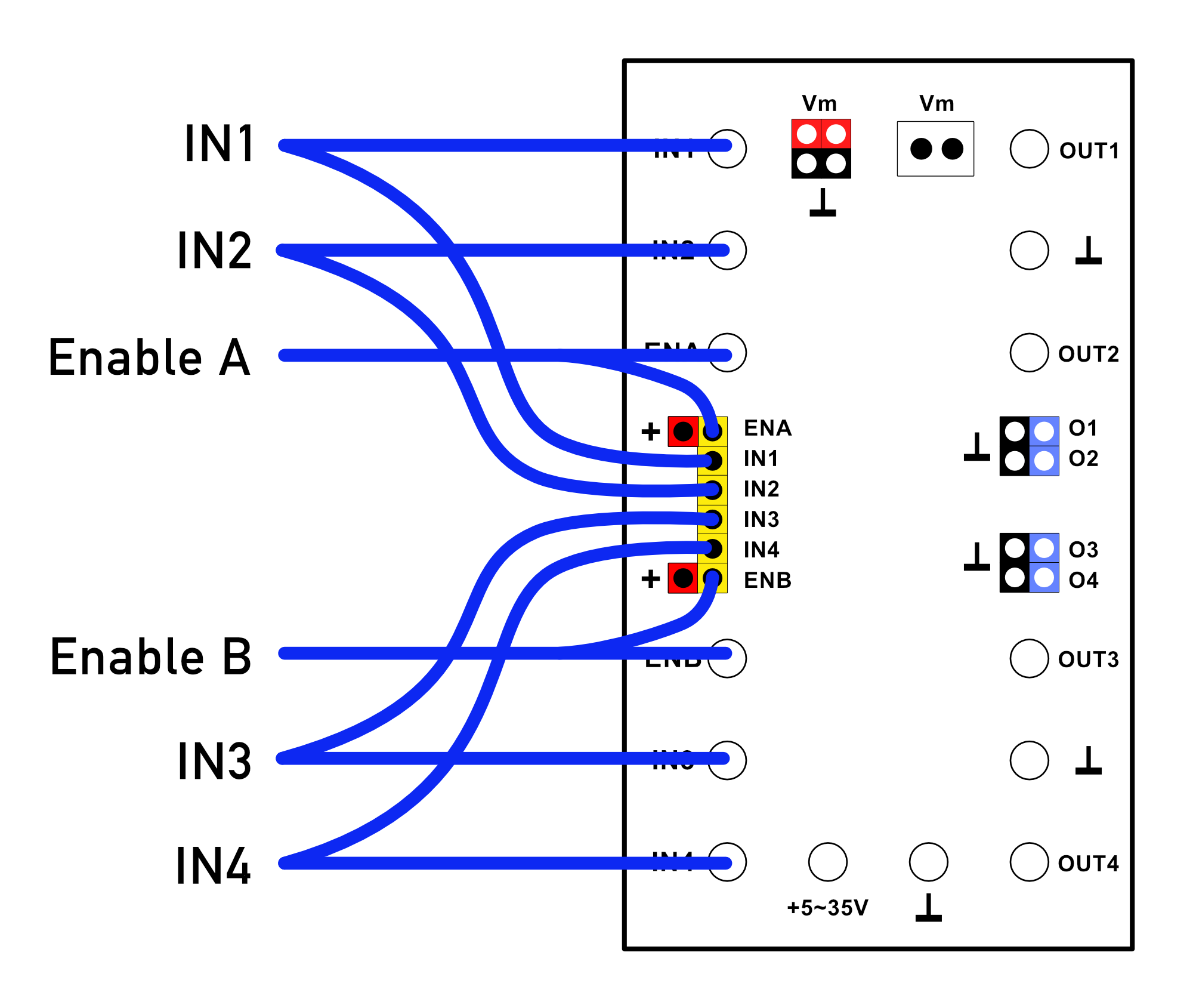
If a ‘low’ (or no) signal is applied to the ‘enable’ input, the two corresponding outputs will also be ‘inactive’, regardless of the control signals applied to the inputs. If the ‘enable’ inputs are not needed, an ‘active’ input signal can easily be applied by placing a computer jumper on the corresponding ‘enable’ input. A red pin (carrying the positive operating voltage) is provided next to these inputs for this purpose.
In most simple experiments with the module, both computer jumpers will be placed on the ‘enable’ inputs.
| IN1 | IN2 | ENA | O1 | O2 | Motor |
|---|---|---|---|---|---|
| IN2 | IN3 | ENB | O3 | O4 | |
| 0 | 0 | 0 | 0 | 0 | Stopped |
| 0 | 1 | 0 | 0 | 0 | Stopped |
| 1 | 0 | 0 | 0 | 0 | Stopped |
| 1 | 1 | 0 | 0 | 0 | Stopped |
| 0 | 0 | 1 | 0 | 0 | Stopped |
| 0 | 1 | 1 | 0 | 1 | Turns counterclockwise |
| 1 | 0 | 1 | 1 | 0 | Turns clockwise |
| 1 | 1 | 1 | 1 | 1 | Braked |
Both the direction of rotation and the speed of each motor can be controlled. The direction of rotation can be selected by setting one of the two relevant inputs to “active” according to the table. If both inputs (and/or the corresponding ‘enable’ input) are ‘inactive’, the motor does not rotate. If a direction of rotation has been selected by setting one of the inputs to ‘active’, the rotational speed can be controlled using a ‘pulse width modulated’ (PWM) signal on the ‘enable’ input.
A detailed discussion of the possibilities of pulse width modulation is beyond the scope of this manual. A wealth of information on this topic is readily available online.
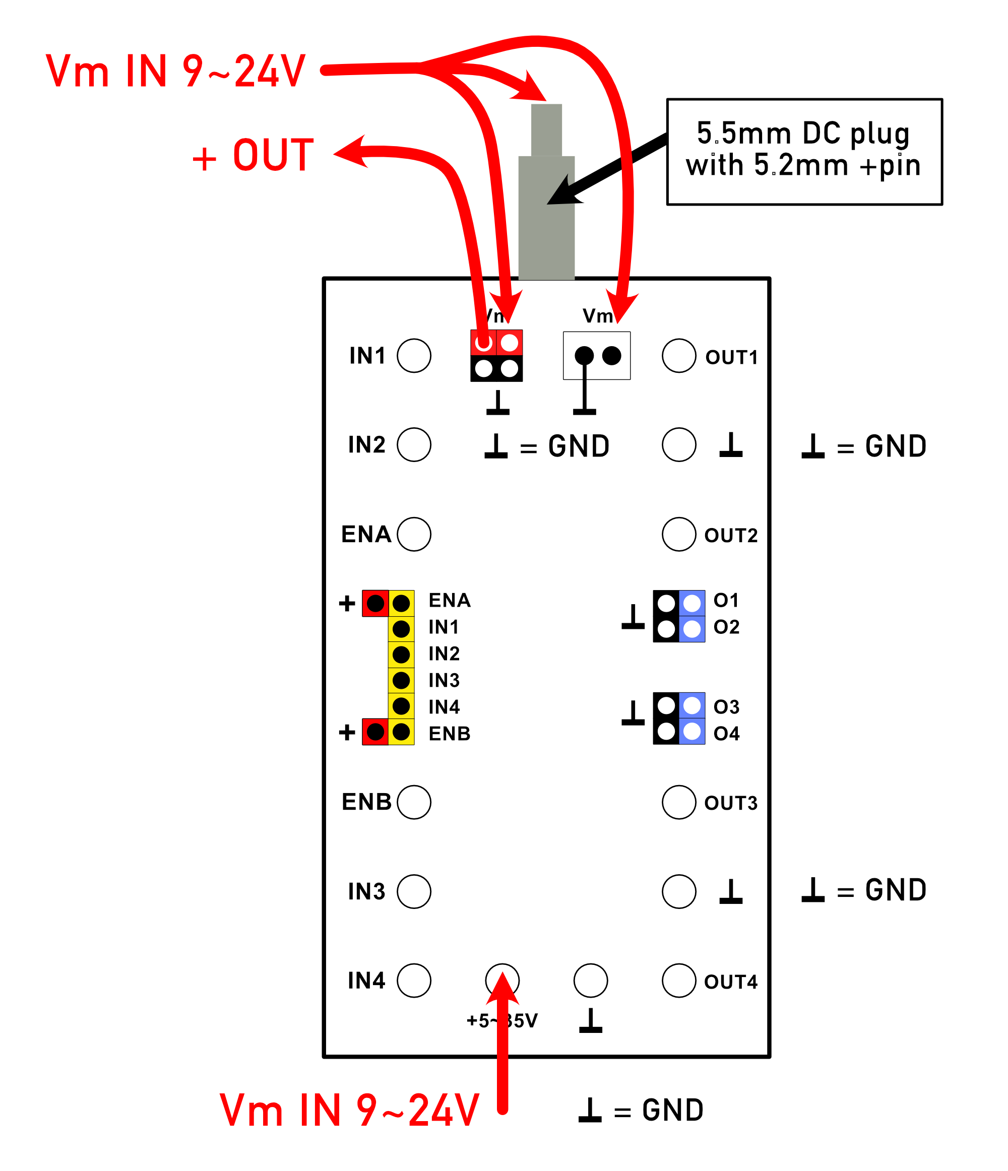
If the combined power consumption of the connected devices is relatively low, the standard power supply provided via the metal strips on the sides of the module can be used for this purpose. To do this, a jumper (computer jumper) must be placed across the two top red ‘Vm’ Dupont pins. As long as ‘Vm’ is connected in this way, the supply voltage provided via the metal strips on the sides of the module can be tapped from the supply voltage terminals at the bottom of the circuit board, as well as via the JST connector. In the classic fischertechnik ‘Silberlingen,’ this is typically around 10 volts.
The image on the left shows the options for supplying an external power supply once the ‘Vm’ computer jumper has been removed.
As long as the computer jumper is placed on the two red “Vm” pins, the externally supplied power voltage is also supplied to the module's metal strips and used as the main power supply for the module, or for any other connected Silberling modules. Once the computer jumper is placed on a maximum of one H-Bridge module, you should not use any other power supply module (such as the fischertechnik rectifier module). The module, and any other adjacent Silberlingen, are automatically powered by this external supply voltage. If other classic Silberlingen are also powered in this way, it is recommended to use a 9-volt external DC power adapter, which can be connected at the rear with a 5.5mm plug.
It is possible to daisy-chain the external power supply with adjacent H-Bridge modules using cables with JST and/or fischertechnik connectors. However, the ‘Vm’ computer jumper must be removed from these additional daisy-chained modules!
If you wish to power a series of adjacent H-Bridge modules, each with its own power adapter, there are two options:
The inputs are located on the left side of the circuit board. The inputs are dual-purpose, allowing for the use of both traditional fischertechnik connectors and experiment wires (or a combination of the two).
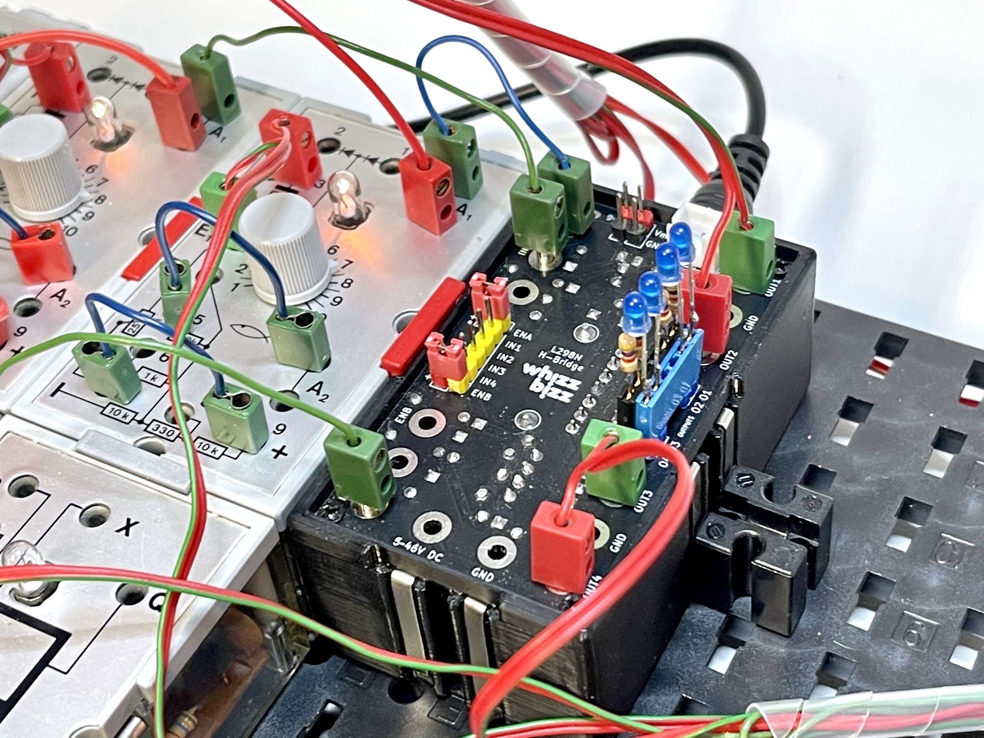
In the image shown here, no computer jumpers have been installed, so both “enable” inputs are actively used. An “active” (or PWM) signal must be applied to activate the outputs. Place the red computer jumper on the corresponding ‘enable’ input if the outputs are to directly follow the corresponding signals on the “IN” inputs.
Please also note that the ‘Vm’ jumper is not installed. An external power supply must therefore be provided, and the connected loads will not be powered by the standard operating voltage of the ‘Silberling’ module.
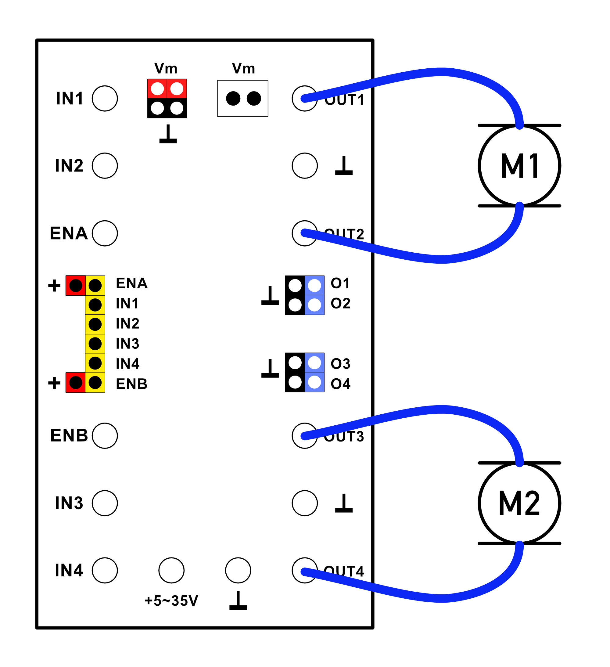
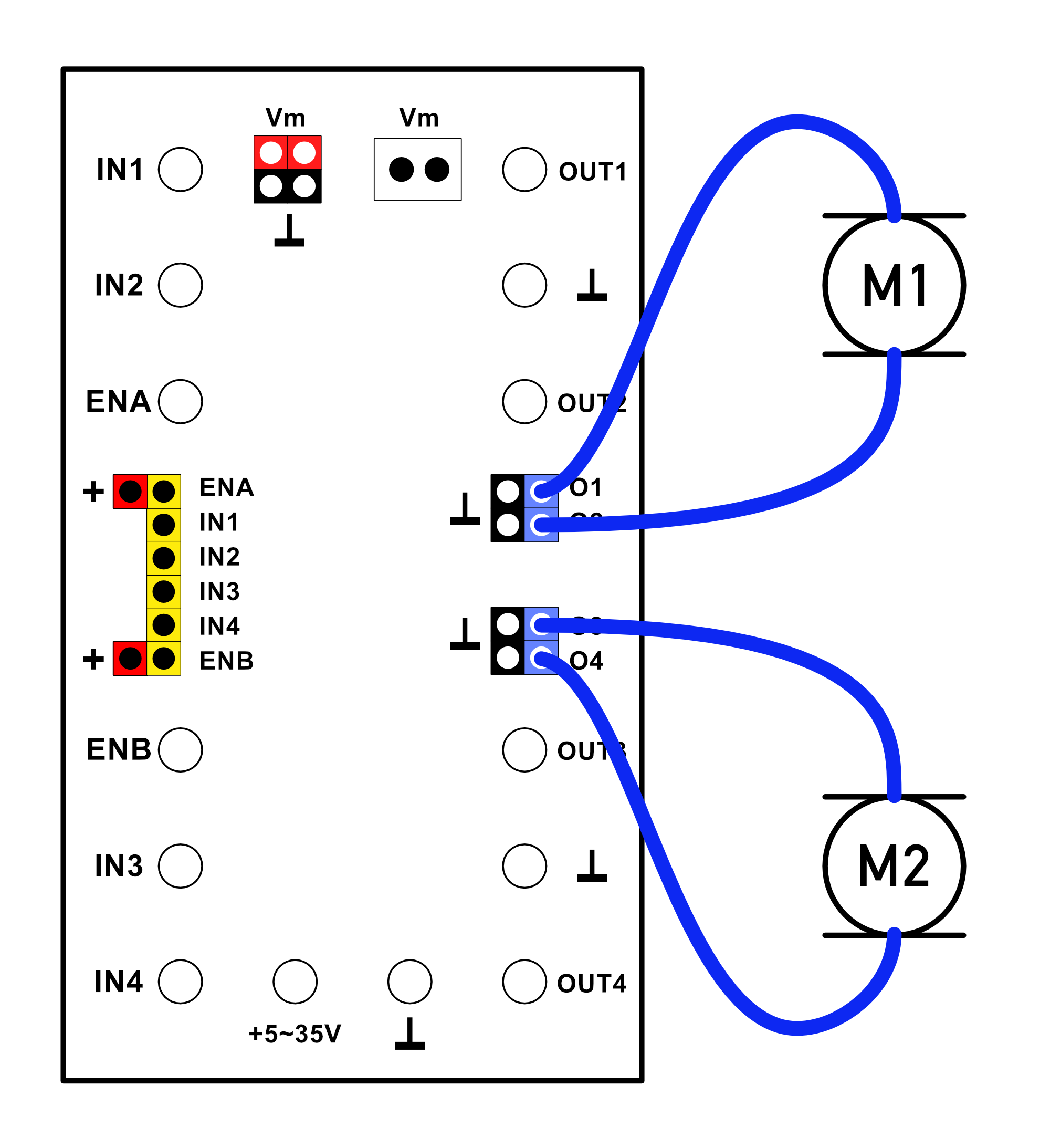
Below are two technically interchangeable options for connecting two motors to the module. In one case, the motors are connected using fischertechnik plugs; in the other, Dupont terminal rails are used to connect the motors. Of course, any combination of these connection options can also be used.
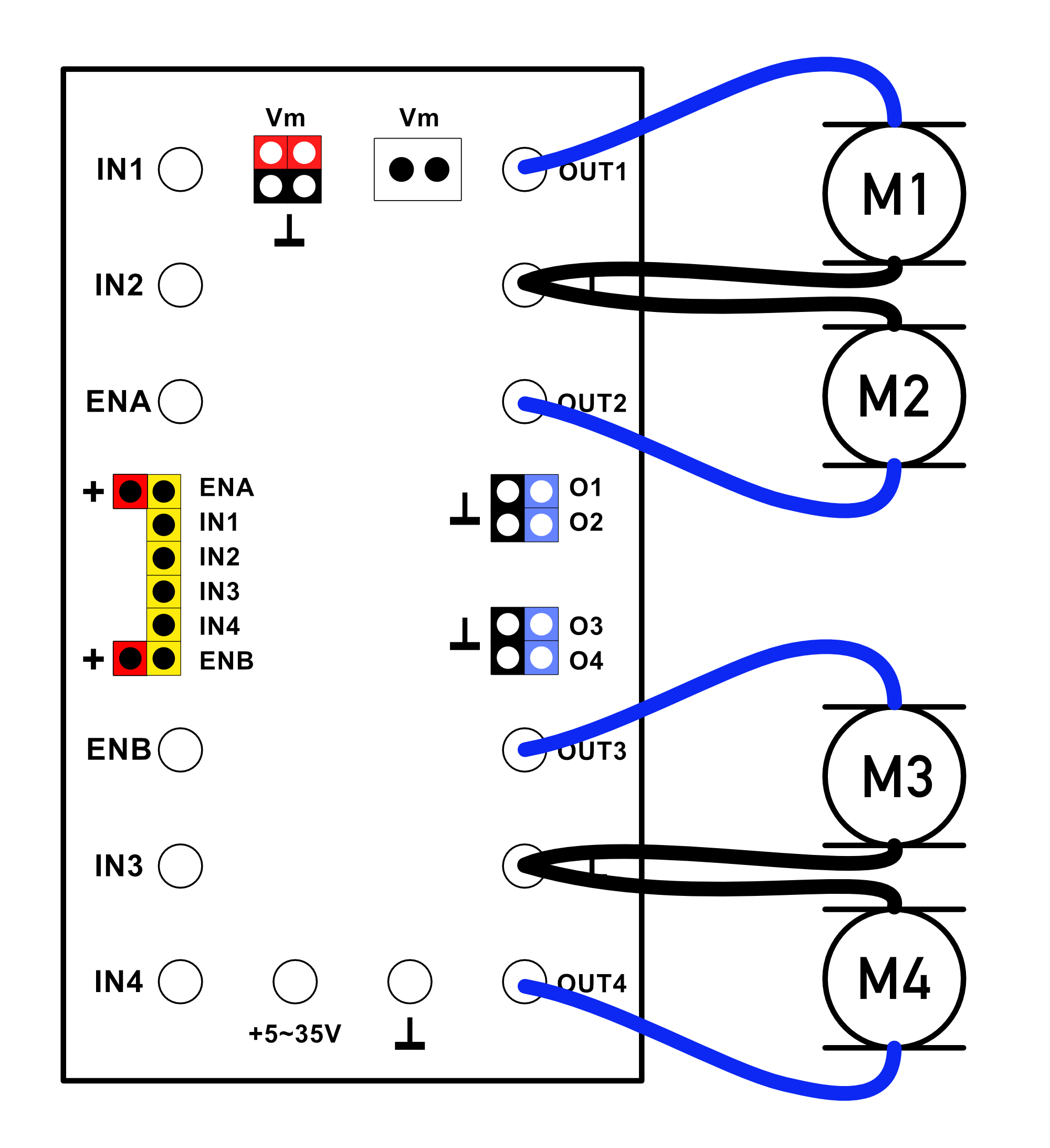
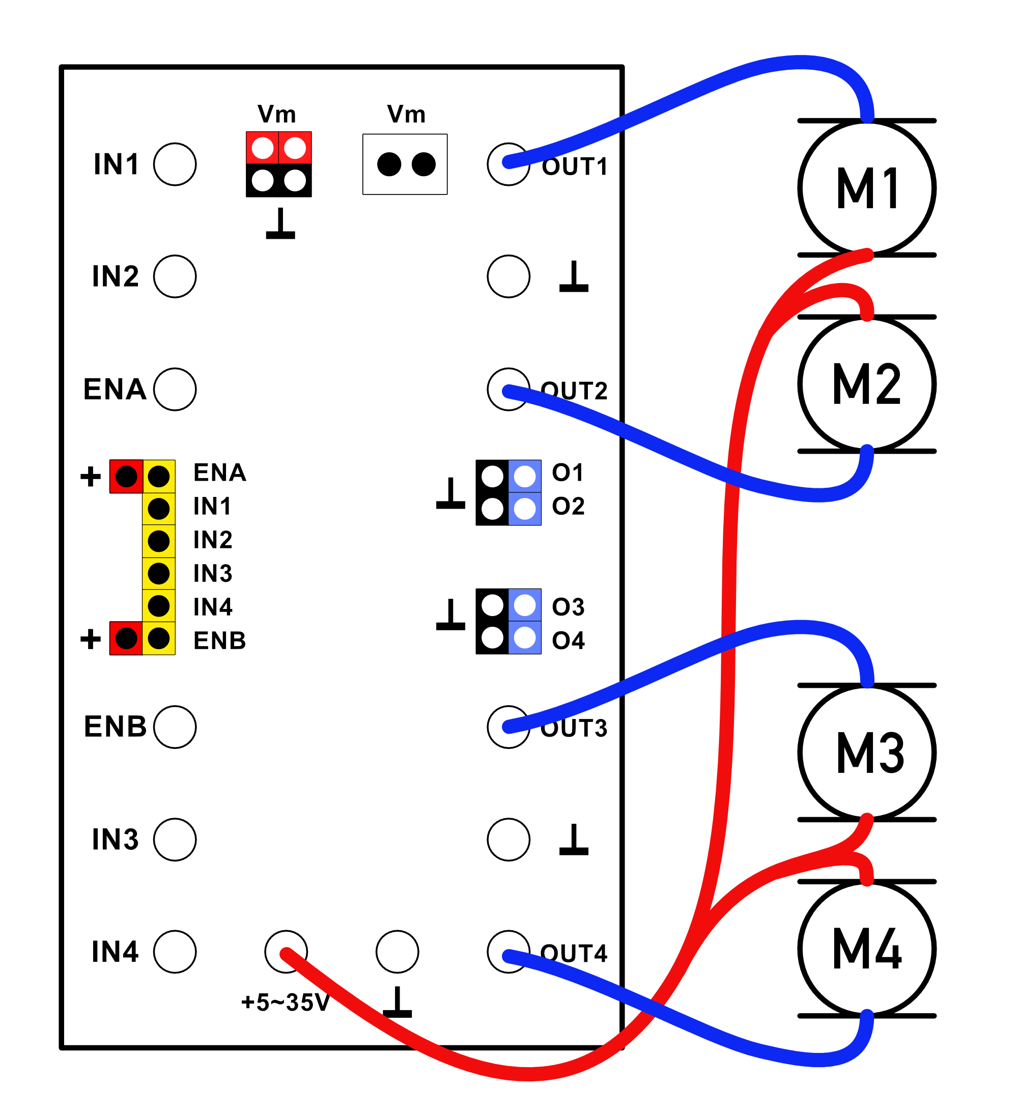
If the direction of rotation of the motors is irrelevant, all outputs can be used as separate outputs for loads, allowing up to four motors (or other loads) to be connected.
If the load is connected between the driver output and ‘ground’, it follows the so-called positive logic of the inputs. This means that the load is activated when the corresponding input becomes ‘active’. If reverse switching behavior is desired (so-called negative logic), simply connect the load between the positive terminal and the output. A motor will run normally and stop when the corresponding control input becomes ‘active’.
To further highlight the versatility of this module, here is an example application in which two light-dependent resistors (LDRs) are used to control two pneumatic solenoid valves.
The circuit works with the standard fischertechnik LDR (No. 31361, No. 32697, or No. 32698), but also with a phototransistor (No. 36134). Since the inputs of the module respond to voltage differences, a voltage divider must be created using an additional 10kΩ resistor (for example, directly in the wiring). [Click on the image to enlarge]
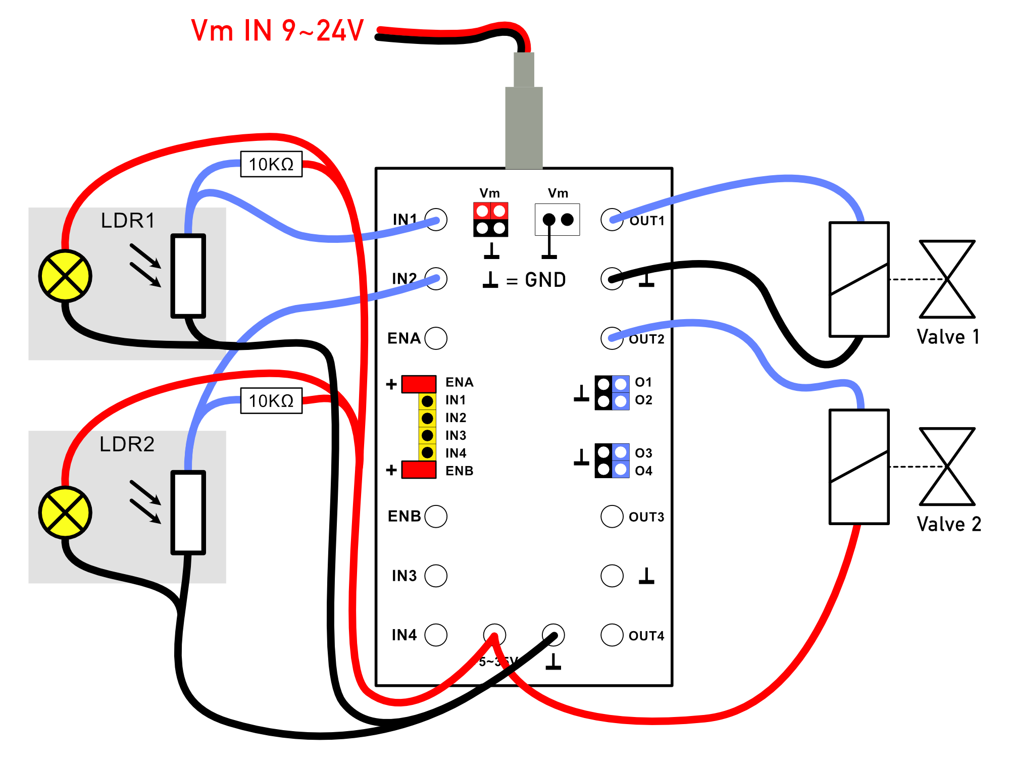
Note that (for demonstration purposes only) solenoid valve 2 is normally energized (and pneumatically opened), while solenoid valve 1 only opens when the light from the corresponding light barrier is interrupted. By connecting to either the + or - terminal as desired, the desired logical function of the input signals can be easily selected.
In the example, only two solenoid valves are connected, but the module allows for the control of up to four individual solenoid valves. Since the ‘enable’ inputs remain unused here, the computer jumpers must be installed on them.