
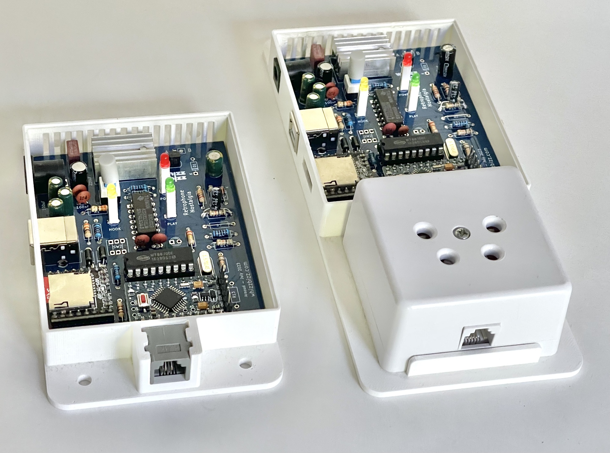
The Retrophone is built around a microcontroller (Arduino Pro Mini, 5 volts, 16 MHz). In addition to the schematic, the 3D design of the enclosure, and the PCB layout, the firmware is also open-source and can be found on the project page for the design on GitHub.
Anyone who has built the Retrophone themselves will first need to install the firmware—the program stored in the microcontroller—before the circuit can be put into use. However, anyone who wishes to modify the existing functionality and has sufficient technical knowledge can also (re)program the Retrophone. For software development, the Arduino IDE development environment is the obvious choice. It can be downloaded for free from the official Arduino website.
To (re)program the Arduino Pro Mini, the case must be opened, and a suitable programmer with a USB connection must be connected to the six pins protruding from the short side of the microcontroller board. A so-called FTDI programmer is used for this purpose, and various inexpensive versions are available for purchase online. The photos below show two versions with an FT232RL FTDI chip.
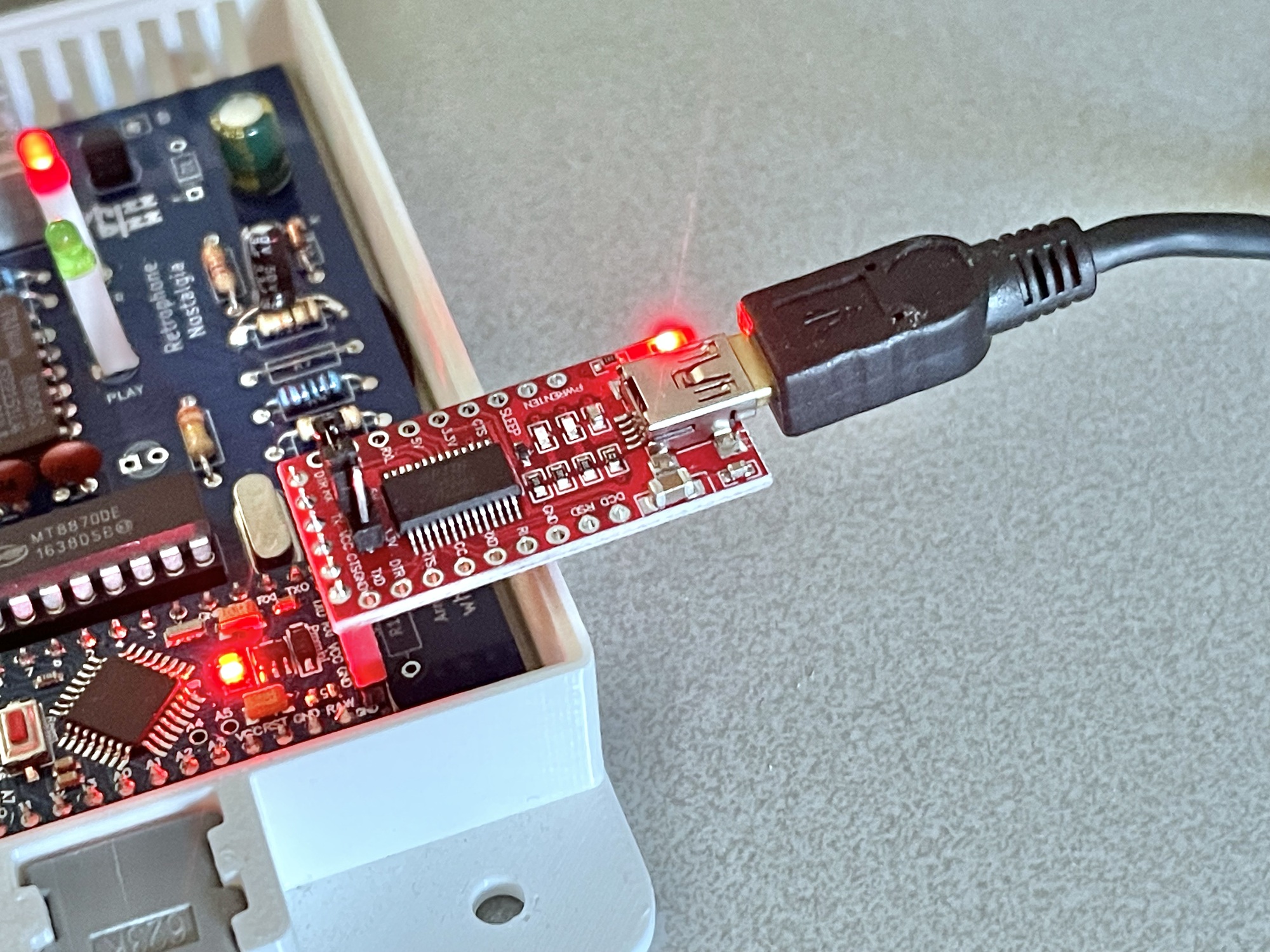
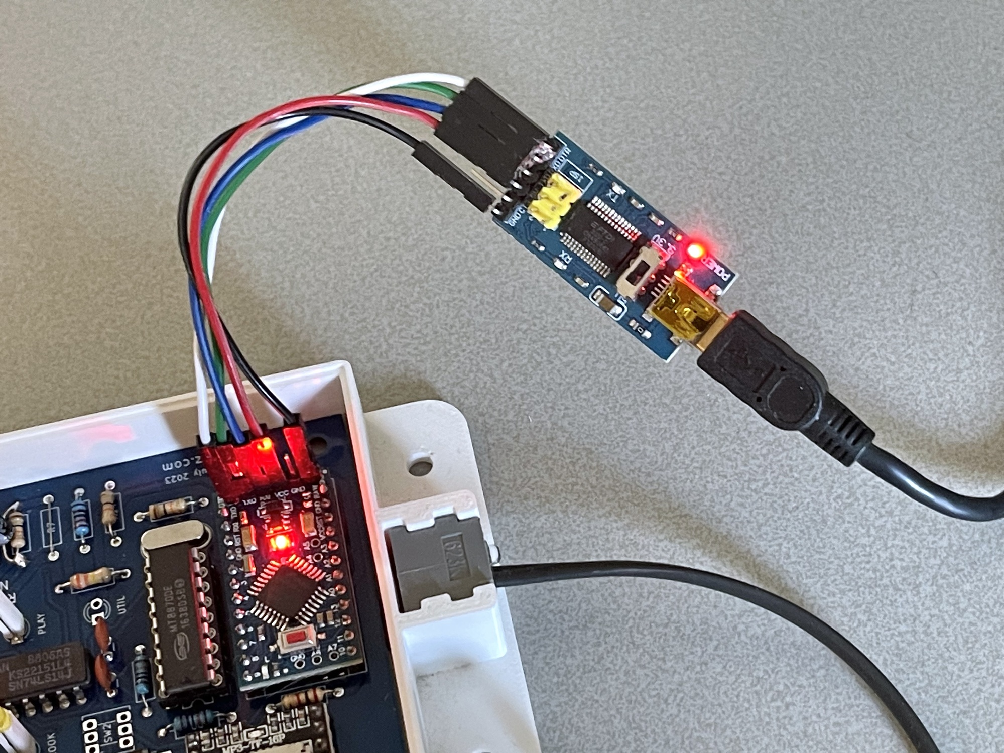
As soon as the FTDI board is connected, it will appear on your computer as a USB interface, and the software loaded or developed in the Arduino IDE can be uploaded to the Retrophone’s microcontroller.
A detailed description of programming the ATmega328P chip in the Arduino Pro Mini is, of course, beyond the scope of this document. Fortunately, there is a wealth of information available online about programming an Arduino microcontroller using the Arduino IDE.