Some time ago, I bought a kit online for a simple line-following car. The light from two LEDs illuminates two light-dependent resistors (LDRs). The motor control (via two differential amplifiers of an LM392 opamp IC) is designed in such a way that the sensors, each located on one side of the line, ‘want to avoid’ the line itself. Because only one motor runs at a time, the car moves rather nervously back and forth over the line in a zigzag motion. However, the adjustable threshold values of the two LDRs do allow a kind of ‘preferred direction’ to be programmed, but whether the cart actually takes the correct exit from the roundabout remains a matter of chance.
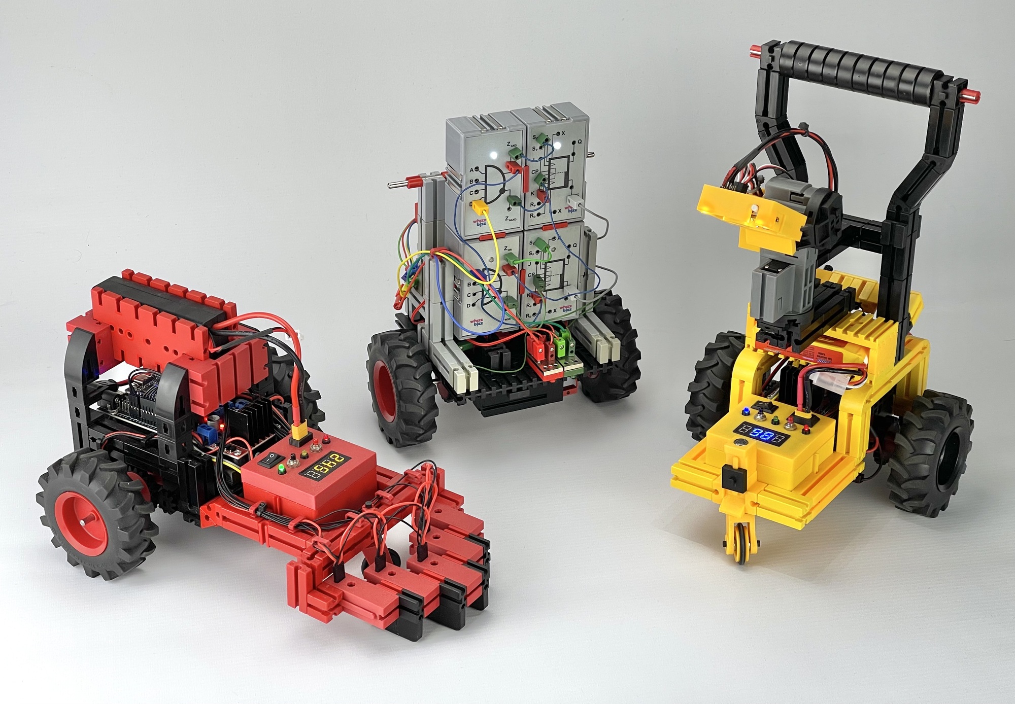
With an Arduino, ESP-32, or other microcontroller, this can of course be solved with smart software. In the previous project, I described my line-following cars that are equipped with multiple IR sensors and an AI camera. Most of the time was spent refining the software. But despite the fact that both of these ‘Robocars’ completed the club course in under 20 seconds (more than six times faster than the eventual winner), the reactions from the fischertechnik club were very lukewarm. It turned out that with 3D-printed parts and a ‘fischertechnik-unfamiliar’ controller with (barely visible) custom software for PID control, I had maneuvered myself into being the only outsider in the ‘Maker category’. To motivate myself again, and hopefully tap into more feedback and input from others, I decided to build a Robocar with simple analog electronics. This time, I added the requirement that everything had to be built with parts from the original fischertechnik program.
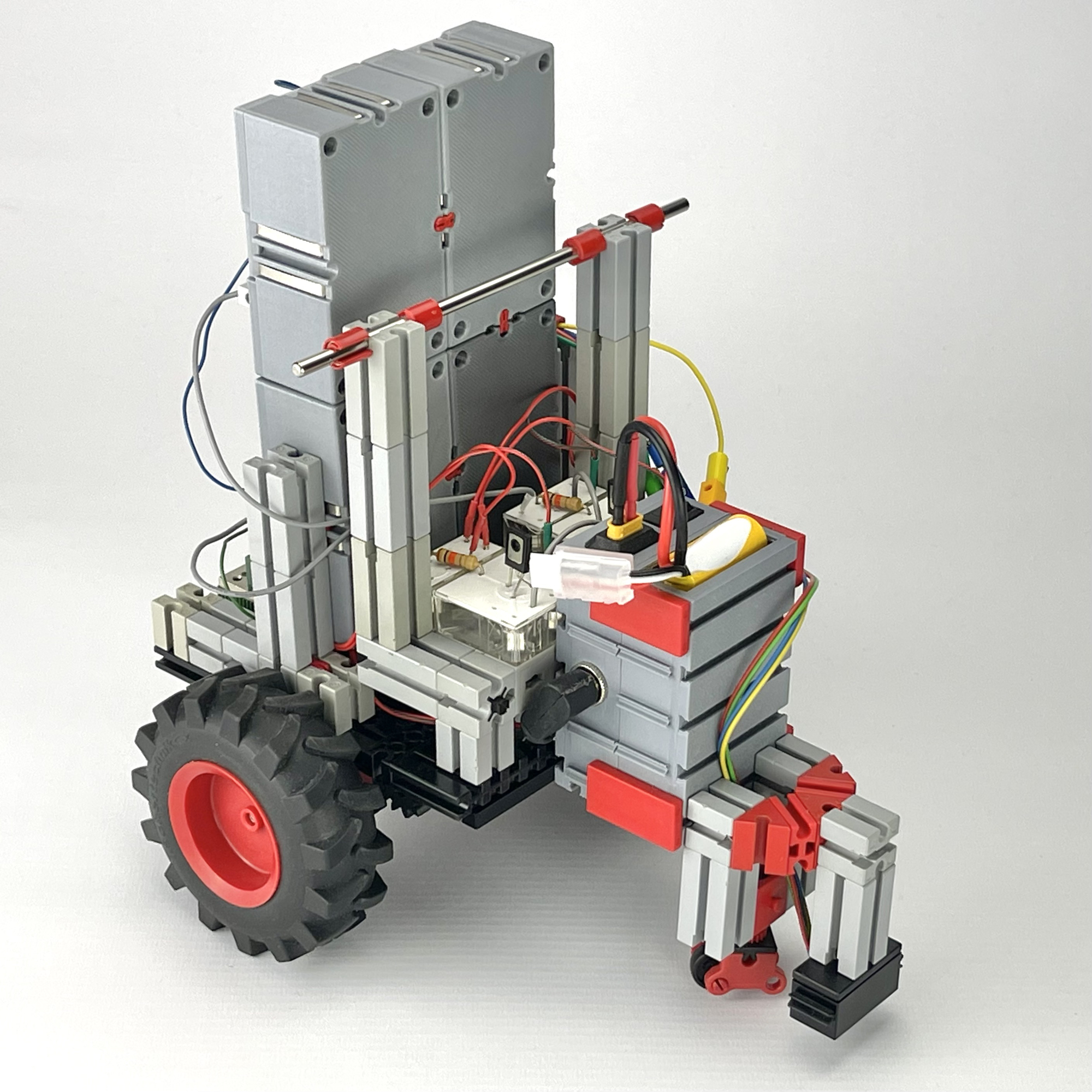
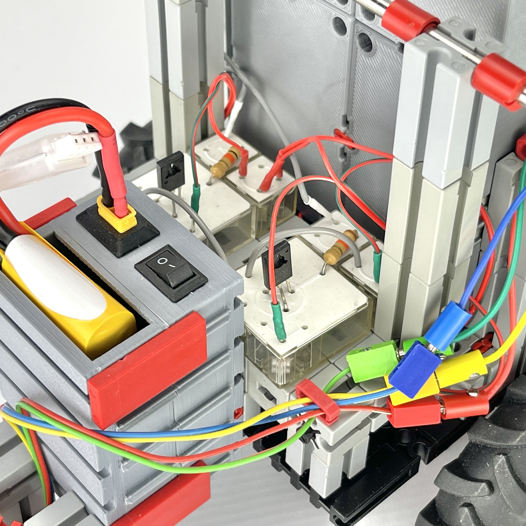
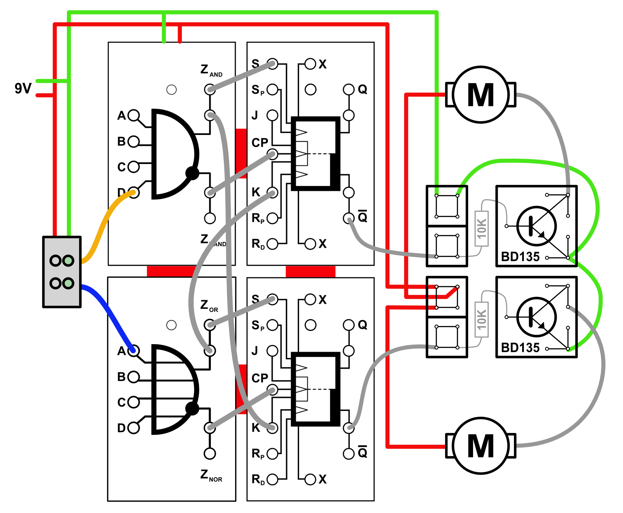
I therefore limited myself to the original fischertechnik “IR Spur Sensor” (no. 128598). This sensor is powered by 9 volts and contains two IR sensors with digital outputs. When a sensor is located above a black track, a very low voltage (almost zero) is output from this output. When the sensor moves next to the line in the white area, the output is almost equal to the supply voltage. To control the motors, I opted not for relays but for simple BD135 transistors, which were officially given the fischertechnik number 36929 in 1977 because they were part of the Elektronik-Praktikum (no. 39629). The small white plug boxes for transistors (no. 38230) and wire connections (no. 38228) from that box also came in handy for this. By using these original fischertechnik parts, my participation in the ‘real’ fischertechnik Robocar ranking cannot be denied under any circumstances. 😄
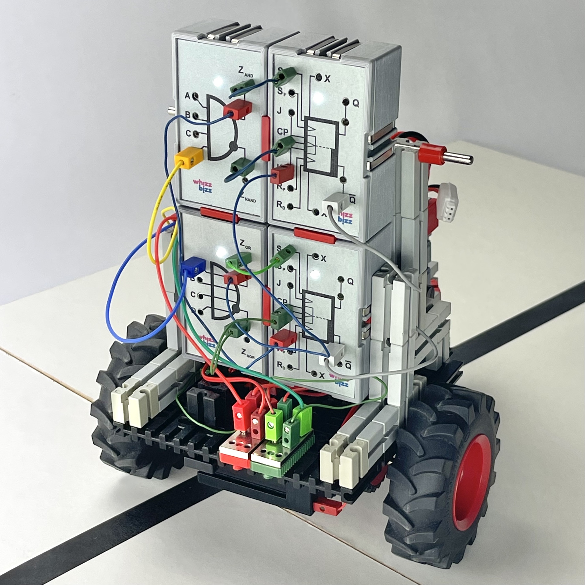
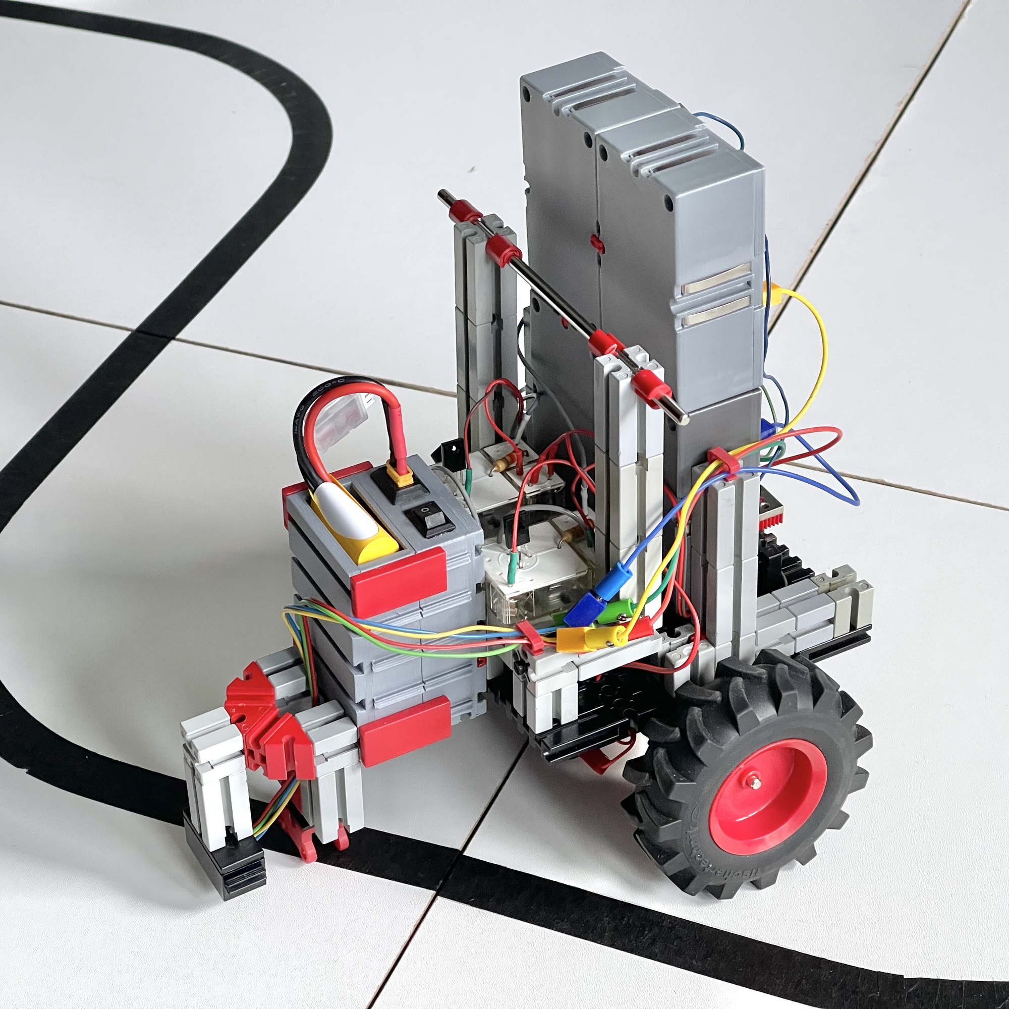
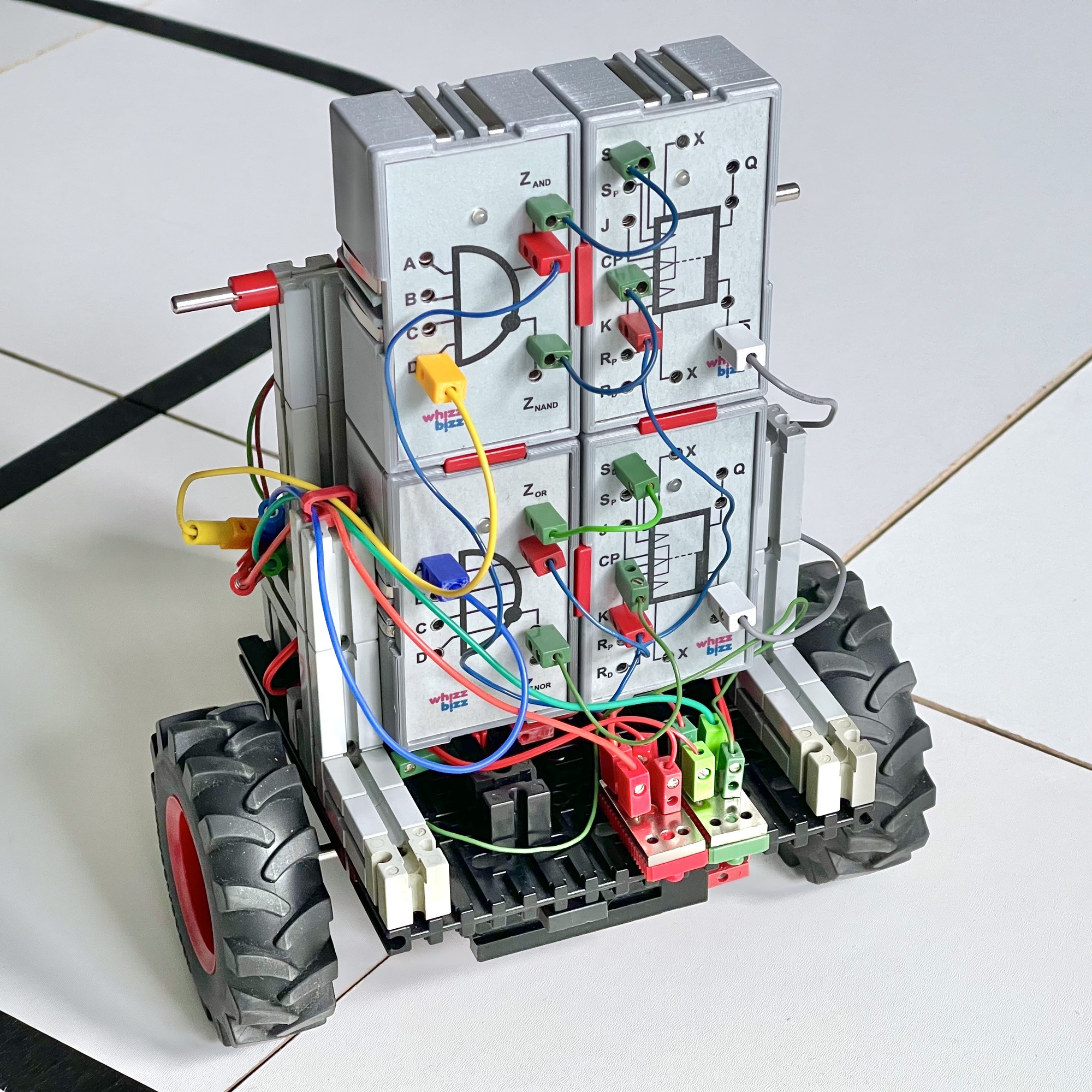
It soon became clear that it would be easier for the control system if the inverted signal level were also available from the sensor outputs. This made the choice for the traditional fischertechnik electronics modules, the so-called ‘Silberlingen’, an easy one. Because all Silberlingen offer both the normal and the complementary output signal, it does not matter which Silberlingen we connect directly behind the IR sensor outputs. Functionally, we simply need two ‘inverters’, and both the ‘Grundbaustein’ and the AND/NAND or OR/NOR building blocks can be used for this. I chose to use one AND/NAND and one OR/NOR Silberling. But another combination is also possible. The only thing that matters is that we have both the normal and the inverted signal from each sensor available. Theoretically, even the relay Silberlings could be used for this, although that would actually negate the choice of a ‘modern’ motor control with transistors. I therefore opted for a less noisy, fully ‘solid-state’ solution.
The basic idea behind the system is that at least one motor should always be running. Returning the vehicle to the line should therefore be achieved by (temporarily) stopping the motor on the other side of the vehicle. Once the vehicle is back on the line, both motors can start running again until a new steering correction is needed. In the simplest form, the motors could be controlled directly by the logical signals from both sensors. But then one sensor would have to remain on the line at all times. As soon as both sensors leave the line, both motors will stop and the car will come to a standstill. This obviously limits the speed of the car enormously.
It becomes more intelligent if we can create a kind of ‘memory’ by having each sensor control a flip-flop. The desired adjustment then remains in effect until the car has been returned to the line from the side where it left it. Because the motor current control with the transistors basically follows ‘positive logic’, we can then use the inverted outputs of the Flip-Flops for this purpose. However, before this control system can be considered truly ‘intelligent’, a few conditions must be met:
If we switch on the car as soon as it is in the middle of the line, we can assume that both sensors have a low output voltage. For the Silberlingen, with their ‘negative logic’, this is ‘active’. Condition 1 can therefore be easily met by using the inverted sensor signal on the Sd input of the relevant Flip-Flop.
If we use the non-inverted signal from the sensor (in my case, the ZNAND or ZNOR output) on the CP input of the flip-flop, it will ‘reset’ the flip-flop every time the sensor touches the line. The motor switches off and only the motor on the side where the line was left continues to run so that the car will steer back to the line.
We have already come a long way, but we still need to meet condition 2, because otherwise the car will stop completely if the other sensor also leaves the line before the car can be returned to the line.
So we are looking for a method to ‘freeze’ the Flip-Flop that controls the (only) motor still running at that moment. In other words: only the first sensor that leaves the line determines which motor switches off, until this sensor returns to the line. Until that moment, the measurements of the other sensor should simply be ignored. After all, one motor must always continue to run.
This is possible with the J and K inputs of the flip-flop, which are considered ‘1’ or ‘active’ if not connected. In the description of the fischertechnik Flip-Flop module, we read that if we only connect input K (J=‘1’), we are dealing with a situation in which, if K=‘0’, the output Q of the relevant Flip-Flop will always be ‘1’. This is exactly what we want, because the relevant motor will then continue to run!
We can therefore meet condition 2 by connecting each sensor-inverter output to the K input of the other flip-flop. This will ensure that the first sensor to touch the line will cause the information from the other sensor to be temporarily ‘ignored’ until it has returned to the line itself. This ensures that the other motor continues to run, guaranteeing that at least one motor is always running and that the ‘memory function’ of the car is realized.
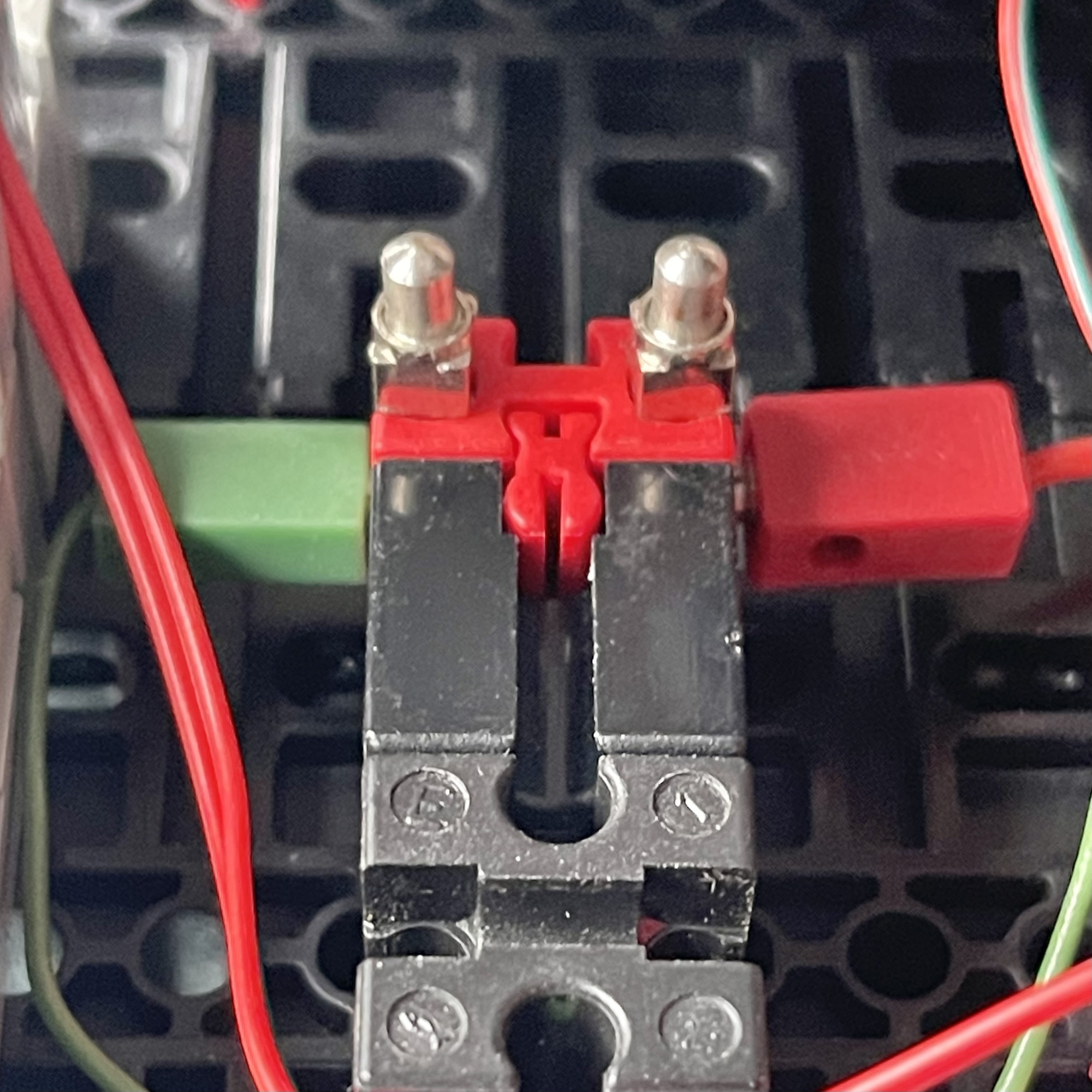
If you use (one of) the sensor signal inverters Grundbaustein (no. 30813), you can easily connect the power supply to pins 9 (+) and 3 (-) of this classic electronics module. Those who, like me, did not want to add an extra Silberling rectifier (no. 30811) for this purpose can use a 7.5 mm stone (no. 37468) with two spring contacts from an 8-position rotary switch (no. 31312) to connect the supply voltage.
Built in this way, this Robocar has little trouble with sharp turns, T-junctions, or the “roundabout” in the club course. What's more, thanks to its ‘corner memory’, it can drive a lot faster than the cars that have to limit their speed so much to prevent both sensors from leaving the line. It was the first time I was able to make good use of the K input of the Flip-Flop. After the more advanced line-following techniques described in the previous issue of the club magazine, with AI camera and process control with five IR sensors, this model is literally the final piece in the triptych of Robocar cars that I made. This Robocar does not require any additional sensors, does not use any relays or microcontrollers, and can be built entirely with parts from the fischertechnik range. Hopefully, it will be possible to demonstrate it on one of the upcoming club days on the ‘club course’.
After the two Robocars, which focused on programming the control system with a microcontroller, it was good to take a step back (in time) and try the same thing with traditional analog electronics. This underlines once again that the basic techniques for autonomous control were already available in the last century. Theoretically, it is possible to further expand this logic, which is built from classic electronics modules, and even create a simple P-control with multiple sensor pairs. However, this is by no means necessary for a fast-moving Robocar, which also has no problems with sharp turns.