
This page provides some tips for anyone who wants to build the “Retrophone” telephone jukebox for classic phones themselves. A complete list of all necessary parts, the 3D print files, and basic firmware for the Arduino Pro Mini used in the design have been open-sourced and compiled at https://github.com/Arnoud-Whizzbizz/retrophone
Everyone is warmly encouraged to use the design for their own experiments. The electronic design and software are released under the GPL-2.0 license. It is not permitted to use the designs or the firmware for commercial purposes without permission.
More information about programming the Arduino Pro Mini in the Retrophone yourself can be found on the separate page about FTDI programming. The instructions on this page can also be downloaded as an easy-to-print PDF document: Retrophone Assembly Instructions.
Unfortunately, I do not supply individual parts, kits, etc. However, (for a small contribution toward development costs) a few remaining units of the first version of the circuit boards (marked “July 2023”) are available upon request for those who want to build a Retrophone themselves quickly, without first having to have the circuit boards manufactured in a larger batch. Please contact us using the form at the bottom of this page for more information. First come, first served.
Fully built and tested Retrophones (including a telephone, if desired) are available as custom-made units upon request. For professional custom projects, a modular system is used that can be triggered by external sensors, control door openers and relays, ring the bell in the telephone, etc. Are you looking for a turnkey solution for, say, your escape room, exhibition, or art project? Contact me and I’d be happy to brainstorm with you, no strings attached!
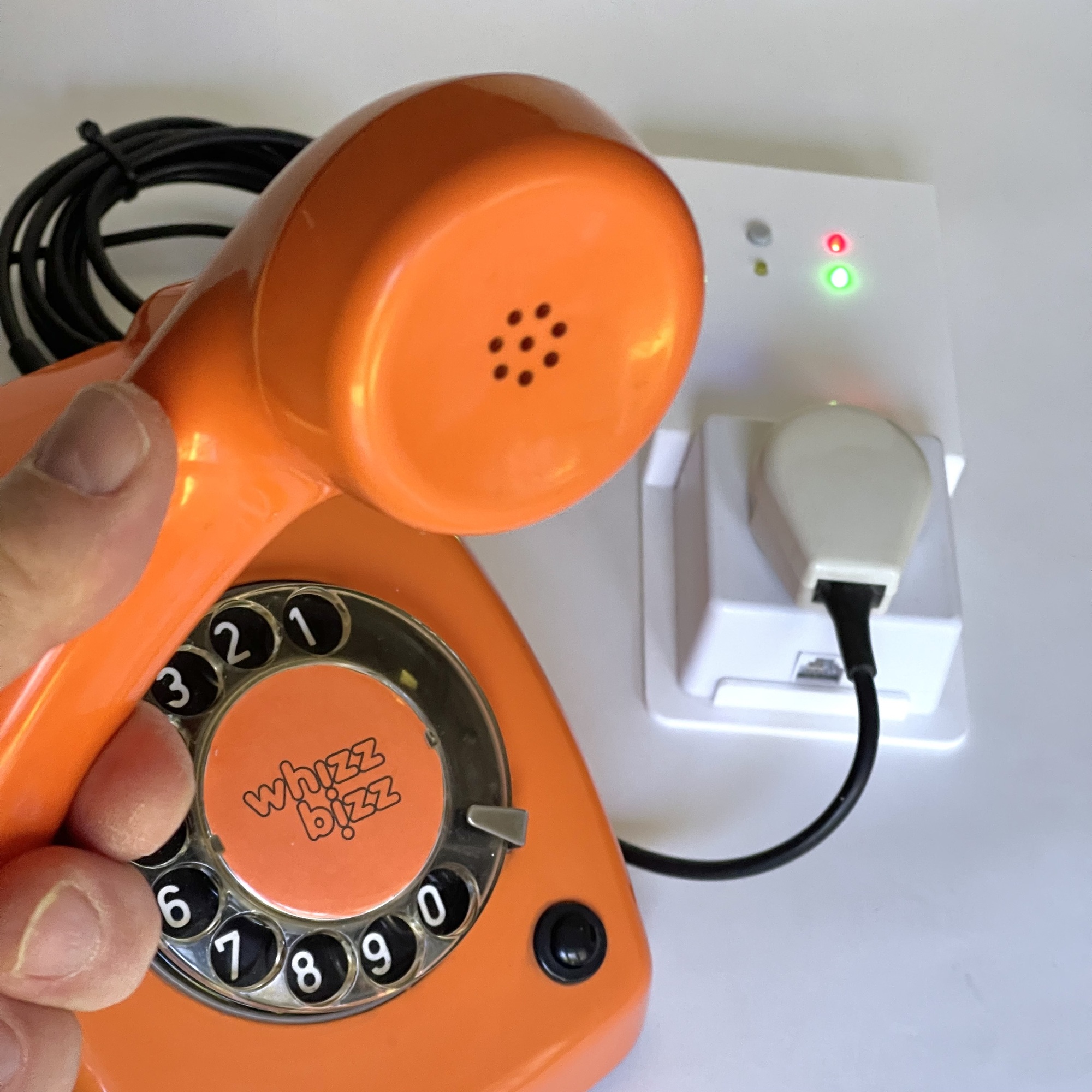
There are two versions of the Retrophone available. If you want to be able to connect a classic Dutch telephone (such as the T65) directly without any modifications, choose the model with the integrated PTT socket. The housing can be 3D-printed using the files wall-case.stl and lid-flat-basic-holes.stl.
The Q-Link surface-mount telephone jack (Part No. 00.133.44), available in the Netherlands, also features an RJ11 port for modern or foreign phones. If you only need an RJ11 connector on the Retrophone, you can choose to print the housing (or have it printed) using the 3D print files RJ11-port-case.stl and lid-flat-basic-holes-RJ11-lip.stl.
The Retrophone can be used with both traditional rotary-dial phones (such as the classic T65) and more modern push-button phones (such as the T65-TDK).
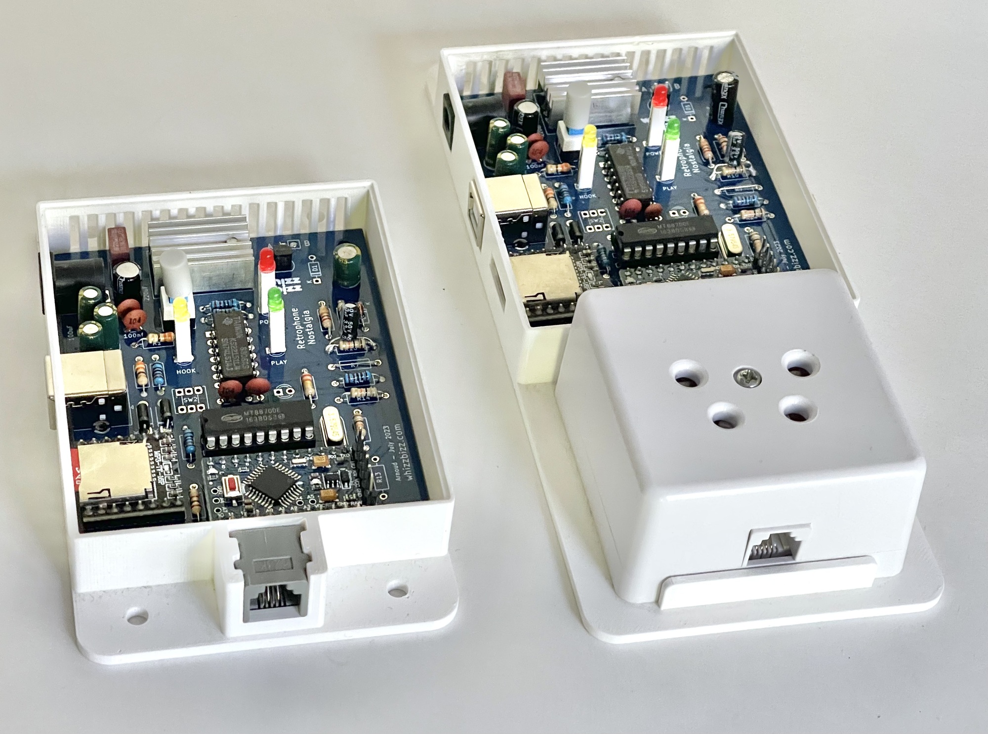
Traditionally, the dialing process for a phone with a classic rotary dial is referred to as “Impulse-Dialing” (IDK). Push-button phones are devices with so-called “Tone-Dialing” (TDK). These devices use tones instead of pulses. To use these devices, the Retrophone must be equipped with a so-called Dual-Tone Multi-Frequency (DTMF) decoder.
However, this is not necessary. If the Retrophone is used exclusively with a rotary dial telephone, the components U4 (the MT8870 DTMF decoder), the crystal Y1, the capacitors C1 and C6, and the resistors R6, R9, and R11 can be omitted.
The SW2 and LED D6 (with series resistor R13) are also optional. They do not need to be included in the standard version of the Retrophone.
This additional “configuration pushbutton” is a potential future expansion and is not currently supported in the standard firmware. For specific customization, this pushbutton can, for example, be used to add additional functionality to the basic functions.
The so-called Gerber files on GitHub have now been updated and include the “March 2025” designation, but if you are using PCB version 1 with the “July 2023” designation, there are a few things you need to be aware of