Many popular sensors and various peripheral devices are connected to the microcontroller via the I2C bus these days. However, there are several different connector systems in use, and they are certainly not all interchangeable or compatible with one another. Since I wanted to be able to connect sensors to the fischertechnik TXT4.0 Controller (with a 6-pin flat cable connection) just as easily as to the various ESP-32 and Arduino boards I use, I designed a universal I2C hub that increases compatibility between the connection systems and can directly supply power to the connected sensor.
Incidentally, this project also provided a good opportunity to map out the various I2C connector systems and to expand my ability to assemble PCBs with SMD components myself. You can read more about that further down on this page.
The fischertechnik ROBO TX Controller, released in 2009, was already equipped with an I2C interface. Since then, fischertechnik has introduced various sensors that communicate via the controller’s I2C interface (EXT). This I2C interface, like that of current Arduino boards, had a 5-volt signal level. The later-released ROBOTICS TXT Controller and the most recent TXT4.0 Controller from fischertechnik followed the modern trend of having the I2C bus operate at 3.3 volts. However, these two state-of-the-art controllers from fischertechnik were already physically incompatible because they offered a 10-pin and a 6-pin flat cable (DC3) as connection options, respectively. Since the signal levels are compatible, a simple adapter was sufficient for this purpose. Handy hobbyists (including myself—see my online catalog if you’re looking for one) have already made these themselves in various versions. The simple PCB solution can be plugged directly into the 10-pin fischertechnik sensor, while the small module version allows for the transition from 6-pin I2C to 10-pin I2C using flat cables.
Various connector systems are used to connect to the I2C bus. These are primarily determined by the various manufacturers of small sensor modules and expansion boards. A brief overview:
For (sensor) boards that do not need to communicate via the I2C bus (such as push buttons, LDRs, or controllers), many of the aforementioned connector systems are also available in a 3-pin variant, which we will not discuss further here. Care must also be taken with the 4-pin connectors because, for example, in the Grove connector system, the same four pins are sometimes used to transmit analog or digital (e.g., PWM) signals. You must therefore always verify before connecting that an I2C bus with the characteristic SDA and SCL wires is actually being connected.
In addition, the connected module must, of course, be compatible with the supply voltage provided by the connector. Fortunately, many modules today can operate at both 3.3 and 5 volts. The I2C hub discussed here provides both supply voltages via separate Grove connectors, so there will be no issues whatsoever when connecting to the sensor in practice.
In the table below, I have attempted to provide an overview of the most commonly used I2C connection systems and methods. A great deal of information on this topic can also be found online.
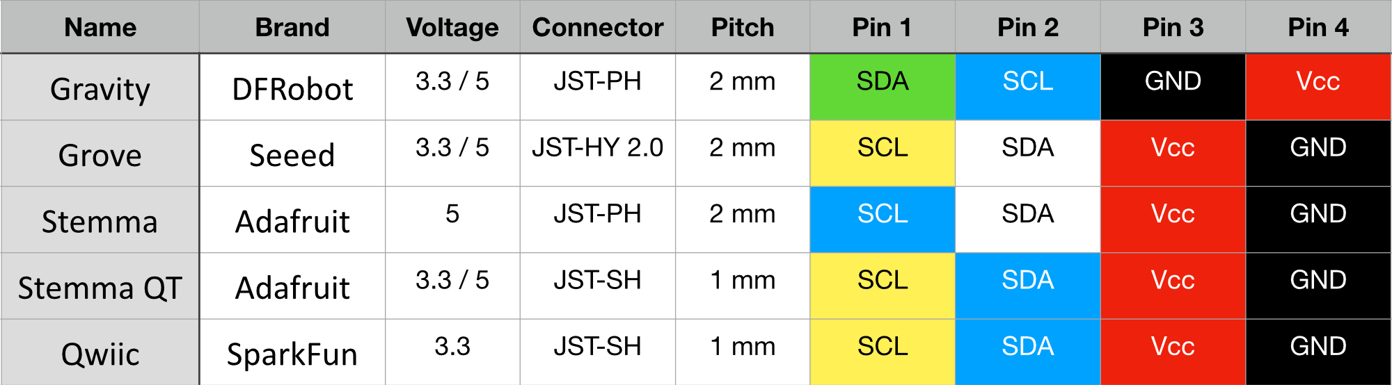
Note that the connectors used in DFRobot’s Gravity system and Adafruit’s Stemma are physically compatible (JST-PH), but the pin order differs; therefore, the pin order in existing connection or adapter cables must be carefully checked and adjusted as necessary.
In general, it should be noted that the JST-PH Stemma connector system is fully pin-compatible with the JST-HY 2.0 connectors of the Grove system. However, despite the matching dimensions and 2 mm pitch of the pins, these connectors are not physically interchangeable. Additionally, JST-HY connectors often feature a locking tab for which the corresponding recess is missing on the JST-PH connectors.
The interchangeable Stemma QT and Qwiic connector systems use smaller connectors with a 1 mm pitch that are fully compatible with each other but may differ in color. The Stemma QT and Qwiic cables therefore appear to be the only ones that can be used interchangeably without any issues. The modules to be connected typically require a supply voltage of 3.3 volts.
In summary, we can state that the connector systems used to connect the I2C bus always have four pins. Red and black are used for the positive and negative terminals, respectively, in all cases. The colors vary for the data and clock signals of the I2C bus. The CLK is usually a yellow wire, but sometimes blue. Green, white, and blue are used for color-coding the I2C data.
It seemed sensible to me to use a single central connector system when connecting various I2C sensors and peripherals, and to use custom adapter cables when necessary. Given the wire colors and the distinctly different form factors of the connectors across the various systems, this seemed to me to be a less error-prone and more universal solution than building an arsenal of custom flat cables with individually cut and stripped wires, each intended for only one specific application. This keeps the setup organized, reduces potential connection errors, and makes it easier to mix and match different components within a project.
Since I find the flexible, colored cables easier to work with than the gray flat cables, which can sometimes be difficult to bend, I decided to make Grove/Seeed connectors a central part of my setup. Adapters and extension cables from all common connector systems (see the table above) to Grove are readily available.
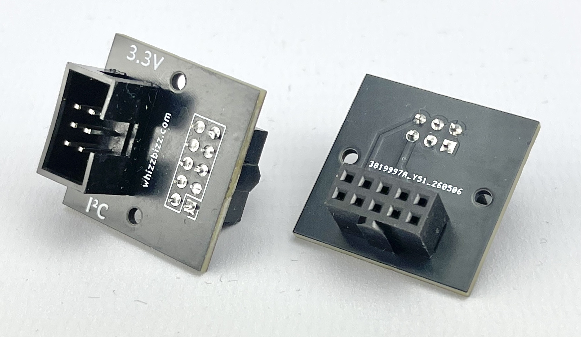
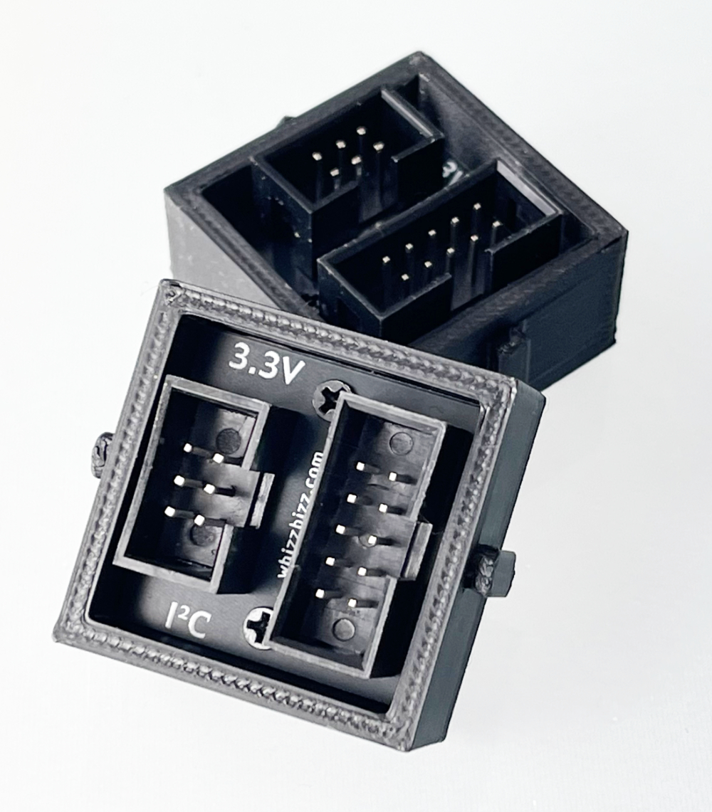
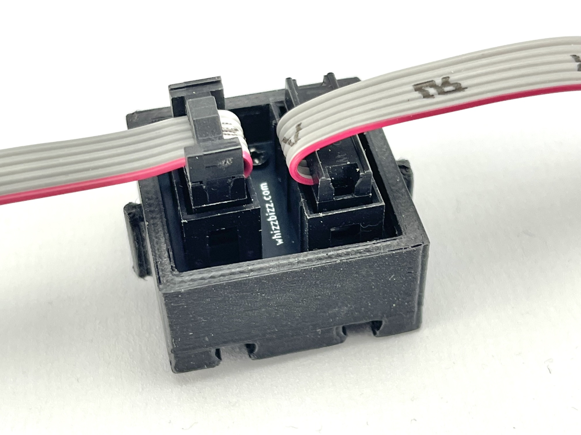
Of course, it’s even more flexible to be able to make these yourself to any desired length. The individual JST connectors can be assembled using a good JST crimping tool, and where a 2x3 (or 2x5) pin header is desired, it can be soldered. I personally protected the solder joints with a piece of colored heat-shrink tubing. Since I could only find the mating part for this type of connector in the DC3 variant—which is designed to be crimped onto flat cable—I designed and 3D-printed a sleeve to mimic the specific IDC connector with the tab using a standard “female” Dupont pin header (image shown here).
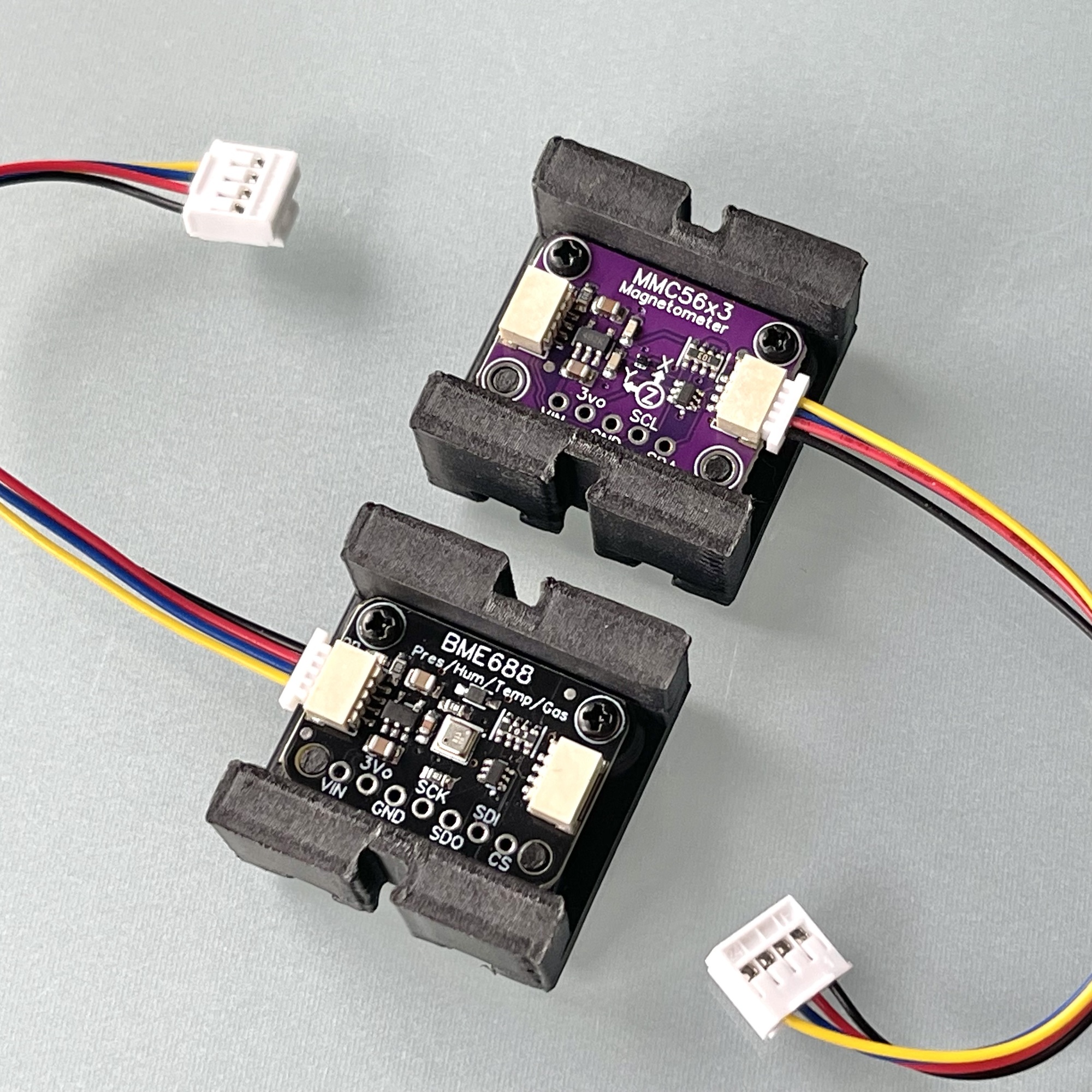
Adapter cables from Qwiic to Grove connectors are available for sensors equipped with the small Qwiic connectors. The image on the right shows a board with the MMC5603 magnetometer/compass from fischertechnik’s “Kombisensor.”
At the bottom of this photo is the powerful successor to the popular BME680 (the heart of fischertechnik’s “Umweltsensor”): the Bosch BME688, which, thanks to its AI functionality, can be trained to detect and identify specific gases (such as specific VOCs, sulfur compounds, and hydrogen).
This is definitely a sensor worth paying more attention to in the future and experimenting with a bit more. By “training” it, it’s possible to have it distinguish specific odors using AI.
Anyone who doesn’t strictly limit themselves to the sensors and options offered by fischertechnik will soon find themselves collecting a variety of third-party sensors and useful I2C peripherals. Figuring out the correct wiring each time and the risky manual connection can then become a time-consuming frustration. A central, user-friendly solution to connect all these different components effortlessly and without risk to the fischertechnik controllers would then offer a solution. It would be ideal if this hub could supply the necessary 5V and 3.3V power voltages itself while simultaneously shifting the logic levels of the I2C bus bidirectionally.
Since I couldn’t immediately find what I was looking for in existing solutions, I drew up a list of requirements for such an all-in-one distributor:
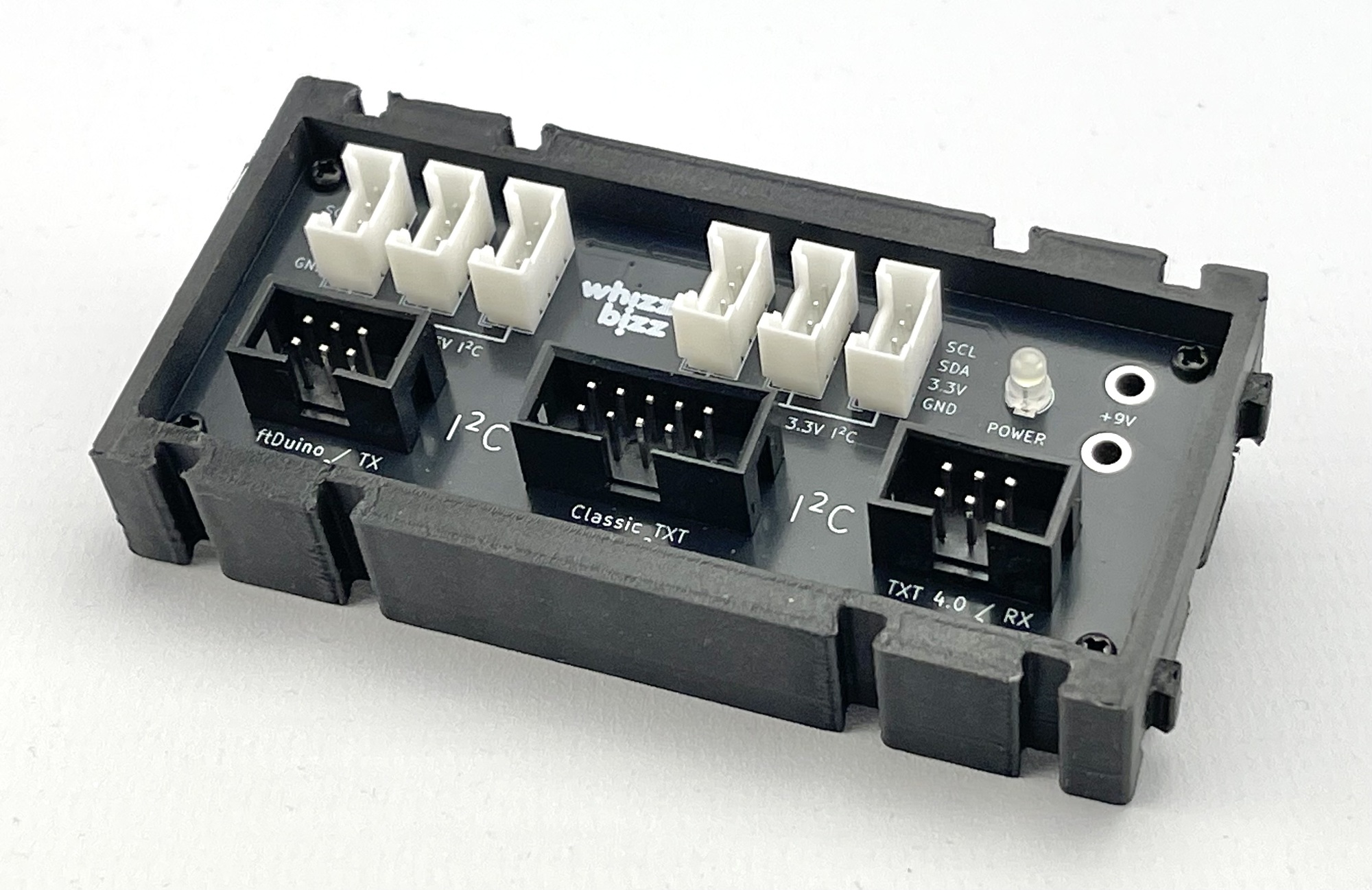
This led to the I2C Hub shown in Figure 8. The schematic, PCB design, and 3D files for printing the enclosure can be found on my GitHub.
All SMD components are hidden on the underside of the circuit board. For me, designing and building the hub served as a practice project in soldering circuit boards with SMD components. I used a solder paste stencil I printed myself to apply the solder paste.
Previously, I had manually applied solder paste to all the copper pads using a syringe, but this time I took a slightly different approach. I printed a small frame for the PCB and exported the solder paste Gerber file as an SVG file from KiCad. After importing this into Affinity Designer, I made the smallest paste pads (for the BSS138 MOSFETs) slightly larger and exported this pad pattern, including the surrounding PCB edge cut for reference, to Blender.
In Blender, I created a mesh and extruded it to give it some thickness. This became the Boolean object used to cut the correct holes in the deskel flap. I was pleased with the result, and it was fairly easy to apply solder paste to all the pads.
In addition, I experimented for the first time with a hot plate for the actual soldering process. The results were very encouraging. I made the short video above based on my findings.
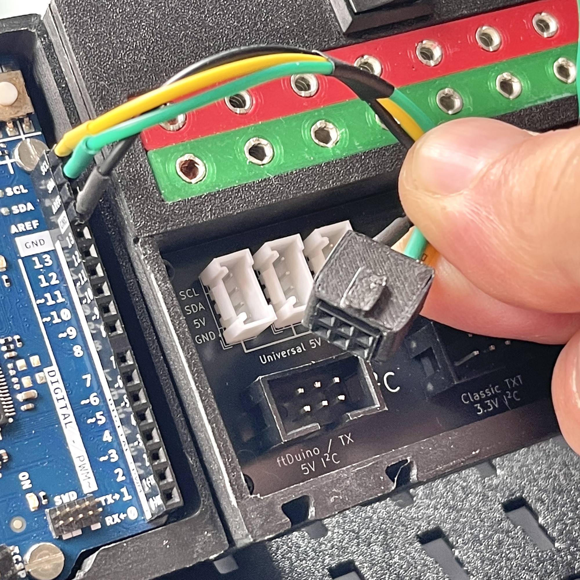
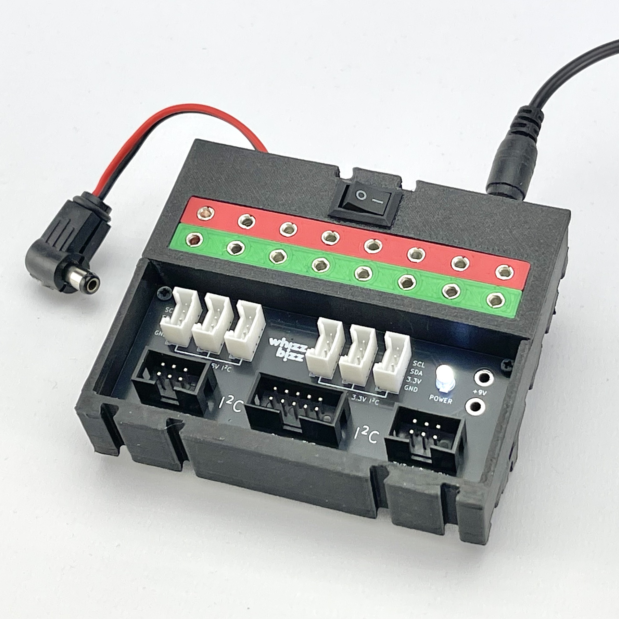
When using a Fischertechnik controller, a single 9-volt connection is sufficient to supply all Grove connectors with the correct voltages. I also created a version of the enclosure that can be powered directly by a DC adapter, as shown in the photo on the right. This version has a convenient on/off switch, passes the power supply voltage through to the Arduino board being used, and also makes it available for connecting cables with the familiar 2.5 mm Fischertechnik plugs.
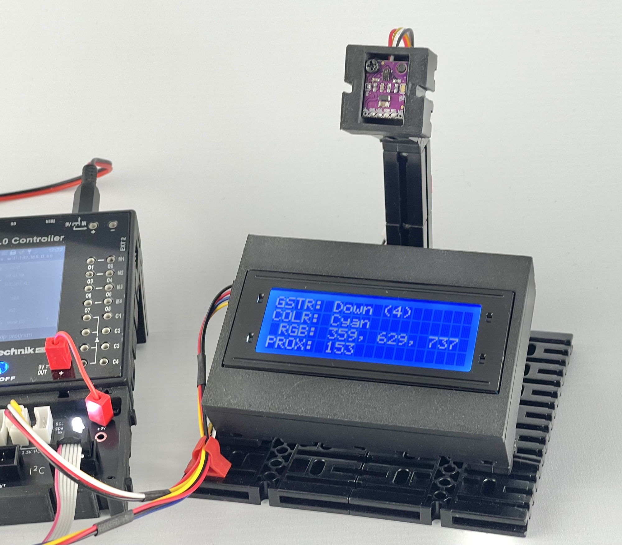
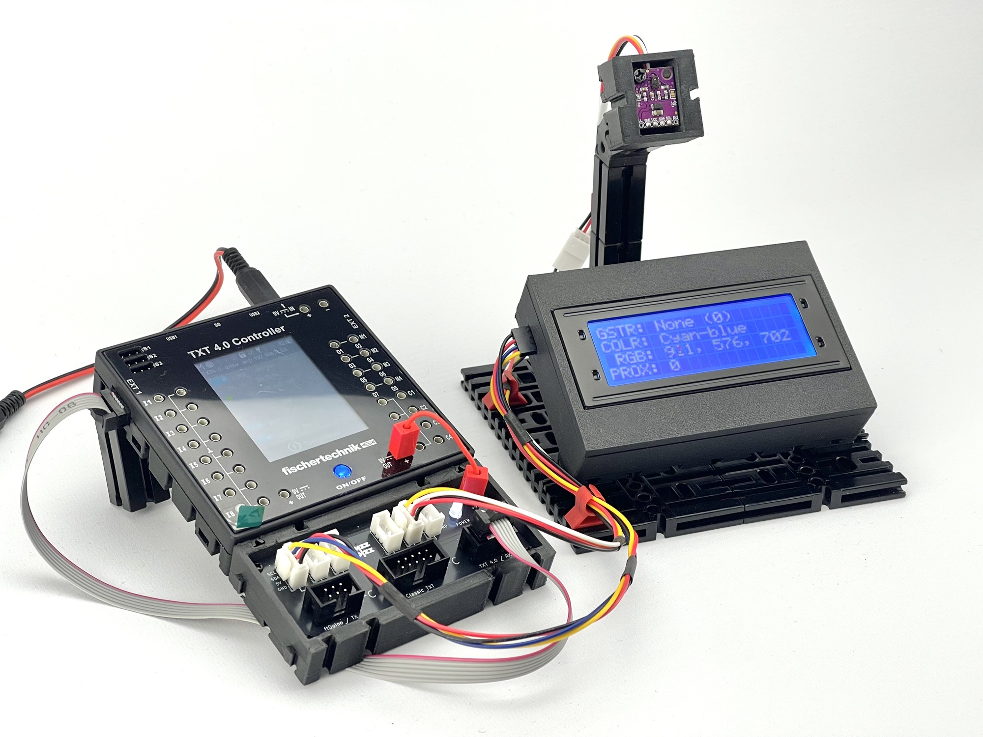
As a test project for the I2C Hub with the TXT4.0 Controller, I decided to display the data read via I2C from a 3.3-volt motion sensor on a 5-volt LCD display controlled via the same I2C bus.
Both the 10-pin and 6-pin versions of the fischertechnik Gesture Sensor (No. 183267) from the Robotics Add-On: Competition use the Avago/Broadcom APDS-9960 sensor. This is a digital chip that combines the following functions:
The I2C address of the APDS-9960 sensor—both for the standalone, commercially available sensor board (GY-9960) I used and for the 10-pin and 6-pin versions of the fischertechnik “Gesture Sensor”—is 0x39 by default. Therefore, reading data from this sensor poses no problem whatsoever.
It took a lot more effort to get the 2004A LCD display working on the TXT4.0 Controller! In the excellent I2cCode TXT4.0 library by “caliope,” I only found support for the SparkFun Qwiic 20x4 SerLCD. That display contains its own microprocessor (ATmega328P). The 2004A display, however, has a much simpler HD44780 controller and uses the common PCF8574 I/O expander for I2C communication.
Eventually, I managed to write a simple LCD driver for this controller in ROBO Pro Coding so that the display could ultimately be used for the experiment to display the measurement values from the motion sensor. Interested fischertechnik colleagues can find this LCD library under the name ‘LCD_2004A_over_I2C’ in the fischertechnik Cloud GitLab.
Although writing to the display is relatively slow, this “proof-of-concept” works perfectly. I have uploaded this program to the fischertechnik Cloud GitLab under the name “Gesture-LCD-2004A.”
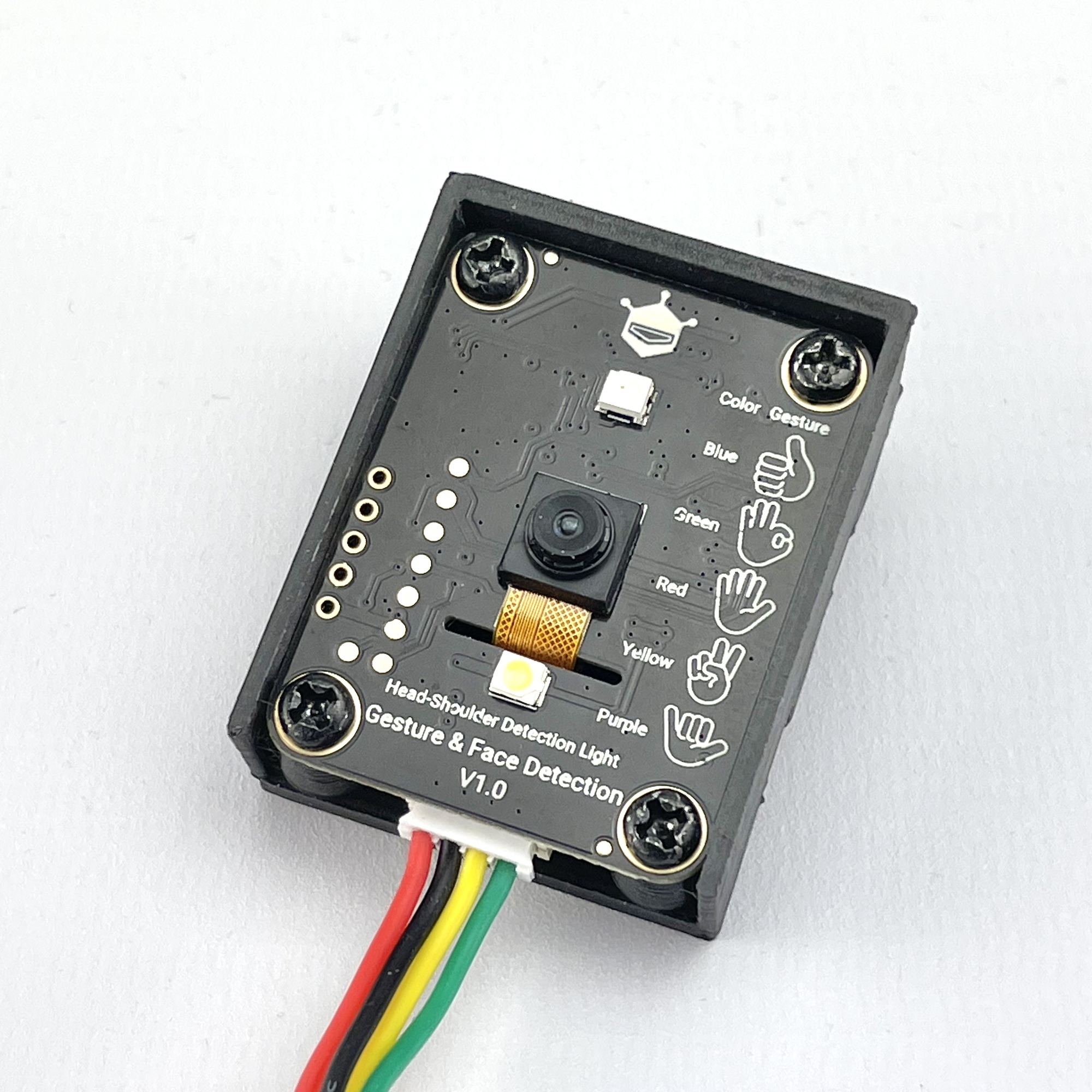
The APDS-9960 sensor in the fischertechnik Gesture Sensor is already a fairly classic motion sensor; nowadays, there are smart sensors with a camera and AI that can also recognize hand gestures without movement, as well as faces, etc. A popular option is the DFRobot SEN0626 Gravity AI Gesture & Face Detection Sensor.
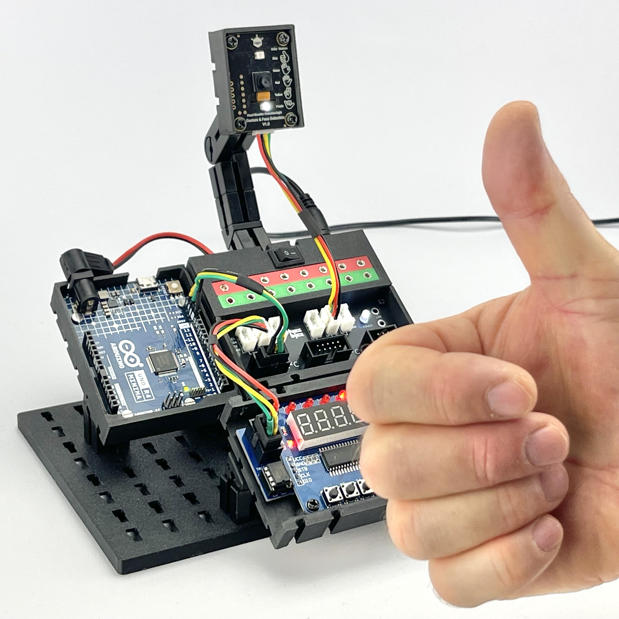
For the (5-volt) display on the I2C bus, I chose a so-called “LED & Key” board with a TM1638 controller. This is an experimental board with eight push buttons, eight LEDs, and eight 7-segment displays. I had just recently built the I2C control circuit for this board.
Although the power connectors for the Fischertechnik plugs weren’t necessary, I decided to use the version of the hub that allows for easy connection of a DC adapter. To connect the gesture sensor to the 3.3-volt I2C bus, I used a Qwiic-to-Grove adapter cable. I connected the display board to the 5-volt I2C bus. Both devices draw their power from the hub and do not place a load on the microcontroller board for this purpose.
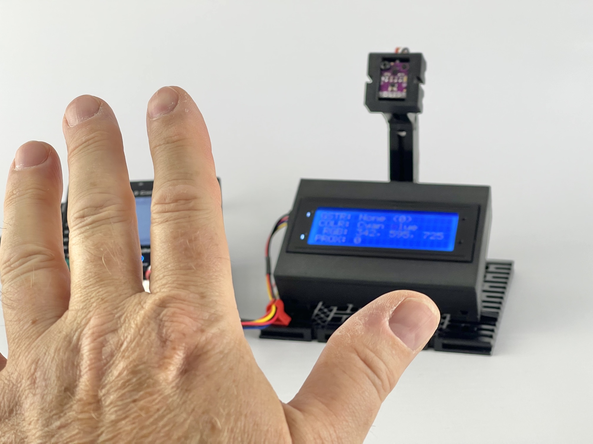
The images below show the result. The LEDs on the board indicate the position from the center where the sensor detected a “shoulder with head.” The corresponding 7-segment display shows the gesture number, if recognized.